AEM Performance Electronics 2001-2005 Honda K Series User manual
P/N 30-3502
2001–2005 Honda K Series
Infinity 506 and Infinity 508*
Plug & Play Adapter Harness
Instruction
Manual
WARNING!
Improper installation and/or adjustment of this product can result in major engine/vehicle damage. For
technical assistance visit our dealer locator to find a professional installer/tuner near you.
Note: AEM holds no responsibility for any engine damage or personal injury that results from the
misuse of this product, including but not limited to injury or death.
*See next page for important information regarding the use of this harness with Infinity 508
AEM Performance Electronics
AEM Performance Electronics, 2205 126th Street Unit A, Hawthorne, CA90250
Phone: (310) 484-2322 Fax: (310) 484-0152
http://www.aemelectronics.com
Instruction Part Number: 10-3502
Document Build 1/21/2021
STOP!
THIS PRODUCT HAS LEGAL RESTRICTIONS.
READ THIS BEFORE INSTALLING/USING!
WARNING! THIS IS A RACE ONLY PRODUCTMANUFACTURED AND SOLD FOR INSTALLATION ON VEHICLES DESIGNED TO BE USED
SOLELY FOR COMPETITION PURPOSES. ONCE THIS PART IS INSTALLED, THE VEHICLE MAY NEVER BE USED, OR REGISTERED
OR LICENSED FOR USE, ON A PUBLIC ROAD OR HIGHWAY. IF YOU INSTALL THIS PART ON YOUR VEHICLE AND USE THE VEHICLE
ON A PUBLIC ROAD OR HIGHWAY, YOU WILL VIOLATE THE CLEAN AIR ACT AND MAY BE SUBJECTTO PERSONAL CIVIL OR
CRIMINAL LIABILITY, INCLUDING FINES OF UP TO $4,819 PER DAY.
IT IS THE RESPONSIBILITY OF THE INSTALLER AND/OR USER OF THIS PRODUCTTO ENSURE THAT IT IS USED IN COMPLIANCE
WITH ALL APPLICABLE LAWS AND REGULATIONS. IF THIS PRODUCT WAS PURCHASED IN ERROR, DO NOTINSTALL AND/OR USE
IT. THE PURCHASER MUST ARRANGE TO RETURN THE PRODUCT FOR A FULL REFUND.
THIS POLICY ONLY APPLIES TO INSTALLERS AND/OR USERS WHO ARE LOCATED IN THE UNITED STATES; HOWEVER
CUSTOMERS WHO RESIDE IN OTHER COUNTRIES SHOULD ACT IN ACCORDANCE WITH THEIR LOCAL LAWS AND REGULATIONS.

2
© 2021 AEM Performance Electronics
P/N 30-3502
OVERVIEW
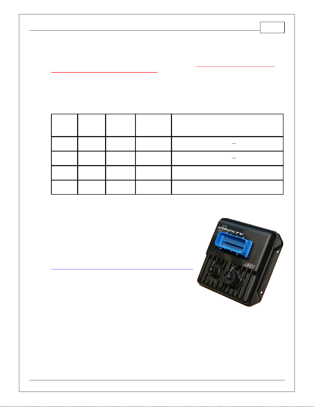
The 30-3502 AEM Infinity Adapter Kit was designed for the 2001–2005 Honda K Series. This is a true
standalone systemthat eliminates the use of the factory ECU. The use of this adapter makes the kit
“plug and play” so no cutting or splicing wires is necessary. The base configuration files available for
the Infinity EMS are starting points only and will need to be modified for every specific application.
*The AEMInfinity EMS will not support the factory A/C Switch and Coolant Gauge that are driven by
Honda's MultiplexSystem.
The available AEM Infinity EMS part numbers for this adapter kit are:
·
30-7106 Infinity 506
·
30-7108 Infinity 508
GETTING STARTED
Refer to the 10-7100 for EMS 30-7100 Infinity Quick Start Guide for additional information on getting
the engine started with the Infinity EMS. The base session is located in C:\Documents\AEM\Infinity
Tuner\Sessions\Base Sessions
DOWNLOADABLE FILES
Files can be downloaded from www.aeminfinity.com. An experienced tuner must be available to
configure and manipulate the data before driving can commence. The Quick Start Guide and Full
Manual describe the steps for logging in and registering at www.aeminfinity.com. ThThese documents
are available for download in the Support section of the AEM Electronics website:
http://www.aemelectronics.com/products/support/instructions
Downloadable Configuration files for 2001–2005 Honda K Series
·
v96.X Inf-506 Universal
·
v96.X Inf-508 Universal
OPTIONS
30-2001 UEGO Wideband O2 Sensor
Bosch LSU4.2 Wideband O2 Sensor that connects to AEM 30-3600 UEGO Wideband O2 Sensor
Extension Harness
30-3600 UEGO Wideband O2 Sensor Extension Harness
Extension harness to connect AEM UEGO Wideband O2 sensor to 6-pin Deutsch
30-3602 IP67 Logging Cable
USB A-to-A extension cable: 39” long with right angled connector and bayonet style lock
2001–2005 Honda K Series 3
© 2021 AEM Performance Electronics
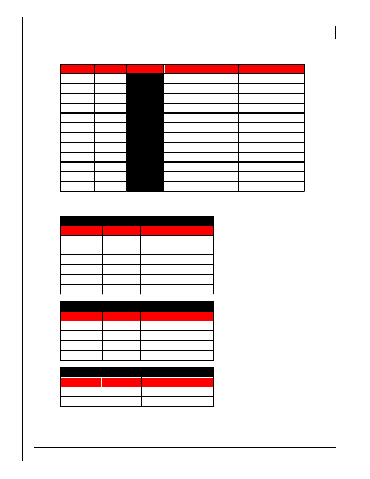
*IMPORTANT INFINITY 508 INFORMATION
The primary difference between the 30-7106 Infinity 506 and 30-7108 Infinity 508 is that the 508 lacks
Peak & Hold injector drivers to run low impedance fuel injectors. High impedance (saturated, high-z)
fuel injectors must be used with the Infinity 508.
The Infinity 506 and Infinity 508 share a common pinout with the exception of four pins where the
Infinity 508 has two each additional fuel injector and ignition coil drivers. Due to the additional fuel
injector and ignition coil drivers, the 8h has two fewer digital inputs and lowside outputs. Use of this
harness with an Infinity-8h will require slight modification and could result in loss of some plug and play
function.
Infinity
Pin
Infinity
506
Function
Infinity
508
Function
30-3502 PnP
Honda Pin
Notes
C1-3
Lowside6
Injector7
C5
Available LS6 on Infinity506 or Injector7 on Infinity
508
C1-4
Lowside7
Injector8
C4
Available LS7 on Infinity506 or Injector8 on Infinity
508
C1-31
Digital6
Coil7
Unpopulated
Available Digital6 on Infinity506; Coil7 not used on
Infinity508.
C1-32
Digital7
Coil8
Unpopulated
Available Digital7 on Infinity506; Coil8 not used on
Infinity508.
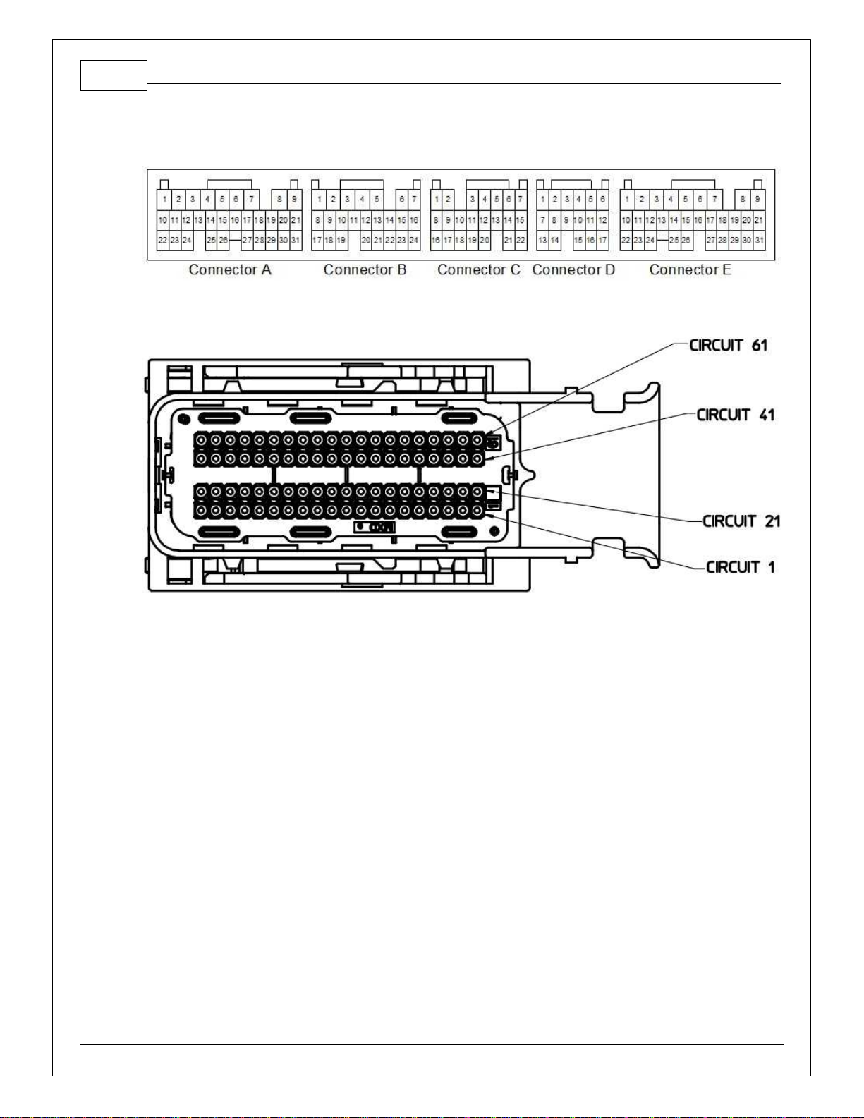
INFINITY CONNECTORS
The AEM Infinity EMS uses the MX123 Sealed Connection
System from Molex. AEM strongly recommends that users
become familiar with the proper tools and procedures for
working with these high density connectors before attempting
any modifications. The entire MolexMX123 User Manual can
be downloaded direct from Molexat:
http://www.molex.com/mx_upload/family//MX123UserManual.pdf

4
© 2021 AEM Performance Electronics
P/N 30-3502
INFINITY ADAPTER HARNESS
Included with the 2001–2005 Honda K Series kit is an adapter harness. This is used to make the
connection between the AEM Infinity EMS and the Honda wiring harness plug and play. This is depicted
belowwith the 80-pin connector and the Honda header. There are also a fewother integrated
connectors within this harness described below.
The gray Deutsch 6P DTM “LAMBDA” connector is for connecting a UEGO wideband Bosch LSU4.2
sensor (AEM 30-2001). The UEGO extension harness (AEM 30-3600) mates the adapter harness to the
sensor.
The gray Deutsch 4P DTM connector is used for “AEMNET”. AEMNet is an open architecture based on
CAN 2.0 which provides the ability for multiple enabled devices, such as dashboards, data loggers, etc.,
to easily communicate with one another through two twisted cables (CAN+/CAN-).
The black Delphi 2-pin “FLASH” connector is used for secondary hardware flashing. The included shunt
connector jumps the 2 wires together. Once initially flashed, the EMS is normally upgraded in the
software, not using this connector.
The red flying lead labeled “Battery+” is to be connected to a permanent +12V source. This source
should be independent of the ignition switch. The OEM Honda ECU does not have a permanent +12V
power pin, so this must be sourced separate from the OEM connector and should be protected with a
5A fuse.
2001–2005 Honda K Series 5
© 2021 AEM Performance Electronics
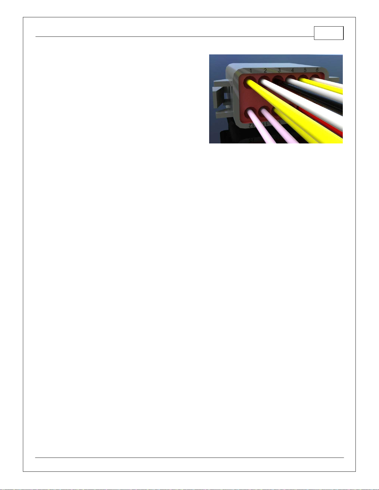
The gray Deutsch 12P DTM “AUX” connector (shown
below) is used to adapt many common ancillary
inputs and outputs easily. Included in the kit are a
DTM 12P mating connector, 12 DTM terminals, and a
DTM 12P wedgelock. If used, these components will
need to be terminated by the installer or end user
with 16–22awg wire (not included). Note: The pin
numbering is molded into the connector, as shown.
6
© 2021 AEM Performance Electronics
P/N 30-3502
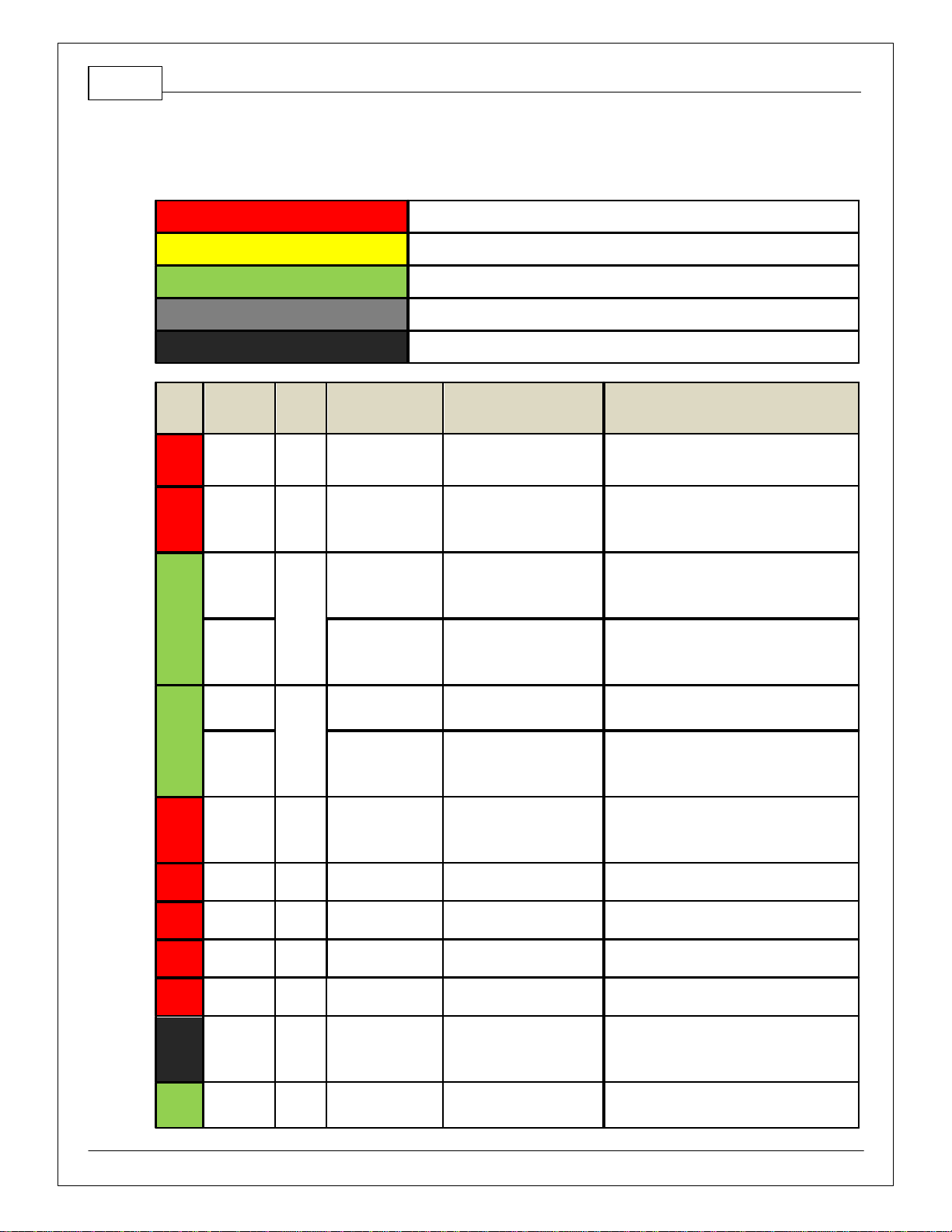
PINOUTS
InfinityPinout
Dedicated
Dedicated and not reconfigurable
Assigned
Assigned but reconfigurable
Available
Available for user setup
Not Applicable
Not used in this configuration
Required
Required for proper function
Infinity
Pin
Infinity
Assignmen
t
Honda
Pin
Honda Description
Infinity Hardware
Specification
Notes
1
LS 4
E26
Engine Speed Pulse
Lowside switch, 4Amax, No
internal flyback diode.
The tachometer is pre-calibrated using a
combination of the LS4_Freq [Hz]1-axis table
and the LS4_Duty[%] 2-axis table.
2
LS 5
B23
Variable Valve
Timing Control
Lowside switch, 4Amax with
internal flyback diode.
Inductive load should NOT
have full time power.
The Variable Valve Timing Control is pre-
calibrated using a combination of the LS5_Freq
[Hz] 1-axis table and the LS5_Duty[%] 2-axis
table.
3
LS 6
(Infinity6)
C5
---
Lowside switch, 4Amax with
internal flyback diode.
Inductive load should NOT
have full time power.
See Wizard page "LowSide Assignment Tables"
for output assignment. (Infinity6 only)
Injector 7
(Infinity8h)
---
For use with high impedance
(10-15
ohms) injectors only,
1.7Amax.
Spare injector output Injector 7 (Infinity8h only)
4
LS 7
(Infinity6)
C4
---
Lowside switch, 4Amax, No
internal flyback diode.
See Wizard page "LowSide Assignment Tables"
for output assignment. (Infinity6 only)
Injector 8
(Infinity8h)
---
For use with high impedance
(10-15
ohms) injectors only,
1.7Amax.
Spare injector output Injector 8 (Infinity8h only)
5
UEGO1
Heat
---
---
Bosch UEGO controller
Lowside switch for UEGO heater control.
Connect to pin 4 of Bosch UEGO sensor. NOTE
that pin 3 of the Sensor is heater (+) and must
be power bya fused/switched 12Vsupply.
6
UEGO1 IA
---
---
Bosch UEGO controller
Trim Current signal. Connect to pin 2 of Bosch
UEGO sensor.
7
UEGO1 IP
---
---
Bosch UEGO controller
Pumping Current signal. Connect to pin 6 of
Bosch UEGO sensor.
8
UEGO1 UN
---
---
Bosch UEGO controller
Nernst Voltage signal. Connect to pin 1 of
Bosch UEGO sensor.
9
UEGO1 VM
---
---
Bosch UEGO controller
Virtual Ground signal. Connect to pin 5 of Bosch
UEGO sensor.
10
+12VPerm
Power
---
Voltage Back Up
Dedicated power
management CPU
Full time batterypower. MUST be powered
before the ignition switch input is triggered.
NOTE:Fused batterypower need to supplyto
the flying lead on the AEMadapter harness.
11
Coil 4
A27
Ignition Coil Pulse
No. 4
25 mAmaxsource current
0–5Vfalling edge fire. Do NOT connect directly
to coil primary. Must use an ignitor or CDI that

2001–2005 Honda K Series 7
© 2021 AEM Performance Electronics
Infinity
Pin
Infinity
Assignmen
t
Honda
Pin
Honda Description
Infinity Hardware
Specification
Notes
accepts a falling edge fire signal.
12
Coil 3
A28
Ignition Coil Pulse
No. 3
25 mAmaxsource current
0–5Vfalling edge fire. Do NOT connect directly
to coil primary. Must use an ignitor or CDI that
accepts a falling edge fire signal.
13
Coil 2
A29
Ignition Coil Pulse
No. 2
25 mAmaxsource current
0–5Vfalling edge fire. Do NOT connect directly
to coil primary. Must use an ignitor or CDI that
accepts a falling edge fire signal.
14
Coil 1
A30
Ignition Coil Pulse
No. 1
25 mAmaxsource current
0–5Vfalling edge fire. Do NOT connect directly
to coil primary. Must use an ignitor or CDI that
accepts a falling edge fire signal.
15
---
---
---
---
---
16
---
---
---
---
---
17
VR0 (+) -
Crank
---
Differential Variable
Reluctance Zero Cross
Detection
See Setup Wizard page Cam/Crank for options.
18
VR0 (-) -
Crank
---
Differential Variable
Reluctance Zero Cross
Detection
See Setup Wizard page Cam/Crank for options.
19
VR1 (-) -
Cam
---
Differential Variable
Reluctance Zero Cross
Detection
See Setup Wizard page Cam/Crank for options.
20
VR1 (+) -
Cam
---
Differential Variable
Reluctance Zero Cross
Detection
See Setup Wizard page Cam/Crank for options.
21
LS 2
B6
Radiator Fan Control
Lowside switch, 4Amax, No
internal flyback diode.
See Setup Wizard Page "LowSide Assignment
Tables" for output assignment and 2D table
"LS2_Duty[%]" for on/off activation.
22
LS 3
A12
Idle Air Control Valve
Lowside switch, 4Amax with
internal flyback diode.
Inductive load should NOT
have full time power.
See Setup Wizard page and corresponding
Tables for Idle Air Control.
23
Sensor
GND
A10
Sensor Ground 1
Dedicated analog ground
Analog 0–5Vsensor ground also found on aux
connector.
24
Sensor
GND
A11
Sensor Ground 2
Dedicated analog ground
Analog 0–5Vsensor ground.
25
Digital 0 -
Crank
A7
CKP
10K pullup to 12V. Will work
with ground or floating
switches.
See Setup Wizard page Cam/Crank for options.
26
Digital 1 -
Cam1
A26
CMP2
10K pullup to 12V. Will work
with ground or floating
switches.
See Setup Wizard page Cam/Crank for options.
27
Digital 2 -
Cam2
A25
CMP1
10K pullup to 12V. Will work
with ground or floating
switches.
See Setup Wizard page Cam/Crank for options.
28
Digital 3 –
FlexFuel
---
---
10K pullup to 12V. Will work
with ground or floating
switches.
Found on the AuxConnector. Input can be
assigned to different pins. See Setup Wizard
page Input Function Assignments for input
mapping options.
29
Digital 4 -
VSS#1
A18
Vehicle Speed
Sensor
10K pullup to 12V. Will work
with ground or floating
switches.
See Setup Wizard page Vehicle Speed for
calibration constant.

8
© 2021 AEM Performance Electronics
P/N 30-3502
Infinity
Pin
Infinity
Assignmen
t
Honda
Pin
Honda Description
Infinity Hardware
Specification
Notes
30
Digital 5 -
---
---
10K pullup to 12V. Will work
with ground or floating
switches.
Found on the AuxConnector. Input can be
assigned to different pins. See Setup Wizard
page Input Function Assignments for input
mapping options.
31
Digital 6
(Infinity6)
---
10K pullup to 12V. Will work
with ground or floating
switches.
Input can be assigned to different pins. See
Setup Wizard page Input Function Assignments
for input mapping options.
*Coil 7 for Infinity8h
32
Digital 7
(Infinity6)
---
---
10K pullup to 12V. Will work
with ground or floating
switches.
Input can be assigned to different pins. See
Setup Wizard page Input Function Assignments
for input mapping options.
*Coil 8 for Infinity8h
33
GND
A4
Power Ground 1
Power Ground
Connects to chassis ground and AEMNet
34
CAN A-
---
---
Dedicated High Speed CAN
Transceiver
4P DTMConnector found in AEMadapter
harness. Contact AEMfor additional information.
35
CAN A+
---
---
Dedicated High Speed CAN
Transceiver
4P DTMConnector found in AEMadapter
harness. Contact AEMfor additional information.
36
CAN B -
---
---
Dedicated High Speed CAN
Transceiver
Not used
37
CAN B +
---
---
Dedicated High Speed CAN
Transceiver
Not used
38
Temp 1 -
Coolant
Temp
B8
Engine Coolant
Temp Sensor
12 bit A/D, 2.49K pullup to 5V
See "Coolant Temperature" Setup Wizard for
selection.
39
Temp 2 - Air
Temp
(Manifold)
B17
Intake Air Temp
Sensor
12 bit A/D, 2.49K pullup to 5V
See "Air Temperature" Setup Wizard for
selection.
40
Temp 3 -
Oil Temp
---
---
12 bit A/D, 2.49K pullup to 5V
Found on the AuxConnector. 0–5Vanalog
signal.
41
LS 0
E1
Fuel Pump Relay
Lowside switch, 4Amax, No
internal flyback diode.
Switched ground. Will prime for 2 seconds at
keyon and activate if RPM> 0.
42
LS 1
---
---
Lowside switch, 4Amax with
internal flyback diode.
Inductive load should NOT
have full time power.
Found in AuxConnector. See Setup Wizard
page Boost Control for options. Monitor
BoostControl [%] channel for output state.
43
GND
A5
Power Ground 2
Power Ground
Connect directlyto batteryground.
44
Knock 0
A9
Knock Sensor
Dedicated knock signal
processor
See Knock in Setup Wizard for options.
45
Knock 1
Dedicated knock signal
processor
See Knock in Setup Wizard for options.
46
GND
Power Ground
Connect directlyto batteryground.
47
12V_Relay_
Control
E7
Main RelayControl
0.7Amaxground sink for
external relaycontrol
Will activate at keyON and at keyOFF according
to the configuration settings.
48
+12VSW
(Ign Switch)
E9
Power Source 1
10K pulldown
Full time batterypower must be available at
infinitypin 10 before this input is triggered.
49
+5V_Out
A20
Sensor Voltage 1
Regulated, fused +5Vsupply
for sensor power
Analog sensor power and found on auxiliary
connector
50
+5V_Out
A21
Sensor Voltage 2
Regulated, fused +5Vsupply
for sensor power
Analog sensor power

2001–2005 Honda K Series 9
© 2021 AEM Performance Electronics
Infinity
Pin
Infinity
Assignmen
t
Honda
Pin
Honda Description
Infinity Hardware
Specification
Notes
51
Ana7 -
Throttle
A15
Throttle Position
Sensor
12 bit A/D, 100K pullup to 5V
0–5Vanalog signal. Do not connect signals
referenced to +12Vas this can permanently
damage the ECU. See the Setup Wizard Set
Throttle Range page for automatic min/max
calibration.
52
Ana8 - Map
A19
MAP Sensor
12 bit A/D, 100K pullup to 5V
0–5Vanalog signal. See the Manifold Pressure
in Setup Wizard for setup and calibration.
53
Ana9 - Fuel
Press
---
---
12 bit A/D, 100K pullup to 5V
0–5Vanalog signal found on the Auxiliary
Connector
54
VR2 (+) -
Driven
Wheel
---
---
Differential Variable
Reluctance Zero Cross
Detection
See Driven Wheel Speed Calibration in the
Setup Wizard Vehicle Speed page.
55
VR2 (-) -
Driven
Wheel
---
---
Differential Variable
Reluctance Zero Cross
Detection
See Driven Wheel Speed Calibration in the
Setup Wizard Vehicle Speed page.
56
VR3 (-) -
Tag Wheel
---
---
Differential Variable
Reluctance Zero Cross
Detection
See Non Driven Wheel Speed Calibration in the
Setup Wizard Vehicle Speed page.
57
VR3 (+) -
Tag Wheel
---
---
Differential Variable
Reluctance Zero Cross
Detection
See Non Driven Wheel Speed Calibration in the
Setup Wizard Vehicle Speed page.
58
HS Out 0
B15
VTEC solenoid Valve
0.7Amax, High Side Solid
State Relay
+12VHigh Side Drive. See Setup Wizard Honda
VTEC page for options.
59
Stepper_1B
---
---
Automotive, Programmable
Stepper Driver, up to 28Vand
±1.4A
Be sure that each internal coil of the stepper
motor is properlypaired with the 1A/1B and
2A/2B ECU outputs. Supports Bi-Polar stepper
motors only.
60
Stepper_2B
---
---
Automotive, Programmable
Stepper Driver, up to 28Vand
±1.4A
Be sure that each internal coil of the stepper
motor is properlypaired with the 1A/1B and
2A/2B ECU outputs. Supports Bi-Polar stepper
motors only.
61
HBridge0_0
---
---
5.0AmaxThrottle Control
Hbridge Drive
62
HBridge0_1
---
---
5.0AmaxThrottle Control
Hbridge Drive
63
+12V
A2/B1
Main Power
Main Power
12 volt power from relaypowers the Infinity,
Lambda sensor, and AEMNet
64
Injector 6
C3
---
Saturated or peak and hold,
3Amaxcontinuous
Spare injector output Injector 6
*No peak and hold injector for Infinity8h
65
Injector 5
C2
---
Saturated or peak and hold,
3Amaxcontinuous
Spare injector output Injector 5
*No peak and hold injector for Infinity8h
66
Injector 4
B2
Injector 4
Saturated or peak and hold,
3Amaxcontinuous
Injector 4
*No peak and hold injector for Infinity8h
67
GND
---
---
Power Ground
Connects directlyto ground
68
+12V
A3
Main Power
Main Power
12 volt power from relaypowers the Infinity
69
Ana19 -
APP2
---
---
12 bit A/D, 100K pullup to 5V
0–5Vanalog signal. Do not connect signals
referenced to +12Vas this can permanently
damage the ECU.
70
Ana18 -
APP1
---
---
12 bit A/D, 100K pullup to 5V
0–5Vanalog signal. Do not connect signals
referenced to +12Vas this can permanently
damage the ECU.

10
© 2021 AEM Performance Electronics
P/N 30-3502
Infinity
Pin
Infinity
Assignmen
t
Honda
Pin
Honda Description
Infinity Hardware
Specification
Notes
71
Ana16
- Mode SW
---
---
12 bit A/D, 100K pullup to 5V
0–5Vanalog signal. Use +5V Out pins as power
supplyand Sensor Ground pins as the low
reference. Do not connect signals referenced to
+12Vas this can permanentlydamage the
ECU.
See the 1D lookup table 'Mode Switch' for input
state.
Also assignable to multiple functions. See
Setup Wizard for details.
72
Harness_Fl
ash_Enabl
e
---
---
10K pulldown
Not usuallyneeded for automatic firmware
updates through InfinityTuner. If connection
errors occur during update, jump the 12VFlash
Connector before proceeding with upgrade.
Disconnect the 12VFlash Connector after the
update.
73
Ana13 - Oil
Press
---
---
12 bit A/D, 100K pullup to 5V
0–5Vanalog signal found on the Auxiliary
Connector
74
Ana11 -
Shift SW
---
---
12 bit A/D, 100K pullup to 5V
0–5Vanalog signal found on the Auxiliary
Connector
75
Ana10
---
---
12 bit A/D, 100K pullup to 5V
0–5Vanalog signal found on the Auxiliary
Connector
76
Injector 3
B3
Injector 3
Saturated or peak and hold,
3Amaxcontinuous
Injector 3
*No peak and hold injector for Infinity8h
77
Injector 2
B4
Injector 2
Saturated or peak and hold,
3Amaxcontinuous
Injector 2
*No peak and hold injector for Infinity8h
78
Injector 1
B5
Injector 1
Saturated or peak and hold,
3Amaxcontinuous
Injector 1
*No peak and hold injector for Infinity8h
79
Stepper_2A
---
---
Automotive, Programmable
Stepper Driver, up to 28Vand
±1.4A
Be sure that each internal coil of the stepper
motor is properlypaired with the 1A/1B and
2A/2B ECU outputs. Supports Bi-Polar stepper
motors only.
80
Stepper_1A
---
---
Automotive, Programmable
Stepper Driver, up to 28Vand
±1.4A
Be sure that each internal coil of the stepper
motor is properlypaired with the 1A/1B and
2A/2B ECU outputs. Supports Bi-Polar stepper
motors only.
2001–2005 Honda K Series 11
© 2021 AEM Performance Electronics
AUX Connector Pinout
Deutsch Pin
Infinity Pin
Wire Color
Pin Name
Default Pin Function
1
53
Black
Analog_In_9
Fuel Pressure
2
40
Black
Analog_In_Temp_3
Oil Temperature
3
23
Black
AGND
Sensor Ground
4
49
Black
+5V_OUT
Sensor +5V
5
73
Black
Analog_In_13
Oil Pressure
6
30
Black
Digital_In_5
Clutch Switch, Nitrous Arm
7
42
Black
LS1
Boost Control
8
63
Black
+12V
+12V
9
28
Black
Digital_In_3
Flex Fuel Sensor (Hz)
10
71
Black
Analog_In_16
Charge Pressure
11
75
Black
Analog_In_10
Baro Pressure
12
74
Black
Analog_In_11
Exh Back Pressure
Miscellaneous Pinouts
LAMBDA 1
Deutsch Pin
Infinity Pin
Default Pin Function
1
8
UEGO1 UN
2
6
UEGO1 IA
3
63
+12V
4
5
UEGO1 Heat
5
9
UEGO1 VM
6
7
UEGO1 IP
AEMNet
Deutsch Pin
Infinity Pin
Default Pin Function
1
35
CAN A+
2
34
CAN A-
3
63
+12V
4
33
Ground
FLASH ENABLE
Delphi Pin
Infinity Pin
Default Pin Function
A
10
Permanent Power
B
72
Harness Flash Enable
12
© 2021 AEM Performance Electronics
P/N 30-3502
Honda Pin Numbering
InfinityPin Numbering
Viewed From Wire Side

2001–2005 Honda K Series 13
© 2021 AEM Performance Electronics
This manual suits for next models
1
Table of contents
Other AEM Performance Electronics Automobile Accessories manuals


Popular Automobile Accessories manuals by other brands


Firstech
Firstech FTI-HDP6 Vehicle Coverage & Preparation Notes

Kolpin Powersports
Kolpin Powersports 26300 Mounting and operation instructions

Havis-Shields
Havis-Shields Telescoping Computer Base C-TCB-7-IMP Install instructions

Victory 4x4
Victory 4x4 UNI-UPRS Install instructions

Kuda-Phonebase
Kuda-Phonebase 287040 Installation instruction

Car Cover Division
Car Cover Division WeatherShield HD Instructions for the use and care


