AEM 30-3500 User manual
P/N 30-3500
1993–1998 Toyota Supra MKIV Twin Turbo
Manual Transmission
Plug & Play Adapter Harness
AEM Performance Electronics
AEM Performance Electronics, 2205 126th Street Unit A, Hawthorne, CA 90250
Phone:(310) 484-2322 Fax:(310) 484-0152
http://www.aemelectronics.com
Instruction Part Number:10-3500
Document Build 4/2/2015
Instruction
Manual
STOP!
THIS PRODUCT HAS LEGAL RESTRICTIONS.
READ THIS BEFORE INSTALLING/USING!
THIS PRODUCTMAY BEUSEDSOLELY ONVEHICLES USEDINSANCTIONEDCOMPETITIONWHICHMAY NEVERBEUSEDUPONA
PUBLIC ROAD ORHIGHWAY, UNLESS PERMITTEDBY SPECIFICREGULATORY EXEMPTION. (VISIT THE“EMISSIONS” PAGEATHTTP://
WWW.SEMASAN.COM/EMISSIONS FORSTATEBY STATEDETAILS.)
IT IS THERESPONSIBILITY OFTHEINSTALLERAND/ORUSEROF THIS PRODUCTTO ENSURETHAT IT IS USEDINCOMPLIANCEWITH
ALL APPLICABLELAWS ANDREGULATIONS. IFTHIS PRODUCTWAS PURCHASEDINERROR, DO NOTINSTALL AND/ORUSEIT. THE
PURCHASERMUST ARRANGETO RETURN THEPRODUCT FOR A FULL REFUND.
THIS POLICY ONLY APPLIES TO INSTALLERS AND/ORUSERS WHO ARELOCATEDINTHEUNITEDSTATES; HOWEVERCUSTOMERS
WHO RESIDEINOTHERCOUNTRIES SHOULDACTINACCORDANCEWITHTHEIRLOCAL LAWS ANDREGULATIONS.
WARNING: This installation is not for the tuning novice! Use this system with EXTREME caution! The AEM
Infinity Programmable EMS allows for total flexibility in engine tuning. Misuse or improper tuning of this
product can destroy your engine! If you are not well versed in engine dynamics and the tuning of engine
management systems DO NOT attempt the installation. Refer the installation to an AEM-trained tuning
shop or call 800-423-0046 for technical assistance.
NOTE: All supplied AEM calibrations, Wizards and other tuning information are offered as potential
starting points only. IT IS THE RESPONSIBILITY OF THE ENGINE TUNER TO ULTIMATELY CONFIRM IF THE
CALIBRATION IS SAFE FOR ITS INTENDED USE. AEM holds no responsibility for any engine damage that
results from the misuse or mistuning of this product!

2
© 2015 AEM Performance Electronics
P/N 30-3500
OVERVIEW
The 30-3500 AEM Infinity Adapter Kit is designed for the 1993–1998 Toyota Supra MKIV Twin Turbo
(manual transmission). This is a true standalone system that eliminates the use of the factory ECU. The
use of this adapter makes the kit “plug and play” so no cutting or splicing wires is necessary. The base
configuration files available for the Infinity EMS are starting points only and will need to be modified for
every specific application.
The available AEM Infinity EMS part numbers for this adapter kit are:
30-7100 INFINITY-8
30-7101 INFINITY-10
GETTING STARTED
Refer to the 10-7100 for EMS 30-7100 Infinity Quick Start Guide for additional information on getting
the engine started with the Infinity EMS. Toyota Supra MKIV Twin Turbo base sessions are located in C:
\Documents\AEM\Infinity Tuner\Sessions\Base Sessions
DOWNLOADABLE FILES
Files can be downloaded from www.aeminfinity.com. An experienced tuner must be available to configure
and manipulate the data before driving can commence. The Quick Start Guide and Full Manual describe
the steps for logging in and registering at www.aeminfinity.com. These documents are available for
download in the Support section of the AEM Electronics website: http://www.aemelectronics.com/
products/support/instructions
Downloadable files for 1993–1998 MKIV Toyota Supra Twin Turbo
7100-XXXX-62 Infinity-10 (XXXX= serial number)
7101-XXXX-63 Infinity-8 (XXXX= serial number)
OPTIONS
30-3600 UEGO Wideband O2 Sensor Extension Harness
Extension harness to connect AEM UEGO Wideband O2 sensor to 6-pin Deutsch
30-3601 IP67 Comms Cable
30-3602 IP67 Logging Cable
USB A-to-A extension cable: 39” long with right angled connector and bayonet style lock

1993–1998 Toyota Supra MKIV Twin Turbo 3
© 2015 AEM Performance Electronics
INFINITY CONNECTORS
The AEM Infinity EMS uses the MX123 Sealed Connection System
from Molex. AEM strongly recommends that users become familiar
with the proper tools and procedures for working with these high
density connectors before attempting any modifications. The entire
Molex MX123 User Manual can be downloaded direct from Molex at:
http://www.molex.com/mx_upload/family//MX123UserManual.pdf
INFINITY ADAPTER HARNESS
Included with the 1993–1998 Toyota Supra MKIV Twin Turbo kit is an adapter harness. This is used to
make the connection between the AEM Infinity EMS and the Toyota wiring harness plug and play. This
is depicted below with the 73-pin and 56-pin connectors and the Toyota header. There are also a few
other integrated connectors.

4
© 2015 AEM Performance Electronics
P/N 30-3500
ECU SETUP WIZARD
Important Application Specific Settings
Engine
In the Wizard Engine tab confirm the following:
Number of Cylinders = 6
Engine Cycle Type = 4 Stroke
Ignition Type = Sequential (Coil On Plug)
Firing Order = 1-5-3-6-2-4

1993–1998 Toyota Supra MKIV Twin Turbo 5
© 2015 AEM Performance Electronics
Cam/Crank
In the Wizard Cam/Crank tab confirm the following:
Toyota Supra (1993–1998 Turbo)
Open the Advanced Setup tab and set the following:
Crank Noise Cancellation = 70
Cam 1 Noise Cancellation = 70
Add the 1-Axis Lookup Table VR_PwmDuty [%] to your layout. Set the following:
Ignition Sync
Add a text grid control to your layout and select the following channels. Make sure their values match
the settings below for initial timing sync.
TrigOffset [degBTDC] = 23.00
CamSyncAdjustment = 11.00
See QuickStart Guide section Setup: Ignition Sync for instructions on timing sync.
Idle Stepper Max Steps
Go to Setup Wizard Idle page and confirm the following:
Idle Stepper Max Steps = 132
AC Input Switch
Go to Setup Wizard Input Function Assignment page and confirm the following:
AC Input Switch Setup = Analog17[V]

6
© 2015 AEM Performance Electronics
P/N 30-3500
IDLE AIR CONTROL VALVE REQUIREMENTS
Many Toyota, Mitsubishi, and other vehicles use an Idle Air Control Valve with a Unipolar Stepper Motor
(6-pin connector) and MUST be modified. See instructions below. A Bipolar Stepper Motor (e.g., GM)
will have a 4-pin connector and DOES NOT need to be modified.
*This info does not apply to vehicles that utilize IACV solenoids.
The 2 center pins (Black-Red wires) supply 12V power to the stepper motor in the factory setup,
however these pins MUST BE DISCONNECTED before powering the AEM Infinity ECU.

1993–1998 Toyota Supra MKIV Twin Turbo 7
© 2015 AEM Performance Electronics
Step 1: Disconnect connector from IACV housing and gently remove the retainer from the connector.
Step 2: Use a small flat-blade screwdriver/pick to move the terminal locks while pulling the Black-Red
wires out from the backside of the connector.

8
© 2015 AEM Performance Electronics
P/N 30-3500
Step 3: Use heat shrink to insulate both 12V wires, and then zip-tie the insulated wires to a nearby
loom.
Step 4: Reinstall the retainer, and then plug the connector back into the IACV.
1993–1998 Toyota Supra MKIV Twin Turbo 9
© 2015 AEM Performance Electronics
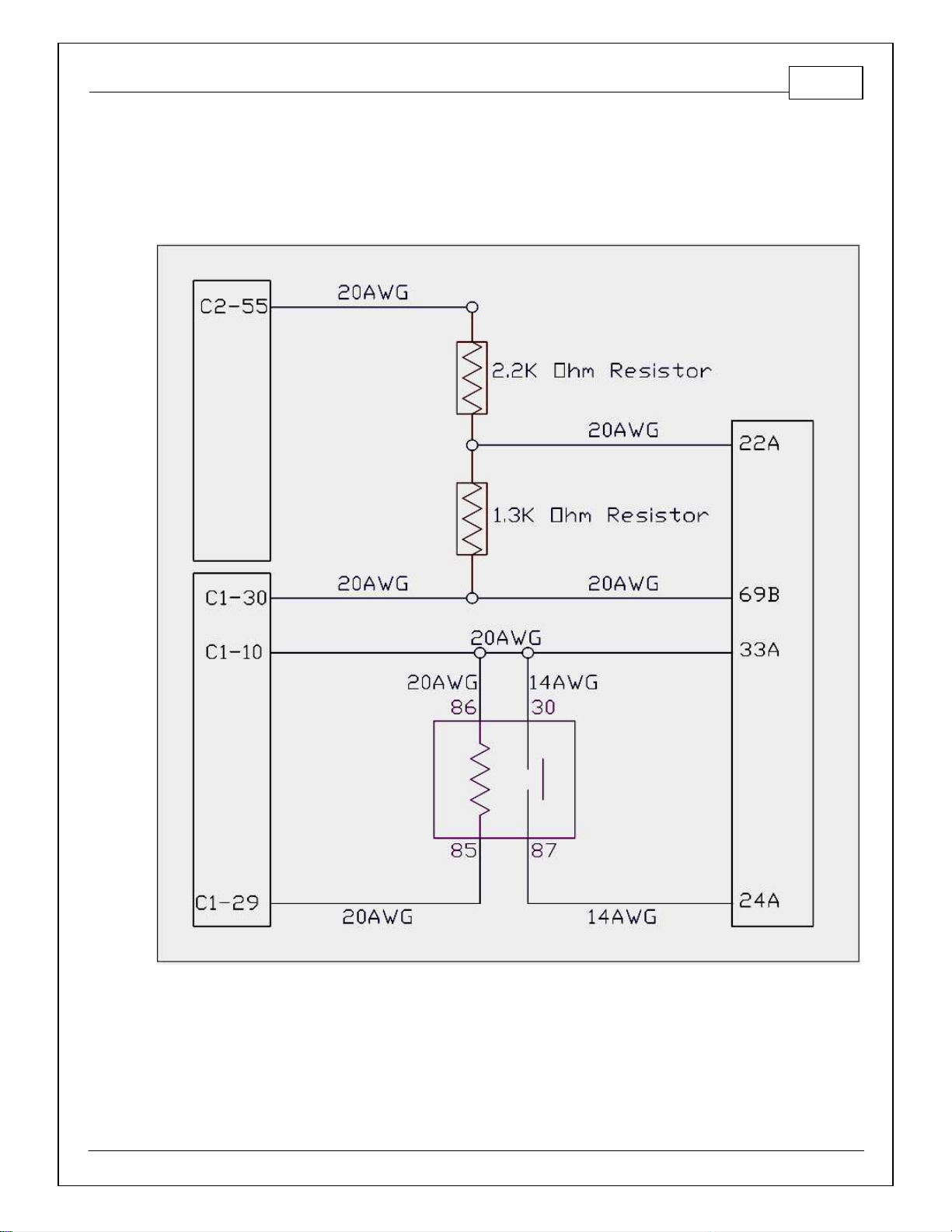
MAIN RELAY/FUEL PUMP SCHEMATIC
The 1993–1998 Toyota Supra Infinity patch harness requires a harness relay and fuel pump control to be
wired exactly as pictured below. Failure to do so may result in an unresponsive ECU and/or a no-start
condition.
10
© 2015 AEM Performance Electronics
P/N 30-3500
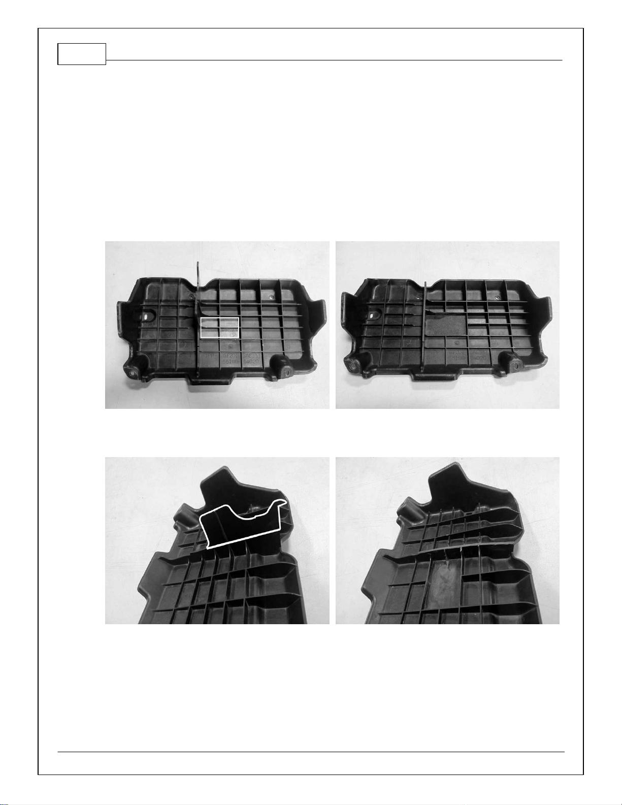
ECU COVER MODIFICATIONS
It is recommend that the OEM ECU cover panel be modified and reinstalled with the AEM Infinity EMS
when utilizing the mounting bracket. Failure to properly clearance and reinstall this panel (Toyota
PN#55199-14020) could potentially result in damage to the ECU, adapter harness, ECU connectors and/
or USB cables and connectors.
Please note clearance modifications below. These modifications should be performed with a die grinder,
90-degree sander, or plastic shears.
Step 1: Remove the four ribs located near the center of the cover as highlighted below.
Step 2: Trim the center support leg as outlined. Test fit, note, and trim any additional areas required.

1993–1998 Toyota Supra MKIV Twin Turbo 11
© 2015 AEM Performance Electronics
INFINITY EMS INSTALLATION
Step 1
Disconnect battery's negative cable.
Step 2
Locate factory Engine Control Unit
(ECU). Most ECU's are located in the
passenger kick panel, behind the center
console, or in the engine bay.

12
© 2015 AEM Performance Electronics
P/N 30-3500
Step 3
Unplug factory harness plugs at ECU
and remove factory ECU.

1993–1998 Toyota Supra MKIV Twin Turbo 13
© 2015 AEM Performance Electronics
Step 4
Plug factory harness plugs into AEM
Infinity Adapter Harness.
14
© 2015 AEM Performance Electronics
P/N 30-3500
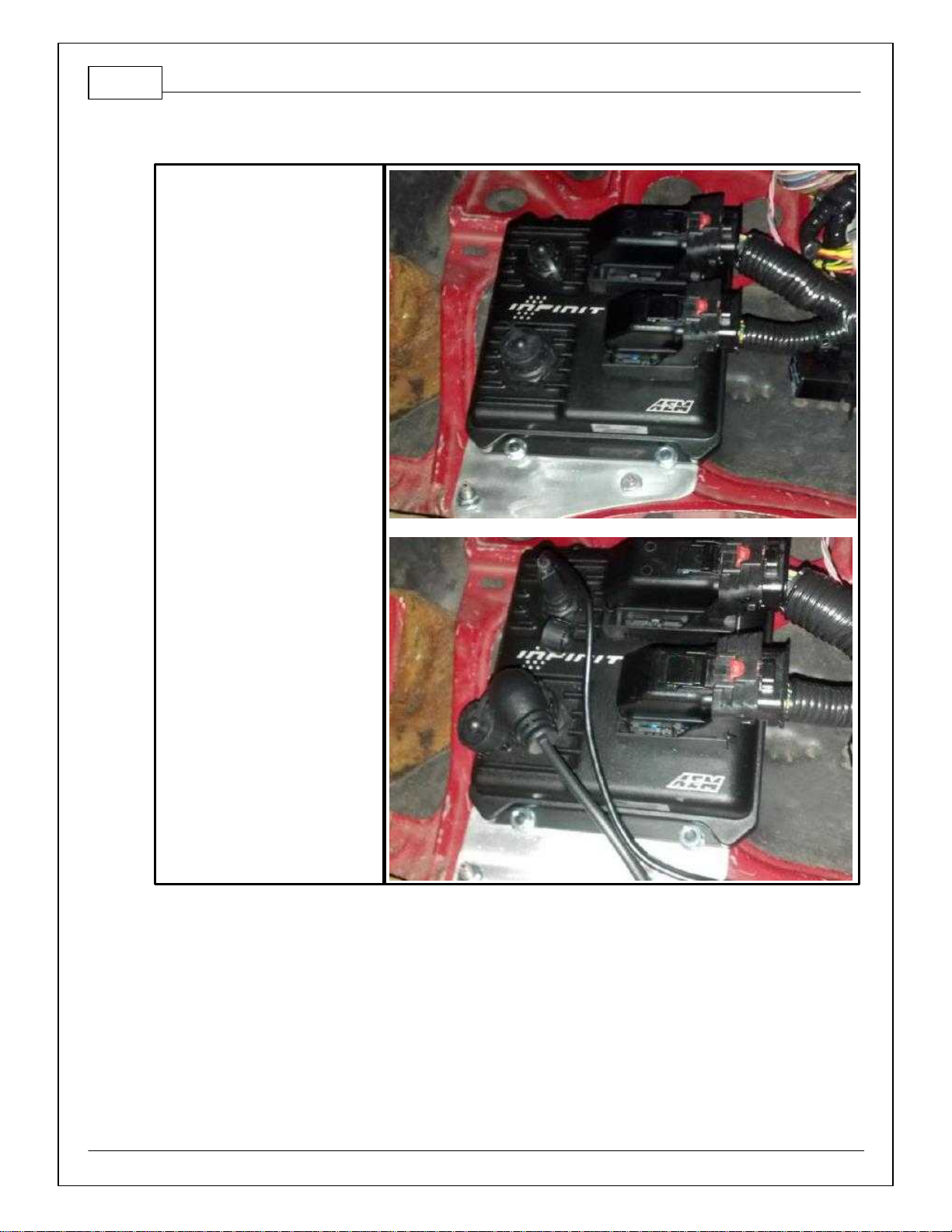
Step 5
Mount the Infinity ECU and
connect Infinity connectors and
USB cables.
Step 6
Run the USB cables to an easily accessible location.
Step 7
Reconnect the battery's negative cable.

1993–1998 Toyota Supra MKIV Twin Turbo 15
© 2015 AEM Performance Electronics
PINOUTS
Infinity Pinouts
Dedicated
Dedicated and notreconfigurable
Assigned
Assigned but reconfigurable
Available
Available for user setup
Not Applicable
Not used in this configuration
Required
Required for proper function
Infinity
Pin
Hardware Reference
7100-XXXX-62
7101-XXXX-63
Function
Hardware Specification
Notes
C1-1
LowsideSwitch_4
A/C Relay Control
Lowside switch, 4A max, NO
internal flyback diode.
See "LowSide Assignment Tables" for
output assignment.
C1-2
LowsideSwitch_5
LS5
Lowside switch, 4A max with
internal flyback diode. Inductive
load should NOT have full time
power.
See Setup Wizard Page "LowSide
Assignment Tables" for output assignment
and 2D table "LS5_Duty [%]" for
activation.
C1-3
LowsideSwitch_6
LS6
Lowside switch, 4A max with
internal flyback diode. Inductive
load should NOT have full time
power.
See Setup Wizard Page "LowSide
Assignment Tables" for output assignment
and 2D table "LS6_Duty [%]" for
activation.
C1-4
UEGO 1 Heat
UEGO 1 Heat
Bosch UEGO controller
Lowside switch for UEGO heater control.
Connect to pin 4 of Bosch UEGO sensor.
NOTE that pin 3 of the Sensor is heater (+)
and must be power by a fused/switched
12V supply.
C1-5
UEGO 1 IA
UEGO 1 IA
Trim Current signal. Connect to pin 2 of
Bosch UEGO sensor.
C1-6
UEGO 1 IP
UEGO 1 IP
Pumping Current signal. Connect to pin 6
of Bosch UEGO sensor.
C1-7
UEGO 1 UN
UEGO 1 UN
Nernst Voltage signal. Connect to pin 1 of
Bosch UEGO sensor.
C1-8
UEGO 1 VM
UEGO 1 VM
Virtual Ground signal. Connect to pin 5 of
Bosch UEGO sensor.
C1-9
Flash_Enable
Flash Enable
10K pulldown
Not usually needed for automatic firmware
updates through Infinity Tuner. If
connection errors occur during update,
connect 12 volts to this pin before
proceeding with upgrade. Disconnect the
12 volts signal after the update.
16
© 2015 AEM Performance Electronics
P/N 30-3500
Infinity
Pin
Hardware Reference
7100-XXXX-62
7101-XXXX-63
Function
Hardware Specification
Notes
C1-10
+12V_R8C_CPU
Battery Perm Power
Dedicated power management
CPU
Full time battery power. MUST be powered
before the ignition switch input is triggered.
(See C1-65.)
C1-11
Coil 4
Coil 4
25 mA max source current
0–5V Falling edge fire. DO NOT connect
directly to coil primary. Must use an ignitor
OR CDI that accepts a FALLING edge fire
signal.
C1-12
Coil 3
Coil 3
25 mA max source current
0–5V Falling edge fire. DO NOT connect
directly to coil primary. Must use an ignitor
OR CDI that accepts a FALLING edge fire
signal.
C1-13
Coil 2
Coil 2
25 mA max source current
0–5V Falling edge fire. DO NOT connect
directly to coil primary. Must use an ignitor
OR CDI that accepts a FALLING edge fire
signal.
C1-14
Coil 1
Coil 1
25 mA max source current
0–5V Falling edge fire. DO NOT connect
directly to coil primary. Must use an ignitor
OR CDI that accepts a FALLING edge fire
signal.
C1-15
Coil 6
Coil 6
25 mA max source current
0–5V Falling edge fire. DO NOT connect
directly to coil primary. Must use an ignitor
OR CDI that accepts a FALLING edge fire
signal.
C1-16
Coil 5
Coil 5
25 mA max source current
0–5V Falling edge fire. DO NOT connect
directly to coil primary. Must use an ignitor
OR CDI that accepts a FALLING edge fire
signal.
C1-17
LowsideSwitch_2
Coolant Fan 1
Control
Lowside switch, 4A max, NO
internal flyback diode.
See "LowSide Assignment Tables" for
output assignment.
C1-18
LowsideSwitch_3
MIL Output
Lowside switch, 4A max with
internal flyback diode. Inductive
load should NOT have full time
power.
See Wizard page "LowSide Assignment
Tables" for output assignment.
MIL Activates when any of the following
flags are true: ErrorAirTemp, ErrorBaro,
ErrorCoolantTemp, ErrorEBP,
ErrorFuelPressure, UEGO_0_Diag_error,
UEGO_1_Diag_error, ErrorMAFAnalog,
ErrorMAFDigital, ErrorMAP,
ErrorOilPressure, ErrorThrottle.
C1-19
AGND_1
Sensor Ground
Dedicated analog ground
Analog 0–5V sensor ground

1993–1998 Toyota Supra MKIV Twin Turbo 17
© 2015 AEM Performance Electronics
Infinity
Pin
Hardware Reference
7100-XXXX-62
7101-XXXX-63
Function
Hardware Specification
Notes
C1-20
AGND_1
Sensor Ground
Dedicated analog ground
Analog 0–5V sensor ground
C1-21
Crankshaft Position
Sensor Hall
Crankshaft Position
Sensor Hall
10K pullup to 12V. Will work with
ground or floating switches.
See Setup Wizard page Cam/Crank for
options.
C1-22
Camshaft Position
Sensor 1 Hall
Camshaft Position
Sensor 1 Hall
10K pullup to 12V. Will work with
ground or floating switches.
See Setup Wizard page Cam/Crank for
options.
C1-23
Digital_In_2
Camshaft Position
Sensor 2 Hall
10K pullup to 12V. Will work with
ground or floating switches.
See Setup Wizard page Cam/Crank for
options.
C1-24
Digital_In_3
Turbo Speed Hz
10K pullup to 12V. Will work with
ground or floating switches.
See Setup Wizard page Input Function
Assignment for calibration constant.
TurboSpeed [RPM] = Turbo [Hz] * Turbo
Speed Calibration.
C1-25
Digital_In_4
Vehicle Speed Sensor
10K pullup to 12V. Will work with
ground or floating switches.
See Setup Wizard page Input Function
Assignment for calibration constant.
C1-26
Digital_In_5
Flex Fuel
10K pullup to 12V. Will work with
ground or floating switches.
See channel FlexDigitalIn [Hz] for raw
frequency input data.
C1-27
Knock Sensor 1
Knock Sensor 1
Dedicated knock signal
processor
See Setup Wizard page Knock Setup for
options.
C1-28
Knock Sensor 2
Knock Sensor 2
Dedicated knock signal
processor
See Setup Wizard page Knock Setup for
options.
C1-29
+12V_Relay_Control
+12V Relay Control
0.7A max ground sink for
external relay control
Will activate at key on and at key off
according to the configuration settings.
C1-30
Power Ground
Ground
Power Ground
Connect directly to battery ground.
C1-31
CANL_Aout
AEMNet CANL
Dedicated High Speed CAN
Transceiver
Recommend twisted pair (one twist per 2")
with terminating resistor. Contact AEM for
additional information.
C1-32
CANH_Aout
AEMNet CANH
Dedicated High Speed CAN
Transceiver
Recommend twisted pair (one twist per 2")
with terminating resistor. Contact AEM for
additional information.
C1-33
LowsideSwitch_1
Boost Control
Lowside switch, 4A max with
internal flyback diode. Inductive
load should NOT have full time
power.
See Setup Wizard page Boost Control for
options. Monitor BoostControl [%] channel
for output state.
C1-34
Lowside Fuel Pump drive
Fuel Pump
Lowside switch, 4A max, NO
internal flyback diode.
Switched ground. Will prime for 2 seconds
at key on and activate if RPM > 0.

18
© 2015 AEM Performance Electronics
P/N 30-3500
Infinity
Pin
Hardware Reference
7100-XXXX-62
7101-XXXX-63
Function
Hardware Specification
Notes
C1-35
Analog_In_7
Throttle Position
Sensor
12 bit A/D, 100K pullup to 5V
0–5V analog signal. Use +5V Out pins as
power supply and Sensor Ground pins as
the low reference. Do not connect signals
referenced to +12V as this can
permanently damage the ECU. See the
Setup Wizard Set Throttle Range page for
automatic min/max calibration. Monitor the
Throttle [%] channel. Also DB1_TPSA [%]
for DBW applications.
C1-36
Analog_In_8
MAP Sensor
12 bit A/D, 100K pullup to 5V
0–5V analog signal. Use +5V Out pins as
power supply and Sensor Ground pins as
the low reference. Do not connect signals
referenced to +12V as this can
permanently damage the ECU. See the
Setup Wizard Set Manifold Pressure page
for setup and calibration. Monitor the MAP
[kPa] channel.
C1-37
Analog_In_9
Fuel Pressure
12 bit A/D, 100K pullup to 5V
0–5V analog signal. Use +5V Out pins as
power supply and Sensor Ground pins as
the low reference. Do not connect signals
referenced to +12V as this can
permanently damage the ECU. See the
Setup Wizard Fuel Pressure page for setup
and calibration. Monitor the FuelPressure
[psig] channel.
C1-38
Analog_In_10
Baro Sensor
12 bit A/D, 100K pullup to 5V
0–5V analog signal. Use +5V Out pins as
power supply and Sensor Ground pins as
the low reference. Do not connect signals
referenced to +12V as this can
permanently damage the ECU. See the
Setup Wizard Barometric Pressure page
for setup and calibration. Monitor the
BaroPress [kPa] channel.
C1-39
Analog_In_11
Shift Switch Input
12 bit A/D, 100K pullup to 5V
0–5V analog signal. Use +5V Out pins as
power supply and Sensor Ground pins as
the low reference. Do not connect signals
referenced to +12V as this can
permanently damage the ECU.
See the 1D lookup table 'ShiftSwitch' for
setup. Also assignable to multiple
functions. See Setup Wizard for details.
C1-40
Analog_In_12
Mode Switch
12 bit A/D, 100K pullup to 5V
0–5V analog signal. Use +5V Out pins as
power supply and Sensor Ground pins as
the low reference. Do not connect signals
referenced to +12V as this can
permanently damage the ECU.
See the 1D lookup table 'ModeSwitch' for
input state.
A multi-position rotary switch such as AEM
P/N 30-2056 is recommended.
Also assignable to multiple functions. See
Setup Wizard for details.

1993–1998 Toyota Supra MKIV Twin Turbo 19
© 2015 AEM Performance Electronics
Infinity
Pin
Hardware Reference
7100-XXXX-62
7101-XXXX-63
Function
Hardware Specification
Notes
C1-41
+5V_Out_1
+5V Out
Regulated, fused +5V supply for
sensor power
Analog sensor power
C1-42
+5V_Out_1
+5V Out
Regulated, fused +5V supply for
sensor power
Analog sensor power
C1-43
HighsideSwitch_1
HS1 (switched 12V)
0.7A max, High Side Solid State
Relay
See Setup Wizard page 'HighSide
Assigment Tables' for configuration
options. See 2D lookup table 'HS1_Table'
for activation settings.
C1-44
HighsideSwitch_0
VTEC
0.7A max, High Side Solid State
Relay
See Setup Wizard page 'HighSide
Assigment Tables' for configuration
options. See 2D lookup table 'HS0_Table'
for activation settings.
See Setup Wizard page 'VTEC' for default
activation criteria.
C1-45
Crankshaft Position
Sensor VR+
Crankshaft Position
Sensor VR+
Differential Variable Reluctance
Zero Cross Detection
See Setup Wizard page Cam/Crank for
options.
C1-46
Crankshaft Position
Sensor VR-
Crankshaft Position
Sensor VR-
See Setup Wizard page Cam/Crank for
options.
C1-47
Camshaft Position
Sensor 1 VR-
Camshaft Position
Sensor 1 VR-
Differential Variable Reluctance
Zero Cross Detection
See Setup Wizard page Cam/Crank for
options.
C1-48
Camshaft Position
Sensor 1 VR+
Camshaft Position
Sensor 1 VR+
See Setup Wizard page Cam/Crank for
options.
C1-49
VR+_In_2
Non Driven Left
Wheel Speed Sensor
+
Differential Variable Reluctance
Zero Cross Detection
See Non Driven Wheel Speed Calibration
in the Setup Wizard Input Function
Assignment page.
C1-50
VR-_In_2
Non Driven Left
Wheel Speed Sensor
-
C1-51
VR-_In_3
Driven Left Wheel
Speed Sensor -
Differential Variable Reluctance
Zero Cross Detection
See Driven Wheel Speed Calibration in the
Setup Wizard Input Function Assignment
page.
C1-52
VR+_In_3
Driven Left Wheel
Speed Sensor +
C1-53
DBW1 Motor -
DBW Motor Control
Close
5.0A max Throttle Control
Hbridge Drive
+12V to close
C1-54
DBW1 Motor +
DBW Motor Control
Open
5.0A max Throttle Control
Hbridge Drive
+12V to open
C1-55
Power Ground
Ground
Power Ground
Connect directly to battery ground.
C1-56
Injector 6
Injector 6
Saturated or peak and hold, 3A
max continuous
Injector 6

20
© 2015 AEM Performance Electronics
P/N 30-3500
Infinity
Pin
Hardware Reference
7100-XXXX-62
7101-XXXX-63
Function
Hardware Specification
Notes
C1-57
Injector 5
Injector 5
Saturated or peak and hold, 3A
max continuous
Injector 5
C1-58
Injector 4
Injector 4
Saturated or peak and hold, 3A
max continuous
Injector 4
C1-59
Injector 3
Injector 3
Saturated or peak and hold, 3A
max continuous
Injector 3
C1-60
Power Ground
Ground
Power Ground
Connect directly to battery ground.
C1-61
+12V
+12V In
12 volt power from relay
12 volt power from relay. Relay must be
controlled by +12V Relay Control signal,
pin C1-29 above.
C1-62
Injector 2
Injector 2
Saturated or peak and hold, 3A
max continuous
Injector 2
C1-63
Injector 1
Injector 1
Saturated or peak and hold, 3A
max continuous
Injector 1
C1-64
+12V
+12V In
12 volt power from relay
12 volt power from relay. Relay must be
controlled by +12V Relay Control signal
pin C1-29 above.
C1-65
+12V_SW
Ignition Switch
10K pulldown
Full time battery power must be available
at C1-10 before this input is triggered.
C1-66
Analog_In_Temp_1
Coolant Temp Sensor
12 bit A/D, 2.49K pullup to 5V
See "Coolant Temperature" Setup Wizard
for selection.
C1-67
Analog_In_Temp_2
Intake Air
Temperature
12 bit A/D, 2.49K pullup to 5V
See "Air Temperature" Setup Wizard for
selection.
C1-68
Harness_Analog_In_Tem
p_3
Oil Temperature
Sensor
12 bit A/D, 2.49K pullup to 5V
See 1D table OilTempCal table for
calibration data and OilTemp [C] for
channel data.
C1-69
Stepper_2A
Stepper 2A
Automotive, Programmable
Stepper Driver, up to 28V and
±1.4A
Be sure that each internal coil of the
stepper motor is properly paired with the
1A/1B and 2A/2B ECU outputs. Supports
Bi-Polar stepper motors only.
C1-70
Stepper_1A
Stepper 1A
Automotive, Programmable
Stepper Driver, up to 28V and
±1.4A
Be sure that each internal coil of the
stepper motor is properly paired with the
1A/1B and 2A/2B ECU outputs. Supports
Bi-Polar stepper motors only.
C1-71
Stepper_2B
Stepper 2B
Automotive, Programmable
Stepper Driver, up to 28V and
±1.4A
Be sure that each internal coil of the
stepper motor is properly paired with the
1A/1B and 2A/2B ECU outputs. Supports
Bi-Polar stepper motors only.
C1-72
Stepper_1B
Stepper 1B
Automotive, Programmable
Stepper Driver, up to 28V and
±1.4A
Be sure that each internal coil of the
stepper motor is properly paired with the
1A/1B and 2A/2B ECU outputs. Supports
Bi-Polar stepper motors only.
C1-73
Power Ground
Ground
Power Ground
Connect directly to battery ground.
Table of contents
Other AEM Automobile Accessories manuals


Popular Automobile Accessories manuals by other brands


ECS Electronics
ECS Electronics KI-132-DX Fitting instructions electric wiring

Erich Jaeger
Erich Jaeger 736885 installation instructions

ARP
ARP Fridge Defend user guide

Vantech
Vantech H2 Series 144" installation manual

Safe Fleet
Safe Fleet Prime Design VRR FT31B Assembly instructions

AMP Research
AMP Research 75135-01A installation guide


