Prins VALVECARE-DI User guide

VALVECARE-DI SYSTEM MANUAL
SYSTEM VERSION
ValveCare-DI
DATE
23-11-2020
Revision version
v 1.2
Copyright © Prins Autogassystemen 2020

PAGE 1
General manual ValveCare-DI
Copyright © Prins Autogassystemen B.V.
2020
Copyright © Prins Autogassystemen B.V.
TABLE OF CONTENTS1
TABLE OF CONTENTS.............................................................................................................. 11
MANUAL UPDATES / REVISION .............................................................................................. 22
ABOUT THIS MANUAL............................................................................................................ 23
SAFETY INSTRUCTIONS........................................................................................................... 24
GENERAL INSTRUCTIONS........................................................................................................ 35
TOOL REQUIREMENTS............................................................................................................ 46
ABBREVIATIONS AND TERMS................................................................................................. 47Abbreviations ........................................................................................................................... 47.1 Terms........................................................................................................................................ 47.2
INTRODUCTION...................................................................................................................... 58Highlights.................................................................................................................................. 58.1
SYSTEM OVERVIEW................................................................................................................ 59
GENERAL OPERATION ............................................................................................................ 610
HARDWARE............................................................................................................................ 711 Dosing module ......................................................................................................................... 711.1 Wiring loom.............................................................................................................................. 711.2 Resistor..................................................................................................................................... 811.3 Additional white wiring module (DLM Gen3)........................................................................... 811.4 Additive reservoir..................................................................................................................... 811.5 Mirror leaflet............................................................................................................................ 811.6 ValveCare-DI Additive Fluid...................................................................................................... 811.7 Nipples and hose connections ................................................................................................. 911.8 3 & 4 Cylinder sets.................................................................................................................. 1111.9 5 & 6 Cylinder sets.................................................................................................................. 1111.10
PRINS LPG SYSTEM INTEGRATION........................................................................................ 1212 Installation flow...................................................................................................................... 1212.1 Supported software ............................................................................................................... 1212.2 Advanced Calibration parameters.......................................................................................... 1312.3 Add 1K8 resistor (MPI engines).............................................................................................. 1312.4 VSI-2.0 MPI –AFC Compact.................................................................................................... 1412.5 VSI-2.0 MPI –AFC V2.x ........................................................................................................... 1512.6 VSI-2.0 DI –AFC V2.x.............................................................................................................. 1612.7 VSI-3 DI –AFC 3.0 DI............................................................................................................... 1712.8 Direct LiquiMax Gen3............................................................................................................. 1812.9 Direct LiquiMax Gen3 [Without additional wire]................................................................... 1912.10
VALVECARE-DI SOFTWARE AND SETTINGS........................................................................... 2013 ValveCare-DI Software download .......................................................................................... 2013.1 Connection to laptop ............................................................................................................. 2113.2 Check ValveCare-DI software version .................................................................................... 2113.3 Set ValveCare-DI parameters [Configuration]........................................................................ 2213.4 Ventilate lines......................................................................................................................... 2313.5 ValveCare-DI system check [Live]........................................................................................... 2413.6 Tools....................................................................................................................................... 2413.7 Flash Module ValveCare-DI module....................................................................................... 2413.8
SERVICE AND MAINTENANCE............................................................................................... 2514 Check...................................................................................................................................... 2514.1 Refill the reservoir.................................................................................................................. 2514.2
TROUBLE SHOOTING............................................................................................................ 2615 ValveCare-DI module ............................................................................................................. 2615.1 Prins AFC Software V2............................................................................................................ 2615.2

PAGE 2
General manual ValveCare-DI
Copyright © Prins Autogassystemen B.V.
2020
Copyright © Prins Autogassystemen B.V.
Manual updates / revision2
Rev. nr
Rev. Date
Subject update
1.0
02-06-2020
First official release
1.1
10-09-2020
More detailed information; added DLM
1.2
06-10-2020
Added ValveCare-DI settings for 2 tank strategy [separate]
About this manual3
This manual describes:
Operation of the ValveCare-DI system
System and components description
General installation instructions
Prins system integration
Calibration setting (for Firmware 1055 ->)
Service and maintenance
General diagnostics
Safety instructions4
Always avoid direct contact between additive and skin, eyes or mouth. Always wear
protective clothing and safety goggles during work or maintenance on the ValveCare-DI
dosing system.
If the additive comes in contact with the eyes, this may cause irritation. In this case rinse
the eyes 10 to 15 minutes with water and seek medical attention.
If the additive comes in contact with the skin, this may cause irritation. In this case wash
the skin thoroughly with soap and rinse with plenty of water. Seek medical attention if the
irritation persists.
If the additive is swallowed, do not provoke vomiting. Rinse the mouth with water and
drink 2 to 4 glasses of water. Then immediately seek medical attention.
Observe the statutory national regulations when installing the device.
Only competent and qualified persons are allowed to install, maintain and repair the
dosing unit and peripheral equipment.
When connecting or disconnecting electrical wiring, always switch off the power supply by
disconnecting the vehicle's battery.
Assembly of ValveCare-DI device with non-original parts, which have not been checked and
recommended by Prins, is not allowed and may cause material damages for which Prins
cannot be held liable.
This manual was developed by Prins Autogassystemen B.V.
© All rights reserved. No part of this publication may be
reproduced or published without the permission of Prins
Autogassystemen BV
For more information:
Prins Autogassystemen B.V.
Jan Hilgersweg 22
5657 ES Eindhoven, the Netherlands
Tel: (+31) 040-2547700
www.prinsautogas.com

PAGE 3
General manual ValveCare-DI
Copyright © Prins Autogassystemen B.V.
2020
Copyright © Prins Autogassystemen B.V.
General instructions5
The installation of the system shall be done in accordance with the installation manual provided by
Prins Autogassystemen.
This manual is based on Dutch regulations; always install the system in accordance with
local regulations.
Fitting and maintenance is only allowed by LPG engineers.
Failure to follow the instructions in this manual can result in a poor or non-working LPG-
installation or a dangerous situation.
For maintenance instructions and filter registration also see the Driver’s Guide.
Prins Autogassystemen is not responsible for any damages to people or objects as a result
of changes to Prins products.
Power and fuses:
Make sure the ignition key is outside the car / windows open.
Be aware of central door locking, radio / telephone memory code and
alarm system.
Always disconnect the battery when installing the ValveCare-DI system.
Do not place the fuse before having completed the installation of the
system.
ValveCare-DI dosing module
ValveCare-DI dosing module has to be configured with the Valve-Protector software.
Never disconnect the connectors, unless you have removed the main fuse.
Prins AFC Software v2
Set the advanced calibration parameters like described in this document
For a MPI system run the import file from the Members Area.
Harness and wiring:
The text on the wire explains the function of the wire.
The wire harnesses are mainly not model specific. Therefore it may be necessary to
adjust the wire length.
Ensure maximum care is taken when connecting the wiring.
Ensure that it does not run near any of the ignition components.
Make sure there is no stretch on the wire harness.
Solder and insulate all electrical connections.
Make professional joints using solder and shrink sleeve.
Hardware installation:
Always use this manual for installation instructions.
Thread all drilled holes with an anti-corrosion agent, after removing the chips.
Check components for gas leakage with a gas leak detection device after the
installation. Also check for air and fluid leakage.
Contact your local distributer for:
Homologation information.
Technical information
Sales information
Warranty:
Register the components for warranty period after installation.
Work safe:
WEAR SAFETY GOGGLES
PAGE 4
General manual ValveCare-DI
Copyright © Prins Autogassystemen B.V.
2020
Copyright © Prins Autogassystemen B.V.
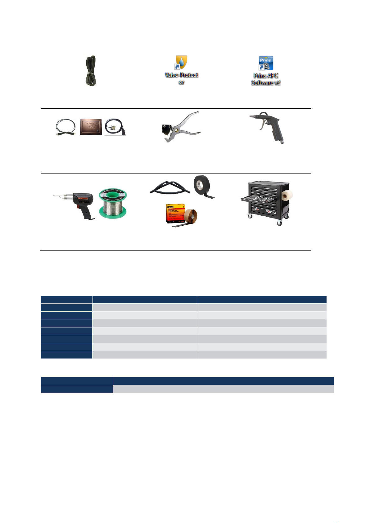
Tool requirements 6
Cable diagnostic ValveCare-DI
099/040003
ValveCare-DI software
Prins Diagnostic program V2.0
Tool kit PDT Diagnose
191/020001
Hose cutter
099/520024/A
Compressed air & air gun
Soldering iron & soldering tin
Insulating tape & adhesive
shrink sleeve
Basic workshop
equipment/tools
Abbreviations and terms7
Abbreviations7.1
Abbreviations
Out written
Explanation
AD
Analog digital
Sensor input
AFC
Alternative Fuel Controller
LPG computer
DI
Direct injection
Fuel injection in cilinder chamber
DIG IN
Digital Input
Input of on / off signal (high / low)
MPI
Multi Point Injection
Fuel injection in inlet manifold
VSI
Vapour Sequential Injection
Gas conversion systems for engines
DLM
Direct LiquiMax
Terms7.2
Terms
Explanation
Prins AFC Software V2
Name of the calibration, service and diagnostic program
Table of contents
Other Prins Automobile Accessories manuals


Popular Automobile Accessories manuals by other brands


ULTIMATE SPEED
ULTIMATE SPEED 279746 Assembly and Safety Advice

SSV Works
SSV Works DF-F65 manual

ULTIMATE SPEED
ULTIMATE SPEED CARBON Assembly and Safety Advice

Witter
Witter F174 Fitting instructions

WeatherTech
WeatherTech No-Drill installation instructions

TAUBENREUTHER
TAUBENREUTHER 1-336050 Installation instruction