AEREX Reco-Boxx 750 ZXR Troubleshooting guide
www.aerex.de© AEREX March – 2021
Operation and maintenance instructions
Operation and maintenance instructions
Reco-Boxx ZXR / ZXA / Flat

2www.aerex.de
Reco-Boxx ZXR / ZXA / Flat – Operation and maintenance instructions [03/
2021
]
Table of content
1.0 Operation and maintenance instructions ..................................................................................................... 3
2.0 Basic safety instructions .............................................................................................................................. 4
2.1 Intended use ........................................................................................................................................ 4
2.2 Specialist installer qualifications .......................................................................................................... 4
2.3 Non-intended use ................................................................................................................................ 4
2.4 Safety instructions ............................................................................................................................... 5
3.0 Symbols and abbreviations .......................................................................................................................... 8
4.0 Product overview ......................................................................................................................................... 9
4.1 General overview .................................................................................................................................. 9
4.2 Air volumes and dimensions Reco-Boxx ZXR / Flat-H ........................................................................ 11
5.0 Wiring overview ............................................................................................................................................ 12
5.1 Main control board TAC5 DG ............................................................................................................... 12
5.1.1 Reco-Boxx with counterflow ZXR / ZXA and Flat ..................................................................... 12
5.2 Circuit board SAT3 ............................................................................................................................... 14
5.3 Circuit board SAT BA/KW .................................................................................................................... 13
6.0 Functions ................................................................................................................................................... 14
6.1 Operating mode ................................................................................................................................... 14
6.2 Temperature control ............................................................................................................................. 15
6.3 Free cooling .......................................................................................................................................... 15
6.4 Change over function ........................................................................................................................... 16
6.5 Frost protection .................................................................................................................................... 17
6.6 Time schedule ...................................................................................................................................... 18
7.0 Commissioning ............................................................................................................................................. 19
7.1 Commissioning with Touchscreen TP-Touch ........................................................................................ 20
7.1.1 Home screen ............................................................................................................................. 21
7.1.2 Main menu ................................................................................................................................ 22
7.1.3 Basic Setup ............................................................................................................................... 24
7.1.4 Advanced setup ........................................................................................................................ 27
8.0 Preventive maintenance ................................................................................................................................ 34
8.1 Once the unit operates in normal condition ......................................................................................... 34
8.2 Every 3 months ..................................................................................................................................... 34
8.3 Every 12 months ................................................................................................................................... 35
9.0 Troubleshooting ............................................................................................................................................ 36
9.1 Troubleshooting .................................................................................................................................... 36
…
9.22 Troubleshooting .................................................................................................................................... 50
10.0 Parameters/Commissioning Sheet ............................................................................................................... 51
10.1 Main parameters after commissioning ................................................................................................. 51
10.2 Track changes ....................................................................................................................................... 52

3www.aerex.de
Reco-Boxx ZXR / ZXA / Flat – Operation and maintenance instructions [03/
2021
]
1.0 Operation and maintenance instructions
Applicable for the following units
Exchanger Sizes Integrated
pre-heating
Integrated
post-heating Handing Fan
Reco-Boxx ZXR
Counterflow
1000/1600/1800/2300/
2700/2900/3200/4200/
4700/6200/7000
Yes, electrical Yes, electrical
or water Left / Right Backward
(BW)
Reco-Boxx ZXA
Counterflow
900/1500/1900/
2500/2800/3700 Yes, electrical Yes, electrical
or water Left / Right Backward
(BW)
Reco-Boxx Flat-H
Counterflow
550/650/1000/1400/1700/
2100/2500/2700/3300/3700 Yes, electrical Yes, electrical
or water Left / Right Backward
(BW)
Reco-Boxx Flat
Counterflow
450/600/1000/
1300/1600/2000 Yes, electrical No Left / Right Forward
(FW)

4www.aerex.de
Reco-Boxx ZXR / ZXA / Flat – Operation and maintenance instructions [03/
2021
]
2.0 Basic safety instructions
2.1 Intended use
This ventilation unit with heat recovery is used in
centralised or decentralised ventilation systems.
The unit provides controlled ventilation and air
extraction in, for example, oces, school class-
rooms and other similar spaces. The units are
intended for ceiling-mounted installation because
they have outside air/outgoing air sockets on
the sides and/or discharging upwards. Please
note that the unit is very heavy, weighing approx.
210kg. The unit may only be used if installed
permanently, in dry indoor spaces and with
connected ventilation ducts. DN 250 connection
for geniovent.x 600 H and DN 315 connection
for geniovent.x 900 H. The units do not have unit
switches. Scope for completely disconnecting
the unit from the power supply should be pro-
vided by the customer. These ventilation units
are only intended for domestic use and similar
purposes. No other or additional use is intended.
2.2 Specialist installer qualifications
The ventilation unit may only be installed, set up,
retrofitted, started up, cleaned and maintained
by a trained specialist in accordance with these
instructions. You are deemed a trained spe-
cialist if your education, training or experience
in ventilation technology mean that you can
competently and safely undertake installation in
accordance with the planning requirements and
these instructions and are able to recognise and
avoid risks resulting from incorrect installations
and settings and the dangers resulting from
them. Only a qualified electrician is permitted to
work on the electrics. You are deemed a qualified
electrician if you are familiar with the relevant
standards and guidelines, can competently and
safely create electrical connections in line with
the attached wiring diagram and are able to
recognise and avoid risks and dangers associat-
ed with electricity on the basis of your technical
training and experience. Repair work may only be
undertaken by an authorised AEREX specialist.
After successful installation and commissioning,
instruct users in the ventilation unit and associat-
ed control unit.
2.3 Non-intended use
The ventilation unit must not be used in the fol-
lowing situations under any circumstances. Read
all the safety instructions.
Risk of combustion/fire from flammable ma-
terials, liquids or gases in the vicinity of the
ventilation unit. Do not place any flammable ma-
terials, liquids or gases near the ventilation unit,
which may ignite in the event of heat or sparks
and catch fire.
Risk of death if an air-ventilated fireplace is
connected to an exhaust gas system, which
itself has multiple connections. The air-venti-
lated fireplace may result in exhaust fumes being
transferred to other living units. Risk of death, for
example from carbon monoxide. Never use the
ventilation unit if there are air-ventilated fireplaces
in the living unit that are connected to exhaust
gas systems, which themselves have multiple
connections.
Explosion hazard. Explosive gases and dust
may ignite and cause serious explosions or fire.
Never use ventilation unit in an explosive atmos-
phere.
Explosion hazard. Explosive substances in lab
extraction units may ignite and cause serious
explosions or fire. Aggressive substances may
damage the ventilation unit. Never use ventilation
unit in combination with a lab extraction unit.
Risk to health from chemicals or aggressive
gases/vapours. Chemicals or aggressive gases/
vapours may present a risk to health, especially
if the ventilation unit distributes them into rooms.
Never use the ventilation unit to convey chemi-
cals or aggressive gases/vapours.
Damage to the unit.
• If operated during the build phase, potential
damage to unit caused by contamination of
the ventilation unit and ventilation ducts. Venti-
lation unit operation is not permitted during the
build phase
• Grease and oil vapours from range hoods may
contaminate the unit and ventilation ducts
and reduce eciency. Never use ventilation
unit in combination with range hoods, that are
connected directly to the controlled domestic
ventilation exhaust air channel. In rooms with

5www.aerex.de
Reco-Boxx ZXR / ZXA / Flat – Operation and maintenance instructions [03/
2021
]
greasy exhaust air, e.g. kitchens, only use
ventilation valves with a grease filter. Recom-
mendation: In terms of energy consumption,
use range hoods in circulating air mode.
• Corrosion of metal parts inside the ventilation
unit by additional components in the exhaust
duct. Do not use components which aect
temperature, humidity or air volumes on the
exhaust duct, for example if a drying cabinet is
connected to the exhaust duct.
2.4 Safety instructions
Read and observe all the safety instructions.
Risks for those who are not trained spe-
cialists, children and persons with reduced
physical, sensory or mental capabilities or a
lack of knowledge. Ventilation unit may only be
installed, commissioned, cleaned and maintained
by persons who can safely recognise and avoid
the risks associated with this work.
Risk to health if filters are not replaced or if
there are no air filters. Heavily soiled or moist
air filters can accumulate harmful substances
(mould, germs, etc.). This may also happen if the
ventilation unit is shut down for an extended pe-
riod. If there are no air filters, the ventilation unit
and ventilation ducts become dirty. Unfiltered
substances may enter the rooms.
• Never operate ventilation unit without air filters.
• Only use original filters.
• Recommendation: continuous operation.
• Observe filter change display. Change the air
filter every 6 months.
• If the ventilation unit has not been used for a
long time, always replace the air filters.
Risk to health if ventilation unit is not correct-
ly cleaned/maintained.
Clean/service the ventilation unit regularly, at
least every 2 years. This is the only way of ensur-
ing that the ventilation unit is running hygienically.
Risk of death from toxic air and air containing
pollutants (smoke, vapours) in the surround-
ing area – in the event of a fire or chemicals
accident etc. Switch the entire ventilation sys-
tem o immediately until the outside air is safe
again.
Risk during transport from heavy or falling
loads.
• Observe applicable safety and accident pre-
vention requirements.
• Note permissible maximum loading capacity of
lifting gear.
• Do not stand under a suspended load.
• Exercise caution when lifting. Note transport
weight (ventilation unit 210 kg) and centre of
gravity of ventilation unit (centre).
• Only transport ventilation unit to installation
site using suitable means of transport (e.g.
a lifting fixture) and with the help of several
people.
• Check unit for transport damage. Do not com-
mission a damaged unit.
Risk from inadequate load-bearing capacity of
the base/ceiling construction. Only install ven-
tilation unit on a base/ceiling construction with an
installation/attachment surface with an adequate
load-bearing capacity (at least 300 kg/m²).
Risk of injury from handling pointed housing
parts or those with sharp edges, e.g. on hous-
ing panels, railings, mounting feet or pointed
parts of front doors. Wear protective gloves.
Risk of injury if work is carried out by unquali-
fied sta. Specialist knowledge is needed for the
safe transport, installation, electrical connection
and commissioning of the ventilation unit. Only
have this work carried out by a specialist installer
or qualified electrician.
Risk of injury when working at heights.
Risk of injury when working at heights. Use ap-
propriate climbing aids (ladders). Stability should
be ensured, if necessary have the ladders stead-
ied by a 2nd person. Ensure that you are stand-
ing securely and cannot lose your balance and
that there is no one under the ventilation unit.
Danger of injury from damaged ventilation
unit. Switch the ventilation unit o immediately if
you discover damage or faults that could endan-
ger persons or property. Prevent further use until
the issue has been fully rectified.
Intended operation not ensured if installed in-
correctly. A ventilation unit not installed correctly
may result in operation not as intended.

6www.aerex.de
Reco-Boxx ZXR / ZXA / Flat – Operation and maintenance instructions [03/
2021
]
• Only install ventilation unit in accordance with
the planning documents.
• In particular, note the information on insulating
ventilation channels and sound deadening.
Recommendation: Use tubular sound absorber
for sound-deadened installation of ventilation
unit.
Risks from parts which may aect the ventila-
tion system which are added or modified at a
later date.
• Parts (range hood, air-ventilated fireplace etc.)
which are added or modified at a later date
may result in health risks and operation which
is not permitted.
• Parts may only be added or modified at a later
date if system compatibility is established/en-
sured by a planning oce. If using an exhaust
air range hood or air-ventilated fireplace, this
must be accepted by a regional master chim-
ney sweep.
Risk from operating with ventilation unit not
fully installed (open unit / without ventilation
ducts).
• Running fans can be touched. Electric compo-
nents are a potential source of electric shock.
Danger of burning on units with a heat register.
• If the ventilation unit is open, all the supply
circuits must be switched o (mains fuse o),
secured against being accidentally switched
back on and a visible warning sign must be
attached.
• Only operate ventilation unit if fully installed, if
all ventilation ducts are attached and the front
doors are closed.
• Do not reach into running fans.
• The heat register and/or protective grilles
of the heat register may be very hot. Before
touching, check whether heat registers and/or
protective grilles are still hot. Do not touch hot
surfaces.
Risk of injury if unit components (heat reg-
ister, heat exchanger etc.) fall down during
removal. Sometimes these can be hard to pull
out/slide in.
• Ensure that you are standing securely and
cannot lose your balance and that there is no
one under the unit.
• When removing and installing the components,
support them from below with a hand.
Risk of injury and health risk when using
accessory elements which have not been
approved.
The ventilation unit is tested with original ac-
cessories and components (e.g. air filter, heat
register, heat exchanger).
• The unit may only be operated with original
components.
• Modifications and alterations to units are not
permitted and release the manufacturer from
any guarantee obligations and liability.
Danger of electric shock.
Before opening the front doors and installing
the electrics, switch o all supply circuits and
secure them against being accidentally switched
back on again. Attach a warning sign in a clearly
visible place.
Danger if the relevant regulations for electri-
cal installations are not observed.
• Before removing the electronics cover and
installing the electrics, switch o all supply cir-
cuits and secure them against being acciden-
tally switched back on again. Attach a warning
sign in a clearly visible place.
• Be sure to observe the relevant regulations for
electrical installation; e.g. DIN EN 50110-1. In
Germany, particularly observe VDE 0100, with
the corresponding sections.
• A mains isolation device with contact openings
of at least 3 mm at each pole is mandatory.
• Only connect the ventilation unit to a perma-
nent electrical installation.
• Units may only be operated using the voltage
and frequency shown on the rating plate.
Damage to unit in the event of moisture in-
gress.
The ventilation unit has IP 40 degree of protec-
tion.
• Do not install ventilation unit outdoors.
• Protect ventilation unit from moisture and
wetness
Exercise caution when handling packaging
materials.
Store packaging material out of the reach of
children.

7www.aerex.de
Reco-Boxx ZXR / ZXA / Flat – Operation and maintenance instructions [03/
2021
]
Risk of death when operating with air-ventilat-
ed fireplaces. Ensure sucient supply air intake
during operation with air-ventilated fireplaces.
Note maximum permissible pressure dierence
per residential unit. The consent of a professional
chimney sweep is needed in all cases. Ventilation
units may only be installed in rooms, apartments
or housing units of a comparable size, in which
air-ventilated fireplaces are installed if:
• a parallel operation of air-ventilated fireplaces
for liquid or gaseous fuels and the air-extract-
ing equipment can be prevented via safety
devices, or
• the extraction of exhaust gas from the air-ven-
tilated fireplaces is monitored by a special
safety device. In the case of air-ventilated fire-
places for liquid or gaseous fuels, the fireplace
or the ventilation system must be switched
o if the safety device is triggered. In the case
of air-ventilated fireplaces for solid fuels, the
ventilation system must be switched o if the
safety device is triggered. In order to permit
the intended operation of ventilation systems
equipped with the central ventilation units with
heat recovery, it must be possible to shut o
any combustion air ducts or exhaust gas ducts
from air-ventilated fireplaces. For exhaust gas
ducts of fireplaces for solid fuels, the shut-o
device may only be operated by hand. It must
be possible to identify the position of the shut-
o device from the setting of the operating
handle. This is considered to be fulfilled if a
soot blocking device is deployed.

8www.aerex.de
Reco-Boxx ZXR / ZXA / Flat – Operation and maintenance instructions [03/
2021
]
3.0 Symbols and abbreviations
BW BACKWARD
CURVED FAN FW FORWARD
CURVED FAN
BF BAG FILTER PF PLEATED FILTER
RX REDARY HEAT
EXCHANGER PX PLATE HEAT
EXCHANGER
WARNING
Must be connected by a qualified Electrician.
Warning! Hazardous voltage.
OUTDOOR AIR Air from outdoor to the AHU
SUPPLY AIR Air from the AHU to the building
EXTRACT AIR Air from the building to the AHU
EXHAUST AIR Air from the AHU to outdoor
COOLING COIL BA-
NV / KW HEATING COIL
(WATER/ELECTRICAL)
SILENCER GD CTm MOTORISED
DAMPER
PRESSURE SENSOR P Tx TEMPERATURE SENSOR
No = x (1,2,3…)
SLIP CLAMP SC MS FLEXIBLE
CONNECTION
CIRCULAR DUCT CONNECTION ER For inlet SR For outlet

9www.aerex.de
Reco-Boxx ZXR / ZXA / Flat – Operation and maintenance instructions [03/
2021
]
4.0 Product overview
4.1 General overview
ATTENTION
Right and left hand units have dierent article numbers and should be ordered accordingly.
Main version described in the manuals is always the hand right version.
Right hand unit (supply air to the right) Left hand unit (supply air to the left)
Reco-Boxx ZXR-R Reco-Boxx ZXR-L
Reco-Boxx Flat-H-R (BOTTOM view) Reco-Boxx Flat-H-L (BOTTOM view)
Außenluft
Abluft
Zuluft
Fortluft Rechtsversion Linksversion
Außenluft
Abluft
Zuluft
Fortluft Rechtsversion Linksversion
Reco-Boxx ZXA-R 900/1500/1900 Reco-Boxx ZXA-L 900/1500/1900
Außenluft
Abluft
Zuluft
Fortluft Rechtsversion Linksversion
Außenluft
Abluft
Zuluft
Fortluft Rechtsversion Linksversion
Reco-Boxx ZXA-R 2500/2800/3700 Reco-Boxx ZXA-L 2500/2800/3700
ATTENTION: The dierence between left and right LP units is the factory placement of the controls box on
opposite sides.

10 www.aerex.de
Reco-Boxx ZXR / ZXA / Flat – Operation and maintenance instructions [03/
2021
]
Reco-Boxx ZXR
Reco-Boxx Flat-H
Reco-Boxx ZXA
Note: internal electrical coils, motorised dampers, internal fan-pressure sensors, flexible connections
and slip-clamps must ordered and are all pre-installed and factory wired. The internal heating
water-coil accessory is pre-installed, but must be connected, hydraulically and electrically, by the
installer.
1. Main switch for power supply AHU
2. Main switch for power supply electrical coils
(both internal pre-hating and post-heating)
3. Electrical cabinet
4. Supply fan
5. Extract fan
6. DDM-Set for CA-airflow measurement (option)
7. Outdoor air filter (bag or pleated)
8. Extract air filter (bag or pleated)
9. Heat exchanger
10. Modulating 100% bypass
11. Drain pan and drain pipe
12. Preheating coil (accessory for
Counterflow-equipments)
13. Internal post-heating water or electrical coil
(accessory)
14. Motorised damper (accessory)
15. Motorised damper (accessory))
16. Access panel (Flat only)
17. Flexible sleeve (accessory)
18. Slip clamp (accessory)
19. Water connection for post-heating (accessory)

11www.aerex.de
Reco-Boxx ZXR / ZXA / Flat – Operation and maintenance instructions [03/
2021
]
4.2 Air volumes and dimensions
Exchanger Volumetric
flow
[m³/h]
Pressure
reserve
[Pa]
Dimensions
(B x H x T)
[mm]
Duct
connection
[mm]
Automatic
Bypass valve
Pre / post
heating
inte-
grable
External,
optional
heating and / or
cooling register
controllable
Reco-Boxx 750 ZXR 200 – 800 800 – 190 1680 x 1465 x 610 DN 315 0 – 100% modulating YES YES
Reco-Boxx 1000 ZXR 200 – 1050 800 – 390 1680 x 1465 x 610 DN 315 0 – 100% modulating YES YES
Reco-Boxx 1300 ZXR 200 – 1380 830 – 420 1680 x 1465 x 815 DN 400 0 – 100% modulating YES YES
Reco-Boxx 1600 ZXR 200 – 1680 830 – 210 1680 x 1465 x 815 DN 400 0 – 100% modulating YES YES
Reco-Boxx 1800 ZXR 250 – 1860 690 – 200 1680 x 1465 x 995 DN 400 0 – 100% modulating YES YES
Reco-Boxx 2300 ZXR 400 – 2300 800 – 420 1680 x 1465 x 1182 1060 x 540 0– 100% modulating YES YES
Reco-Boxx 2700 ZXR 400 – 2800 800 – 240 1680 x 1465 x 1182 1060 x 540 0– 100% modulating YES YES
Reco-Boxx 2900 ZXR 300 – 3000 800 – 230 1680 x 1465 x 1382 1265 x 540 0– 100% modulating YES YES
Reco-Boxx 3200 ZXR 300 – 3230 770 – 200 1680 x 1465 x 1640 1520 x 540 0– 100% modulating YES YES
Reco-Boxx 4200 ZXR 300 – 4200 901 – 290 1880 x 1465 x 2015 1895 x 540 0– 100% modulating YES YES
Reco-Boxx 4700 ZXR 600 – 4700 1000 – 210 2557 x 1825 x 1640 1520 x 670 0– 100% modulating YES YES
Reco-Boxx 6200 ZXR 600 – 6260 890 – 300 2557 x 1825 x 2015 1895 x 670 0– 100% modulating YES YES
Reco-Boxx 7000 ZXR 600 – 7000 880 – 220 2557 x 1825 x 2396 2275 x 670 0– 100% modulating YES YES
Exchanger Volumetric
flow
[m³/h]
Pressure
reserve
[Pa]
Dimensions
(B x H x T)
[mm]
Duct connection
[mm]
Automatic
Bypass valve
Pre / post
heating
inte-
grable
External,
optional
heating and / or
cooling register
controllable
Reco-Boxx 550 Flat-H 100 – 550 1010 – 210 1300 x 350 x 890 DN 200 0 – 100% modulating YES YES
Reco-Boxx 650 Flat-H 100 – 650 1020 – 180 1300 x 350 x 1100 DN 250 0 – 100% modulating YES YES
Reco-Boxx 1000 Flat-H 200 – 1000 800 – 460 2100 x 435 x 1050 DN 315 0 – 100% modulating YES YES
Reco-Boxx 1400 Flat-H 400 – 1400 760 – 320 2100 x 435 x 1300 DN 315 0 – 100% modulating YES YES
Reco-Boxx 1700 Flat-H 400 – 1800 610 – 220 2100 x 435 x 1600
Connection on the suction
side (AU/AB): 800 x 300
Connection on the pressure
side (ZU/FO): 400 x 300
0– 100% modulating YES YES
Reco-Boxx 2100 Flat-H 400 – 2200 610 – 180 2250 x 510 x 1700
Connection on the suction
side (AU/AB): 800 x 400
Connection on the pressure
side (ZU/FO): 500 x 400
0– 100% modulating YES YES
Reco-Boxx 2500 Flat-H 400 – 2550 810 – 270 2250 x 510 x 1700
Connection on the suction
side (AU/AB): 800 x 400
Connection on the pressure
side (ZU/FO): 500 x 400
0– 100% modulating YES YES
Reco-Boxx 2700 Flat-H 400 – 2850 810 – 200 2250 x 510 x 1940
Connection on the suction
side (AU/AB): 1000 x 400
Connection on the pressure
side (ZU/FO): 500 x 400
0– 100% modulating YES YES
Reco-Boxx 3300 Flat-H 400 – 3300 770 – 230 2800 x 660 x 1935 Connection on the suction
side (AU/AB): 700 x 500
Connection on the pressure
side (ZU/FO): 700 x 500
0– 100% modulating YES YES
Reco-Boxx 3700 Flat-H 400 – 3700 1020 – 360 2800 x 660 x 1935 Connection on the suction
side (AU/AB): 700 x 500
Connection on the pressure
side (ZU/FO): 700 x 500
0– 100% modulating YES YES
Exchanger Volumetric
flow
[m³/h]
Pressure
reserve
[Pa]
Dimensions
(B x H x T)
[mm]
Duct
connection
[mm]
Automatic
Bypass valve
Pre / post
heating
inte-
grable
External,
optional
heating and / or
cooling register
controllable
Reco-Boxx 900 ZXA 200 – 940 380 – 790 1680 x 1465 x 610 DN 250 0 – 100% modulating YES YES
Reco-Boxx 1500 ZXA 200 – 1500 300 – 840 1680 x 1465 x 815 DN 315 0 – 100% modulating YES YES
Reco-Boxx 1900 ZXA 300 – 1900 300 – 810 1960 x 1725 x 815 DN 315 0 – 100% modulating YES YES
Reco-Boxx 2500 ZXA 300 – 2550 280 – 800 1960 x 1725 x 995 500 x 300 0 – 100% modulating YES YES
Reco-Boxx 2800 ZXA 300 – 2850 250 – 850 1960 x 1725 x 1182 600 x 300 0 – 100% modulating YES YES
Reco-Boxx 3700 ZXA 400 – 3700 360 – 980 1960 x 1725 x 1382 800 x 300 0 – 100% modulating YES YES
12 www.aerex.de
Reco-Boxx ZXR / ZXA / Flat – Operation and maintenance instructions [03/
2021
]
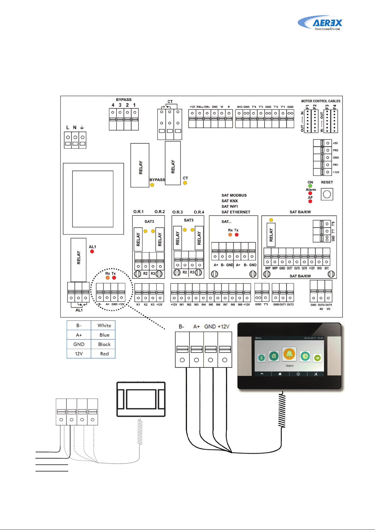
Wiring
The cables used must conform to the RS-485 Standard with twisted pair conductors. The cables must be
shielded. Conductor Area 0.2 mm². The total length must not exceed 100 meters.
Electrical cable: Installers need to foresee extra electrical cable length for easier future maintenance of the AHU.
TAC5 DT
CID 026001
S: 2.8.2
(und höher)
TAC5 DG
CID 026000
S: 2.7.0
(und höher)
LN
F3
F4
F1
F2
MOTORCONTROL CABLES
OUT IN
NITUO
OUT2
OUT1
GND
Alarm
ON
AF
AL1
AL1
RELAY
K1 K2 K3
+12V
IN1+12V IN2 IN3 IN4IN5 +12VIN6 IN7IN8 IN9
BYPASS
RELAY
CT
RELAY
xRxT
B- A+ GND
+12V
GNDT°5
BYPASS
43 21 CT
O.R.1O.R.2 O.R.3O.R.4
GNDOUT4OUT5
NV VO
GNDGNDT°1T°4T°3 GNDT°2
KWout
KW
in
+12V
VIGND
SAT BA/KW
SATMODBUS
+5V
PR3
GND
PR1
+12V
RESET
IN12
R
RELAY
B- A+ GND
+12V
TAC5DT/DG
Red
Black
White
Blue
Blue,Bleu,Blauw,Blau
B-
A+
Black,Noir,Zwart,Schwar
z
GND
Red,Rouge,Rood,Rot 12V
If DDM-Set present: -SiprésenceduDDM-Set:
Wenn das DDM-Setvohanden ist:
White,Blanc,Witte,Weiß
B- A+ GND
+12V
DDM-Set
Green
Red
Black
Yellow
GND
+24V/OUT5
Blue,Bleu,Blauw,Blau
B-
A+
Black,Noir,Zwart,Schwar
z
GND
Red,Rouge,Rood,Rot 12V
White,Blanc,Witte,Weiß
+12V
F2
NITUO
MOTORCONTROL CABLES
LN
R1
RELAY
SATCOM
SAT BA/KW
SAT3
O.R.1 O.R.2
RESET
ON
Alarm
AF
BYPASS
SETUP ENTER
DISPLAY
GND T°1T°2 T°3GNDT°5 GND +12V K1 K2 K3 +12VIN1 IN2 IN3 IN4
PR1 GND PR2 +5V
F1
IN
OUT
R
A+
B-
+12V
TAC5DM
Red
Black
White
Blue
If DDM-Set present: -SiprésenceduDDM-Set:
Wenn das DDM-Setvohanden ist:
DDM-Set
Green
Red
Black
Yellow
GND
+24V/OUT5
GND
A+
B-
+12V
GND
A+
B-
+12V
Touchpanel
Touchpanel
Touchpanel
Touchpanel
5.0 Wiring overview
5.1 Main control board TAC5
5.1.1 Reco-Boxx with counterflow ZXR / ZXA and Flat

13www.aerex.de
Reco-Boxx ZXR / ZXA / Flat – Operation and maintenance instructions [03/
2021
]
5.2 Circuit board SAT3
The SAT3 circuit board is used for extra functions for
which inputs and outputs are not included as standard
in the control unit of the air handling unit. All outputs
are normally open (N.O.). Maximal load: 230VAC – 4A.
The circuit board SAT3 allows for signalling of the
following by means of a potential-free contact: (fig. 2)
• Fan status
• Dierential pressure alarm
• Heating demand
• Bypass status
Installation
SAT3 must be plugged onto the control board circuit
(see fig.1).
Attention: The SAT3 must be plugged in before
the circuit is powered. SAT must be plugged in
correctly, wrong positioning can damage both
circuits permanently.
5.3 Circuit board SAT BA/KW
SAT TAC5 BA/KW is a satellite circuit designed to be fitted
on the main control board. It permits control of external
coils.
Installation
The SAT BA/KW must be plugged onto the control board
circuit (see fig.3).
Attention: The SAT TAC5 BA/KW must be
plugged in before the circuit is powered. SAT
must be plugged in correctly, wrong positioning
can damage both circuits permanently.
Wiring
The terminals of the SAT BA/KW are displayed in fig.4
WP WP = Cooling demand (max. 30 V-2 A)
OUT7 = 0-10 V output to control heating- or change over capacity
OUT8 = 0-10 V output to control cooling capacity
OUT9 = PWM output to control electrical coil
T°7 = Heating coil frost protection sensor (T7)
T°8 = Cooling coil frost protection sensor (T8)
IN10 = Cooling OFF, (to force heating o use IN6)
IN11 = Input cooling/heating (open = heating, closed = cooling)
fig. 1
fig. 2
fig. 3
fig. 4

14 www.aerex.de
Reco-Boxx ZXR / ZXA / Flat – Operation and maintenance instructions [03/
2021
]
6.0 Functions
6.1 Operating mode
There are five main operating modes. The operating mode determines how the airflow or the fan torque is
modulated. The default operating mode is Airflow control. Exceptions are units equipped with backwards
fans without the Constant Air Kit or if Constant Torque mode has been selected in the product setup menu,
in both cases it is the fan torque that will be controlled and modulated.
In all the operating modes, the supply fan(s) will operate as per the assigned mode and parameters. The
exhaust fan(s) will operate according to the chosen percentage of the supply fan (%EXH/SUP ratio). The five
main operating modes are:
• 1 - Airflow control:
Flow control involves operating the air handling unit to keep the pre-set airflow constant. The speed of
the fans is automatically regulated to provide correct airflow even if the filters begin to become clogged,
air terminals are blocked, etc. Airflow control mode is advantageous, since the airflow always is exactly
as it was from the beginning. It should however be noted that everything that increases the pressure drop
in the ventilation system, such as blocking of air terminals and dust accumulating in filters, causes the
fans to run at a higher speed. This results in higher power consumption and may also cause discomfort
in the form of noise. There are three airflow setpoints to be configured by the user (m³h K1, m³h K2, m³h
K3).
• 2 - Torque control:
3 torque setpoints to be configured by the user (%TQ K1, %TQ K2, %TQ K3). The setpoint is configured
in % of the maximal torque. The torque control allows to vary the fan speed automatically, to provide a
variable airflow for demand controlled systems (DCV). This allows for demand controlled fan operation or
fan optimisation by a BMS system, mostly used in multi zone systems. This operation mode can partially
replace the constant pressure control when a duct pressure sensor hasn’t been installed.
• 3 - Demand control 0-10V:
The airflow is controlled by a 0-10 V signal. The control signal is connected to terminals K2&GND. The
assigned supply airflow is set as a percentage of a linear 0-10 V signal. The user defines the link with 4
parameters: Vmin, Vmax, m³h Vmin and m³h Vmax, applied to the following diagram. The demand control
mode is also available for modulating fan torque instead of airflow (relevant for backwards fans units
without Kit CA).
The principle is identical to the demand control mode operation with the dierence that Vmin and Vmax
are connected to a %TQ instead of m³/h.
• 4 - Pressure control:
The airflow automatically varies to provide constant pressure in the ducting system. This type of control is
also called VAV control (Variable Air Volume).
Pressure on supply: the airflow of the supply fan(s) is modulated to maintain a certain pressure Setting
constant. The pressure is measured by a pressure sensor located in the supply air duct.
Pressure on exhaust: the airflow of the exhaust fan(s) is modulated to maintain a certain pressure Setting
constant. The pressure is measured by a pressure sensor located in the extract air duct.
• 5 - MODE OFF:
This stops the AHU.

15www.aerex.de
Reco-Boxx ZXR / ZXA / Flat – Operation and maintenance instructions [03/
2021
]
6.2 Temperature control
There are several options available on Reco-Boxx units to ensure a comfortable temperature.
The options are controlled either via supply or extract air temperature.
Post heating options: Post cooling:
•internal electrical postheating coil EN (KWout) •external water cooling coil (BA-)
•internal water postheating coil WN (NV)
•external electrical postheating coil
•external water postheating coil (BA+)
Supply Air Temperature
Supply temperature control is the default setting. This involves keeping a constant supply air temperature
without consideration to the load in the premises. The supply air temperature is measured on sensor T5.
Extract Air Temperature
The default temperature control can be changed to Extract temperature control via the advanced setup.
The extract air temperature is measured on sensor T2. Extract air control involves keeping a constant
temperature in the extract air duct (premises), by controlling the supply air temperature. This provides a
uniform temperature in the premises regardless of the load. The internal sensor T2 can be replaced with
the optional external room temperature sensor.
Temperature sensor positioning:
Outside Inside
6.3 Free cooling
The free cooling function uses the lower temperature of the outside air to cool the building.
Free cooling is realized by means of the integrated 100% modulating bypass of the heat exchanger (PX)
or the stepless motor control of the rotary heat exchanger (RX). The optional output O.R.4 on the SAT3
relay indicates the position of the bypass. The contact will open if the bypass is fully closed, or close if
the bypass is fully or partially open.
The bypass (PX) or the rotary heat exchanger (RX) can be configured as on/o or modulating. This is con-
figured in ADVANCED SETUP. In modulating mode, the temperature is configured in the base setup and
the position of the bypass/stepless motor will modulate in order to maintain the setpoint. The free cooling
function is activated automatically.
An on/o bypass / stepless motor operates according to the logic below:
Free cooling STARTS if the following
conditions are TRUE:
•The outdoor temperature (sensor T1) is
lower than the extract air temperature
(sensor T2).
•The outdoor temperature (sensor T1) is
higher than 15°C.
•The extract air temperature (sensor T2) is
higher than 22°C.
Free cooling STOPS if one of the following
conditions is TRUE:
•The outdoor temperature (sensor T1) is
higher than the extract air temperature
(sensor T2).
•The outdoor temperature (sensor T1) is
lower than 14°C.
•The extract air temperature (sensor T2) is
lower than 20°C.
These Settings can be configured in ADVANCED SETUP
16 www.aerex.de
Reco-Boxx ZXR / ZXA / Flat – Operation and maintenance instructions [03/
2021
]
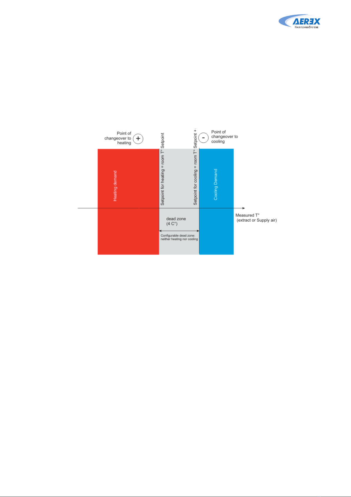
6.4 Change over function
4 PIPE AUTOMATIC CHANGE OVER
The TAC5 controller allows for the control of reversible coil or both cooling and heating coil. The coils are
equipped with their motorised 3-way valves. The oset between the measured temperature (supply air or
extract air, to be configured) and the setpoint will determine if heating or cooling is automatically acti-
vated. When the unit is equipped with reversible coil or with both a cooling and a heating coil, only one
setpoint has to be configured: Comfort temperature. The neutral band prevents the cooling and heating
systems from counteracting each other. The neutral band is added to the comfort setpoint for the activa-
tion of the cooling function. The neutral bands has to be configured in the advanced setup.

17www.aerex.de
Reco-Boxx ZXR / ZXA / Flat – Operation and maintenance instructions [03/
2021
]
6.5 Frost protection
HEATING COIL
The frost protection function is always active if the heating coil has been correctly configured in the
product setup. The monitoring function uses the temperature sensor T4 for the integrated coil (NV) or the
temperature sensor T7 for the external coil (EBA). The function is activated when the surface temperature
of the coil drops below 5°C. Under these conditions the pump output is activated and the three-way
valve output will be 100%. If after 15 minutes the surface temperature has not risen, the unit will shut
down and generate a frost alarm.
PLATE HEAT EXCHANGER (PX)
There are three strategies to protect the plate heat exchanger from freezing:
• 1 - Reduced supply air flow:
The heat exchanger is supplied with a frost protection sensor on the exhaust air (T3). If the exhaust air
temperature (T3) is >1°C and <+5°C:
• In airflow control mode and demand control, the supply air flow will modulate between 100% and
33% (AFlow)of the setpoint (AFn)
• pressure control mode, the supply air pressure will modulate between 100% and 50% (AFlow) of the
setpoint (AFn)
If the exhaust air temperature (T3) is <1°C, the supply air fans will stop until the exhaust air temperature
(T3) is >2°C for 5 minutes.
• 2 - Modulating bypass:
The modulating bypass is controlled by the exhaust temperature sensor (T3). If:
• Exhaust temperature (T3) >+1°C: bypass closed or controlled by free cooling function
• Exhaust temperature (T3) ≤ +1°C: bypass will modulate for the exhaust temperature (T3) to exceed
+1°C.
The corresponding supply air temperature will drop due to a lower airflow through the heat exchanger.
• 3 - Electrical preheating coil (accessory):
If an electrical pre-heating coil EV (KWin) is installed and configured, the pre-heating coil (KWin) will
modulate so the exhaust temperature is +1°C.
• 4 - Dierential pressure measurement (Cold climate option):
For cold climate conditions (≥-20⁰C), the unit is equipped with a dierential pressure sensor mounted
on the heat exchanger. The pressure sensor detects when the pressure drop, due to frost, has become
too high. In critical conditions, the supply air flow will be paused for a short time, to allow for defrost-
ing.
The frost protection strategy (down regulation supply airflow, modulating bypass or electrical pre-
heating) will still be used as a first step. The defrost function will only be active if the frost protection
strategy is not sucient.
These Settings can be configured in ADVANCED SETUP

18 www.aerex.de
Reco-Boxx ZXR / ZXA / Flat – Operation and maintenance instructions [03/
2021
]
6.6 Time schedule
The controller allows 6 time slots (channels) to be configured. For each day of the week, the operation
mode can be either AUTO (operate according to time slots) or OFF.
For each time slot select:
• In airflow control mode: the airflow by selecting m³h K1 / m³h K2 / m³h K3 / OFF (stop)
• In torque control mode: the torque by selecting %TQ K1 / %TQ K2 / %TQ K3 / OFF (stop)
• In demand control mode:
• with only one 0-10 V signal (default) or with 2 signals to control the supply airflow: the link LS
(percentage of the nominal link, cfr m³/h Vmin and m³/h Vmax in setup OR cfr %TQ Vmin and %TQ
Vmax in setup) and the rate of the exhaust airflow by the supply airflow.
• with one 0-10 V signal for supply and one 0-10 V signal for exhaust (via advanced setup): one link
LS (percentage of the nominal link) for supply and one for exhaust.
• In pressure control mode:
• Constant pressure on supply or exhaust: the pressure setpoint (percentage of the nominal setpoint)
and the rate of the exhaust airflow by the supply airflow.
• Constant pressure on supply and exhaust: one pressure setpoint (percentage of the nominal
setpoint) for supply and one for exhaust.
19www.aerex.de
Reco-Boxx ZXR / ZXA / Flat – Operation and maintenance instructions [03/
2021
]
7.0 Commissioning
As a human machine interface (HMI), several options are available. The HMI will enable access to the
control parameters in the integrated controller. The HMI as such does not contain any programming and
therefor is not mandatory.
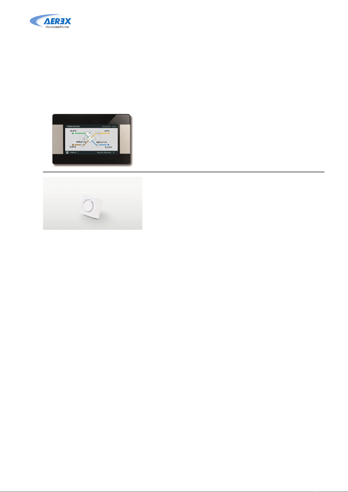
The possible HMIs are:
Touchpanel TP-Touch
This 4.3” touchscreen display is used when there is
a need for a graphical HMI. The Touchscreen touch-
screen is a complete graphic monitoring system
where the screens are designed to be intuitive and
complete, ensuring a userfriendly experience.
Position switch PCOM4
The most basic interface to control a GLOBAL air
handling unit is the 4 position swich. This swith will
allow to control the unit to its three configured airflow
(low, medium and high) and as a fourth position, the
unit is switched o.
20 www.aerex.de
Reco-Boxx ZXR / ZXA / Flat – Operation and maintenance instructions [03/
2021
]
7.1 Commissioning with Touchscreen TP-Touch
The hand-held terminal consists of a 4.3” touch screen with a 1,5 metre long cable for connection to the
air handling unit’s control circuit board.
If the hand-held terminal is not used for 20 minutes, it switches over to the sleep mode.
The Touchscreen controller can be used outdoors, but it must be kept at a weatherproof place.
Data:
Operating temperature: 0... + 50°C
Maximum length of the cable: >100 metres
Protection class: IP20
Dimensions [mm]: 96,8x148,8x14,5
Power consumption: 120mA
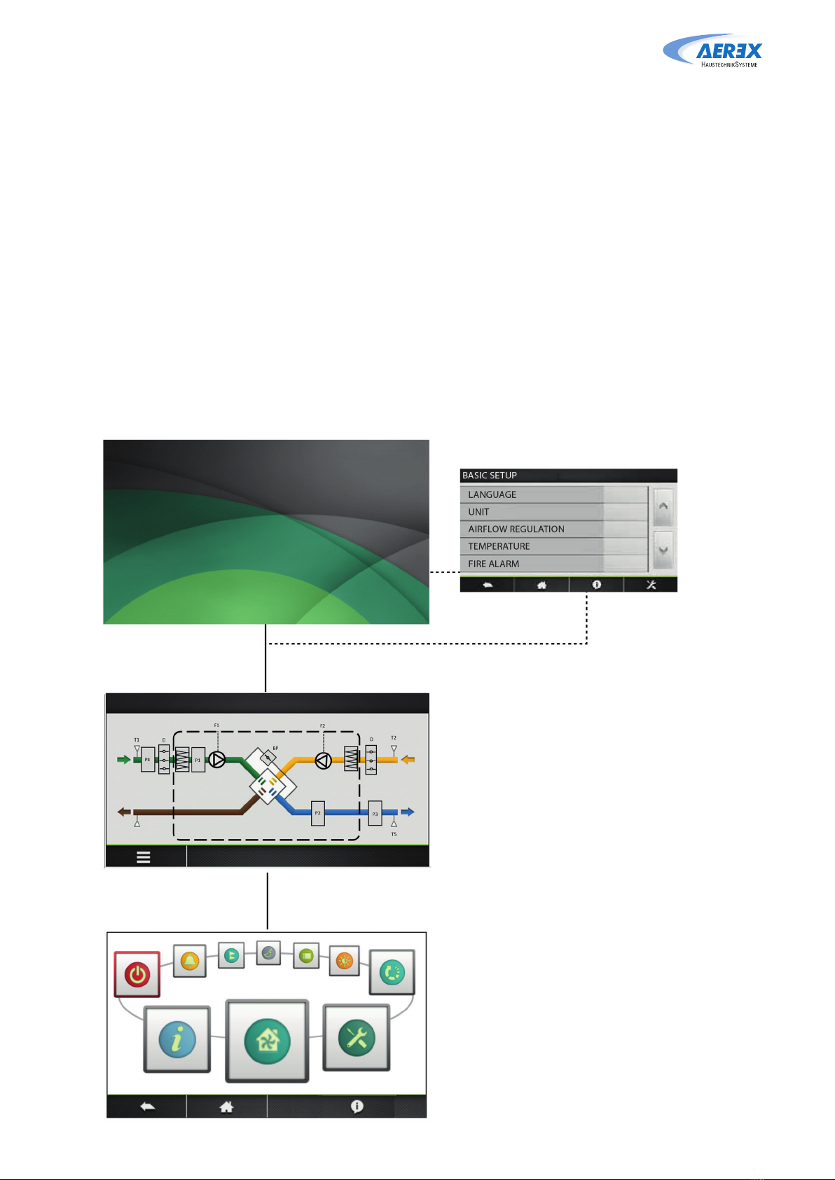
Image management
Start-up image
At the first start up, the basic setup menu will be
activated automatically. See section 7.1.3
Home Screen. See Section 7.1.1
By default, the home screen will be shown if no
other menu is opened by the user or if selected
in the main menu.
N.B.! The appearance of the image varies
depending on the type of air handling unit and
functions selected.
Main menu. See Section 7.1.2
The main menu is presented as a rotary menu.
After pressing the “menu”-button at the bottom
left corner of the Home Screen, the rotary menu
will be shown.
This manual suits for next models
48
Table of contents
Other AEREX Fan manuals

Popular Fan manuals by other brands

Emerson
Emerson CF943 owner's manual

Mitsubishi Electric
Mitsubishi Electric VL-100ZSKRT-E operating instructions

Harbor Breeze
Harbor Breeze E-TM52BNK5LED installation guide

Deltafan
Deltafan Ex instruction manual

Sonnenkonig
Sonnenkonig CHROM 16 user manual

Continental Electric
Continental Electric CE29502 instruction manual


RadonAway
RadonAway RP SERIES installation instructions

Vornado
Vornado Zippi owner's guide

Viking Range
Viking Range RDIPR101R manual

Neostar Electronics
Neostar Electronics 3209575 instruction manual

Komfovent
Komfovent DOMEKT ReGO 200VE-B Installation and maintenance manual

Vornado
Vornado OSCR32 user manual