manuals.online logo
Brands
  1. Home
  2. •
  3. Brands
  4. •
  5. AERMEC
  6. •
  7. Air Conditioner
  8. •
  9. AERMEC FCD Manual

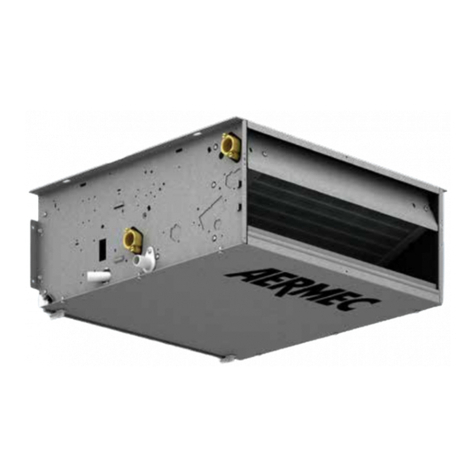
AERMEC FCD Manual

VENTILCONVETTORI
FAN COIL
VENTILO-CONVECTEURS
GEBLÄSEKONVEKTOREN
FCD
FCD-CT
IFCDFX
0201
64432.30
Sostituisce - Replace
Remplace - Ersetzt:
64432.26/9909
MM
MMAA
AANN
NNUU
UUAA
AALL
LLEE
EE
DD
DDII
II
FF
FFUU
UUNN
NNZZ
ZZII
IIOO
OONN
NNAA
AAMM
MMEE
EENN
NNTT
TTOO
OO
••
••
DD
DDII
IIRR
RREE
EECC
CCTT
TTII
IIOO
OONN
NNSS
SS
FF
FFOO
OORR
RR
UU
UUSS
SSEE
EE
MM
MMAA
AANN
NNUU
UUEE
EELL
LL
DD
DDEE
EE
FF
FFOO
OONN
NNCC
CCTT
TTII
IIOO
OONN
NNNN
NNEE
EEMM
MMEE
EENN
NNTT
TT
••
••
BB
BBEE
EEDD
DDII
IIEE
EENN
NNUU
UUNN
NNGG
GGSS
SSAA
AANN
NNLL
LLEE
EEII
IITT
TTUU
UUNN
NNGG
GG
INDICE • INDEX • INDEX • INHALTSVERZEICHNIS
FCD - CT
Caratteristiche • Features • Caracteristiques • Eigenschaften 3
Utilizzo • Operation 4
Utilisation • Betrieb 5
Caratteristiche di funzionamento • Operation 6
Caracteristiques de fonctionnement • Einsatzcharakteristik 7
FCD
Utilizzo • Operation • Utilisation • Betrieb 8
USI IMPROPRI • IMPROPER USES • USAGES IMPROPES • UNSACHGEMÄßER GEBRAUCH
MANUTENZIONE • MEINTENANCE • ENTRETIEN • WARTUNG
9
PROBLEMA - PROBABILE CAUSA - SOLUZIONE
PROBLEM - PROBABLE CAUSE - REMEDY
PROBLEME - CAUSE PROBABLE - SOLUTION
PROBLEM - MÖGLICHE URSACHE - ABHILFE
10
3
+
-
A
B
CD
VERSIONE CT (CON TERMOSTATO) • CT VERSION (WITH THERMOSTAT)
VERSION CT (AVEC THERMOSTAT) • VERSION CT (MIT REGELTHERMOSTAT)
Fig. 1
V1 =Velocità minima
Minimun fan speed
Vitesse minimale
Mindestgeschwindigkeit
V2 =Velocità media
Mediun fan speed
Vitesse moyenne
Mittlere Geschwindigkeit
V3 =Velocità massima
Maximun fan speed
Vitesse maximale
Höchstgeschwindigkeit
FF
FFCC
CCDD
DD
--
--
CC
CCTT
TT
Il pannello comandi è alloggiato sotto lo sportellino a destra
del ventilconvettore.
Il termostato di regolazione controlla il funzionamento del ven-
tilconvettore per mantenere nell’ambiente la temperatura impo-
stata.
Il modo di funzionamento in riscaldamento o in raffreddamento,
avviene in modo automatico (cambio stagione) e dipende dalla
temperatura dell’acqua circolante nell’impianto.
Il pannello comprende (fig. 1):
–(A) selettore acceso-spento e modo di ventilazione;
–(B) selettore della temperatura;
–(C) led indicatore del modo di funzionamento (blu, rosso e
fucsia);
–(D) led giallo indicatore di richiesta ventila-
zione (se lampeggiante indica anomalie di
funzionamento).
The control panel is located under the door on the right-hand
side of the fancoil.
The thermostat controls the operation of the fancoil, which is
regulated to maintain the temperature setting.
The unit operating mode switches automatically between hea-
ting and cooling (season change), depending on the tempera-
ture of the water in the system.
The panel features (fig. 1):
-(A) ON/OFF and ventilation mode selector switch;
-(B) temperature selector switch;
-(C) operating mode LED indicator lamp (blue, red and pink);
-(D)ventilation request yellow LED lamp (also indicates operating
fault when flashing).
Le panneau de commande se trouve sous le
volet, à droite du ventilo-convecteur.
Le thermostat de régulation contrôle le fonc-
tionnement du ventilo-convecteur, de façon à
maintenir constante la température pro-
grammée dans la pièce.
Le mode de fonctionnement Chauffage ou Rafraîchissement se
fait automatiquement (changement de saison) et il dépend de
la température de l'eau qui circule dans l'installation.
Le panneau comprend (fig. 1):
-(A) sélecteur marche-arrêt et mode de ventilation;
-(B) sélecteur de la température;
-(C) led indiquant le mode de fonctionnement (bleu,
rouge et fuchsia);
-(D) led jaune indiquant une demande de ventilation
(ou des anomalies de fonctionnement si elle clignote).
Das Bedienteil ist unter der rechten Klappe
am Gebläsekonvektor angebracht.
Der Temperaturregler steuert den Betrieb des
Gebläsekonvektors so, dass die eingestellte
Raumtemperatur konstant gehalten wird.
Die Einschaltung der Betriebsart Heizen oder
Kühlen erfolgt automatisch (Umschaltung von Heizen/Kühlen)
in Funktion der Temperatur des in der Anlage zirkulierenden
Wassers.
Auf dem Bedienteil sind folgende Elemente angeordnet (Abb. 1):
-(A) Wahlschalter Ein/Aus und Gebläsebetrieb;
-(B) Temperaturschalter;
-(C) Anzeige-Led der Betriebsart (blau, rot und fuchsia);
-(D)Gelbe Led zur Anzeige der Anforderung des
Gebläsebetriebs (oder Betriebsstörungen bei Blinken).
4
OPERATION
Controls
Speed selector switch (A)
Before switching on the "FCD-CT" version
fancoil, open the slats (fig. 2).
Speed selector switch (A)
OFF The fancoil is off, though will restart in hea-
ting mode (antifreeze function) if room temperatu-
re drops below 8°C and water temperature is suita-
ble; in this case, the red LED lamp will flash.
AUTO The thermostat maintains temperature of
the setting by adjusting fan speed in automatic
mode, according to the room temperature and the
temperature setting.
The thermostat maintains the temperatu-
re of the setting by on-off cycles, using
minimum, medium and maximum fan speeds as
required.
Temperature selector switch (B)
Use to make the required temperature setting (fig.
4).
The temperature at the central position (fig. 5) will
depend on the current operating mode (Heating
20°C, Cooling 25°C, Antifreeze 8°C).
The maximum temperature deviations from the
central position are +8°C and -8°C
Season change
The FCD-CT fancoil automatically sets to Heating or Cooling
mode according to the temperature of the water circulating
through the unit. In special cases, season change can be made
by adjusting the temperature selector switch.
Displays
The LED indicator lamp C changes colour to indicate the cur-
rent operating mode:
RED Heating,
BLUE Cooling,
PINK When flashing, water in unit has not yet reached
temperature required to enable ventilation,
YELLOW Ventilation request is activated. When flashing,
an ambient probe operating fault has been detected
(Emergency mode).
UTILIZZO
Comandi
Per accendere i ventilconvettori in versione
“FCD-CT”, prima aprire le alette (fig. 2).
Selettore della Velocità (A)
OFF Il ventilconvettore è spento. Può però ripar-
tire in modalità Caldo (funzione Antigelo) se la
temperatura ambiente diventa inferiore a 8°C e la
temperatura dell’acqua è idonea, in questo caso il
led rosso lampeggia.
AUTO Il termostato mantiene la temperatura impo-
stata cambiando la velocità del ventilatore in Modo
Automatico, in funzione della temperatura ambien-
te e di quella impostata.
Il termostato mantiene la temperatura
impostata mediante cicli di accensione e
spegnimento, utilizzando rispettivamente la velocità
minima, media o massima del ventilatore.
Selettore della Temperatura (B)
Consente di impostare la temperatura desiderata
(fig. 4).
La temperatura corrispondente al selettore imposta-
to nella posizione centrale (fig. 5), dipende dal
modo di funzionamento attivo (Caldo 20°C, Freddo
25°C, Antigelo 8°C).
Le differenze di temperatura massima e minima
rispetto alla posizione centrale sono +8°C e -8°C
Cambio stagione
Il ventilconvettore FCD- CT imposta automaticamente il fun-
zionamento a Caldo o a Freddo in funzione delle temperature
dell’acqua nell’impianto; per impostazioni particolari è possi-
bile il cambio stagione agendo sul selettore temperatura.
Visualizzazioni luminose
Il led C cambia di colore per indicare il modo di funziona-
mento attivo:
ROSSO Caldo (riscaldamento),
BLU Freddo (raffreddamento),
FUCSIA lampeggiante indica che l’acqua nell’impianto non
ha ancora raggiunto la temperatura idonea per
abilitare la ventilazione,
GIALLO acceso indica che la richiesta di ventilazione è attiva;
lampeggiante indica una anomalia di funzionamento
della sonda ambiente (Modo Emergenza).
Fig. 2
+
-
A
Fig. 3
+
-
20°C
12°C28°C
CD
+
-
CD
25°C
33°C
17°C+
-
8°C
8°C8°C
CD
FROST PROTECTION
Riscaldamento •Heating
Chaud •Warm Raffreddamento •Cooling
Froid •Kalt
Fig. 5
+
-
B
CD
Fig. 4
FF
FFCC
CCDD
DD
--
--
CC
CCTT
TT
5
UTILISATION
Commandes
Sur les appareils de la version "FCD-CT", avant
d'allumer les ventiloconvecteurs, ouvrir les ailettes
(fig. 2).
Sélecteur de la Vitesse (A)
OFF Le ventilo-convecteur est éteint. Il peut tou-
tefois repartir en mode Chauffage (fonction Antigel)
si la température ambiante s'abaisse au-dessous de
8°C et que la température de l'eau est appropriée;
dans ce cas, la led rouge se met àclignoter.
AUTO Le thermostat maintient la température pro-
grammée en modifiant la vitesse du ventilateur en
Mode Automatique, en fonction de la température
ambiante et de la température programmée.
Le thermostat maintient la température pro-
grammée en exécutant des cycles d'allu-
mage et d'arrêt et en utilisant respectivement la vitesse
minimale, moyenne ou maximale du ventilateur.
Sélecteur de la Température (B)
Il permet de programmer la température désirée
(fig. 3).
La température correspondant au sélecteur réglésur
la position centrale (fig. 5) dépend du mode de
fonctionnement actif (Chaud 20°C, Froid 25°C,
Antigel 8°C).
Les différences de température maximale et mini-
male par rapport àla position centrale sont +8°C et
-8°C.
Changement de saison
Le ventilo-convecteur FCD- CT règle automatiquement le
fonctionnement en Chauffage ou Rafraîchissement en fonction
de la température de l'eau présente dans l'installation; pour
des réglages particuliers, le changement de saison est possible
en agissant sur le sélecteur de température.
Visualisations lumineuses
La led C change de couleur pour indiquer le mode de fonc-
tionnement actif:
ROUGE Chaud (chauffage),
BLEU Froid (rafraîchissement),
FUCHSIA Si la led clignote, elle indique que l'eau présente
dans l'installation n'a pas encore atteint la tempé-
rature appropriée pour valider la ventilation,
JAUNE allumée, la led indique que la demande de ventilation
est active;
elle clignote pour indiquer une anomalie de fonction-
nement de la sonde ambiante (Mode Urgence).
BETRIEB
Bedienungselemente
Vor dem Einschalten der Gebläsekonvektoren
der Versionen "FCD-CT", müssen zunächst
die Klappen (Abb. 2) geöffnet werden.
Drehzahl-Wahlschalter (A)
OFF Der Gebläsekonvektor ist ausgeschaltet. Er
wird wieder in der Betriebsart Heizen (Einfrierschutz-
Funktion) eingeschaltet, sobald die Raumtemperatur
unter 8 °C abfällt und die Wassertemperatur dies
zulässt. In diesem Fall blinkt die rote Led-Diode.
AUTO Der Temperaturregler hält die eingestellte
Temperatur durch Regelung der Gebläsedrehzahl im
Automatikbetrieb in Funktion von Raumtemperatur
und eingestelltem Temperatur-Sollwert konstant.
Der Temperaturregler hält den eingestellten
Temperatur-Sollwert durch zyklisches Ein- und
Ausschalten konstant, er setzt dazu entweder die unterste,
die mittlere oder die höchste Gebläsedrehzahl ein.
Temperaturschalter (B)
Dieser Schalter dient zur Einstellung der gewünsch-
ten Raumtemperatur (Abb. 3).
Die Temperatur bei Mittelstellung des
Wahlschalters (Abb. 5) ist von der jeweils aktiven
Betriebsart abhängig (Heizen 20 °C, Kühlen 25 °C,
Einfrierschutz 8 °C).
Die Differenz der höchsten und niedrigsten
Temperatur zur Mittelstellung beträgt +8 °C und -8
°C.
Umschaltung Kühl-/Heizbetrieb
Der Gebläsekonvektor FCD-CT schaltet selbsttätig in Funktion
der Wassertemperaturen in der Anlage die Betriebsart Heizen
oder Kühlen ein. Für spezielle Einstellungen kann die
Umschaltung von Kühl-/Heizbetrieb mit dem
Temperaturschalter vorgenommen werden.
Leuchtanzeigen
Die Led-Diode C zeigt die jeweils aktive Betriebsart durch eine
Farbänderung an:
ROT Heizen (Heizung);
BLAU Kühlen (Kühlung);
FUCHSIA Durch Blinken wird angezeigt, dass die Wasserfüllung
der Anlage noch nicht die zur Einschaltung des
Gebläses erforderliche Temperatur erreicht hat.;
GELB Zeigt durch Leuchten an, dass der Betrieb des
Gebläses angefordert wurde.
Blinken zeigt eine Funktionsstörung des
Raumfühlers an (Notbetrieb).
Fig. 2
+
-
A
Fig. 3
+
-
B
CD
Fig. 4
FF
FFCC
CCDD
DD
--
--
CC
CCTT
TT
6
OPERATION
FCD-CT fancoils are delivered ready to operate in standard
configuration, though can be adjusted by the installation tech-
nician to specific requirements by means of dedicated accesso-
ries and configuration of functions at the internal dipswitches
(see INSTALLATION BOOKLET).
Response to controls is immediate, except in special cases.
Unit types
I ventilconvettori della serie FCD-CT sono progettati per
impianti a 2 tubi, nelle varianti:
- senza valvola;
- con valvola a 2 vie (sonda acqua a valle della valvola);
- con valvola a 3 vie (sonda acqua a monte della valvola).
Ventilazione
Ventilation speed can be controlled either manually by setting
the selector switch to position V1, V2 or V3 (the fan operates
in on-off cycles according to the speed selected), or automati-
cally when the selector switch is set to the AUTO position (fan
speed is controlled by the thermostat according to room tem-
perature detected).
In the case of units with water probe above the valve, an ope-
rating delay (maximum time 2'40") can be set between valve
start and fan enable (exchanger preheating).
Season change
The thermostat changes seasonal operation automatically.
Season change takes place according to the water tempera-
ture detected in the unit.
According to the dipswitch settings, two types of season
change (water side) are possible:
- with minimum/maximum temperature control only;
- with minimum/maximum temperature control and coil
preheating (fan operation delay maximum 2'40").
In the case of special units with water probe below the valve
or fitted with 2-way valve, season change takes place from the
air side, through operation of the temperature selector switch.
Though this setting allows use of the fancoil in pre-existing 2-
way units, it is not recommended, given that it hampers the
operation of the electronic thermostat (the Heating/Cooling
mode status display by LED is altered, depending on the tem-
perature selected and the room air temperature).
Water temperature controls
The thermostat only enables fan operation when the water
temperature is suitable for Heating or Cooling mode.
The enabling thresholds 35°C or 39°C (heating) and 17°C or
22°C (cooling) can be configured as required by means of the
dipswitches.
If the water temperature is not suitable for the operating mode
selected, LED lamp C on the control panel flashes alternately
pink, red and blue next to the relative mode.
If a 3-way valve is installed, replace the water probe SW (stan-
dard accessory) with the accessory SW3. Position the bulb of
the latter accessory on the delivery line above the valve.
Valve control
La valvola può essere controllata in due modalità:
- optimised: the valve opens or closes, depending on whether
the fan starts up or shuts down.
- normal: the valve opens or closes, depending on whether the
fan starts up or shuts down.
Emergency mode
In the event of fault in the ambient probe SA, the thermostat
sets to Emergency mode, indicated by the flashing of the yel-
low LED lamp (D). In this condition, the thermostat operates
as follows:
- with selector switch (A) in OFF position: water valve is clo-
sed and fan off;
- with selector switch (A) in AUTO, V1, V2 or V3 position: the
water valve remains open and the fan performs on - off cycles;
in this case, the power supplied by the terminal is controlled
manually by means of the selector switch (B): rotate the swit-
ch to right to increase cycle duration, or to the left to reduce it.
CARATTERISTICHE DI FUNZIONAMENTO
I ventilconvettori FCD-CT sono forniti pronti a funzionare in
configurazione standard, ma consentono all’installatore di
adeguarli alle necessitàspecifiche dell’impianto con accessori
dedicati e personalizzando le funzioni agendo sui Dip-Switch
interni (vedi MANUALE D’INSTALLAZIONE).
La risposta ai comandi èimmediata, tranne casi particolari.
Tipologie d’impianto
I ventilconvettori della serie FCD-CT sono progettati per
impianti a 2 tubi, nelle varianti:
- senza valvola;
- con valvola a 2 vie (sonda acqua a valle della valvola);
- con valvola a 3 vie (sonda acqua a monte della valvola).
Ventilazione
La ventilazione a tre velocitàpuòessere comandata sia
manualmente con selettore in posizione V1, V2 e V3 (il venti-
latore èutilizzato con cicli di acceso-spento sulla velocità
selezionata), oppure automaticamente con selettore in posizio-
ne AUTO (la velocitàdel ventilatore ègestita dal termostato in
funzione delle condizioni ambientali).
Per impianti con valvola e installazione Sonda Acqua a monte
della valvola èpossibile un ritardo (ventilazione ritardata fino
ad un massimo 2’40”) tra accensione valvola ed abilitazione
ventilatore (preriscaldamento scambiatore).
Cambio stagione
Il termostato cambia stagione automaticamente.
Il cambio stagione avviene in base alla temperatura dell’acqua
rilevata nell’impianto.
In funzione delle settaggio dei Dip èpossibile avere due modi
di cambio stagione dal lato acqua:
- con il solo controllo della temperatura minima/massima;
- con il controllo della temperatura minima/massima ed il pre-
riscaldamento della batteria (ventilazione ritardata fino ad un
massimo di 2’40”).
Solo per impianti particolari con sonda acqua a valle oppure
valvola a 2 vie, il cambio stagione avviene dal lato aria, agendo sul
selettore di temperatura; questa impostazione permette di poter uti-
lizzare il ventilconvettore in impianti a 2 vie presistenti, ma èscon-
sigliata in quanto riduce la facilitàd’uso del termostato elettronico
(la visualizzazione dello stato di funzionamento Caldo/Freddo tra-
mite led risulta alterata, dipende dalla temperatura selezionata e
dalla temperatura dell’aria nell’ambiente ).
Controlli sulla temperatura dell’acqua
Il termostato abilita la ventilazione solamente se la temperatu-
ra dell’acqua èidonea al modo Caldo o Freddo.
Le soglie di abilitazione 35°C o 39°C a caldo e 17°C o 22°C a
freddo sono configurabili tramite i Dip-Switch.
Il pannello comandi segnala la situazione in cui la temperatu-
ra dell’acqua non sia adeguata al modo di funzionamento
impostato, tramite il lampeggio alternato sul led C del colore
fucsia con i colori rosso o blu relativi al modo attivo .
Nel caso sia installata la valvola a 3 vie la sonda acqua SW (di
serie) dev’essere sostituita con l’accessorio SW3 il cui bulbo deve
essere posizionato sul tubo di mandata a monte della valvola.
Comando valvola
La valvola puòessere controllata in due modalità:
- ottimizzata: sfrutta la capacitàdel ventilconvettore a Caldo
di erogare calore anche con ventilazione spenta, e a Freddo di
avere una ventilazione continua mantenendo il controllo della
temperatura ambiente tramite la valvola;
- normale: la valvola apre o chiude in corrispondenza
dell’accensione o spegnimento del ventilatore.
Modo Emergenza
In caso di avaria della sonda ambiente SA il termostato entra
in modalitàEmergenza, indicata dal lampeggiare del led (D)
giallo. In questa condizione il termostato si comporta nel
modo seguente:
- con selettore (A) in posizione OFF la valvola acqua èchiusa
ed il ventilatore spento.
- con selettore (A) in posizione AUTO, V1, V2 e V3 la valvola
acqua èsempre aperta ed il ventilatore esegue dei cicli di
acceso - spento; in questa situazione la potenza erogata dal
terminale viene comandata maualmente tramite il selettore (B):
ruotando verso destra la durata del ciclo di Acceso aumenta;
ruotando verso sinistra la durata diminuisce.
FF
FFCC
CCDD
DD
--
--
CC
CCTT
TT
7
CARACTERISTIQUES DE FONCTIONNEMENT
Les ventilo-convecteurs FCD-CT sont fournis prêts àfonctionner
en configuration standard, mais ils permettent àl'installateur de
les adapter aux besoins spécifiques de l'installation avec des
accessoires spécifiques et en personnalisant les fonctions en agis-
sant sur les commutateurs dip internes. (voir MANUEL D’INSTAL-
LATION).
La réponse aux commandes est immédiate, àl'exception des cas
particuliers.
Types d'installation
Les ventilo-convecteurs de la série FCD-CT sont conçus pour les
installations à2 tubes, dans les variantes :
- sans vanne;
- avec vanne à2 voies (sonde de l'eau en aval de la vanne);
- avec vanne à3 voies (sonde de l'eau en amont de la vanne).
Ventilation
La ventilation àtrois vitesses peut être commandée manuelle-
ment, avec le sélecteur sur la position V1, V2 et V3 (le ventilateur
est utiliséavec des cycles de marche-arrêt àla vitesse sélec-
tionnée), ou automatiquement, avec le sélecteur sur la position
AUTO (la vitesse du ventilateur est gérée par le thermostat en
fonction des conditions ambiantes).
Pour les installations munies d'une vanne et avec Sonde Eau installée
en amont de la soupape, un retard est possible (ventilation retardée
jusqu'àun maximum de 2'40") entre la mise en marche de la vanne et
la validation du ventilateur (préchauffage de l'échangeur).
Changement de saison
Le thermostat change automatiquement de saison.
Le changement de saison a lieu en fonction de température de
l'eau mesurée dans l'installation.
En fonction des réglages des Dip, il est possible d'avoir deux
modes de changement de saison sur le côtéeau :
- uniquement avec le contrôle de la température minimale/maximale;
- avec le contrôle de la température minimale/maximale et le préchauf-
fage de la batterie (ventilation retardée jusqu'àun maximum de 2'40").
Uniquement pour les installations particulières munies d'une sonde
de l'eau en aval ou d'une vanne à2 voies, le changement de saison
se fait sur le côtéair en agissant sur le sélecteur de température. Ce
réglage permet de pouvoir utiliser le ventilo-convecteur dans des
installations à2 voies préexistantes. Cela est pourtant déconseillé,
dans la mesure oùcela réduit la facilitéd'emploi du thermostat élec-
tronique (la visualisation de l'état de fonctionnement
Chauffage/Rafraîchissement au moyen de la led est faussée et dépend
de la température sélectionnée et de la température de l'air ambiant).
Contrôles de la température de l'eau
Le thermostat valide la ventilation uniquement si la température
de l'eau est appropriée au mode Chauffage ou Rafraîchissement.
Les seuils de validation de 35°C ou 39°C en chaleur et de 17°C
ou 22°C en rafraîchissement se configurent au moyen des com-
mutateurs dip.
Le panneau de commande signale la situation oùla température
de l'eau n'est pas appropriée au mode de fonctionnement pro-
grammé, par le clignotement sur la led C de la couleur fuchsia
avec le rouge ou le bleu relatif au mode actif.
Si l'installation est munie d'une vanne à3 voies, la sonde de
l'eau SW (de série) doit être remplacée par l'accessoire SW3 dont
le bulbe doit être positionnésur le tuyau de refoulement situéen
amont de la vanne.
Commande de la vanne
La vanne peut être contrôlée de deux manières différentes
- optimisée: mode recourant àla capacitédu ventilo-convecteur
en Chauffage de fournir de la chaleur même si la ventilation est
éteinte et, en Rafraîchissement, d'assurer une ventilation continue
tout en maintenant le contrôle de la température ambiante au
moyen de la vanne;
- normale:la vanne s'ouvre ou se ferme àla mise en marche ou à
l'arrêt du ventilateur.
Mode Urgence
En cas de panne de la sonde de température ambiante SA, le ther-
mostat se met en mode Urgence, ce qui est indiquépar le cligno-
tement de la led (D) jaune. Dans cette condition, le thermostat se
comporte de la manière suivante :
- Le sélecteur (A) étant sur la position OFF, la vanne eau est
fermée et le ventilateur est éteint.
- Le sélecteur (A) étant sur la position AUTO, V1, V2 et V3, la vanne
d'eau est toujours ouverte et le ventilateur exécute des cycles de mar-
che - arrêt; dans cette situation, la puissance fournie par le terminal est
commandée manuellement au moyen du sélecteur (B) : en le tournant
vers la droite, la durée du cycle Marche augmente; en le tournant vers
la gauche, cette durée diminue.
EINSATZCHARAKTERISTIK
Die Gebläsekonvektoren FCD-CT werden betriebsbereit in
Standardkonfiguration geliefert. Der Installateur kann sie durch
spezielle Zubehörteile auf die jeweiligen Anforderungen der
Anlage abstimmen und deren Funktionen kundenspezifisch mit
den internen DIP-Schaltern programmieren (siehe INSTALLA-
TIONSANLEITUNG).
Die Schaltantwort auf Befehle erfolgt außer in speziellen Fällen
verzögerungsfrei.
Anlagenausführungen
Die Gebläsekonvektoren der Serie FCD-CT sind für
Zweileitungsanlagen mit folgenden Varianten konzipiert:
- ohne Ventil;
- mit Zweiwegeventil (Wassertemperaturfühler hinter dem Ventil);
- Dreiwegeventil (Wassertemperaturfühler vor dem Ventil).
Gebläse
Das dreistufige Gebläse kann wahlweise manuell mit Wahlschalter
in den Stellungen V1, V2 und V3 (Betrieb des Gebläses durch zykli-
sches Ein-/Ausschalten mit der gewählten Drehzahl) bzw. automati-
sch mit Wahlschalter in der Stellung AUTO betrieben werden
(Regelung der Gebläsedrehzahl über den Temperaturregler in
Funktion des Raumklimas).
Bei Anlagen mit Ventil und Anordnung des Wassertemperaturfühlers
vor dem Ventil kann eine Verzögerungszeit (Verzögerung des
Gebläsebetriebs um max. 2 Min u. 40 Sek.) zwischen
Ventilumschaltung und Freigabe des Gebläses (Vorwärmen des
Wärmeaustauschers) eingestellt werden.
Umschaltung von Kühl-/Heizbetrieb
Der Regler führt die Umschaltung der Betriebsarten
Kühlen/Heizen automatisch durch.
Die Umschaltung von Kühl-/Heizbetrieb erfolgt in Funktion der
Temperatur der Wasserfüllung der Anlage.
In Funktion der Einstellung der DIP-Schalter sind zwei Arten der
Umschaltung von Kühl-/Heizbetrieb möglich:
- Nur Kontrolle der Mindest-/Höchsttemperatur;
- Kontrolle der Mindest-/Höchsttemperatur und Vorwärmen des
Wärmeaustauschers (Gebläsebetrieb bis max. 2 Min u. 40 Sek.
verzögert).
Nur bei speziellen Anlagen mit Wassertemperaturfühler hinter dem
Ventil oder Zweiwegeventil wird die Umschaltung von Kühl-
/Heizbetrieb luftseitig mit dem Temperaturschalter geschaltet. Diese
Einstellung ermöglicht die Verwendung des Gebläsekonvektors in
bestehenden Zweileitungsanlagen, wird jedoch nicht empfohlen, da
sie die Bedienungsfreundlichkeit des elektronischen Reglers ein-
schränkt (die Anzeige der Betriebsart Kühlen/Heizen mittels Led-
Dioden ist abweichend, sie richtet sich nach der gewünschten
Raumtemperatur sowie der effektiven Raumlufttemperatur).
Kontrolle der Wassertemperatur
Der Regler gibt den Gebläsebetrieb nur frei, wenn die
Wassertemperatur für die Betriebsarten Heizen oder Kühlen geeignet ist.
Die Freigabe-Schwellwerte betragen 35 °C bzw. 39 °C für Heizen und
17 °C bzw. 22 °C für Kühlen, sie werden über DIP-Schalter konfiguriert.
Auf dem Bedienteil wird durch abwechselndes Blinken der fuch-
siafarbenen Led C in den Farben Rot und Blau (je nach aktiver
Betriebsart) angezeigt, wenn die Wassertemperatur nicht zur
gewünschten Betriebsart passt.
Falls ein Dreiwegeventil installiert ist, muss der
Wassertemperaturfühler SW (Standardversion) durch Zubehörteil
SW3 ersetzt werden, dessen Kugel an der Vorlaufleitung vor dem
Ventil montiert wird.
Ventilsteuerung
Das Ventil kann auf zwei Arten angesteuert werden:
- Optimierter Betrieb: Hierbei wird die Fähigkeit des
Gebläsekonvektors genutzt, in heißem Zustand auch bei ausge-
schaltetem Gebläse Wärme abgeben zu können, und in kaltem
Zustand durch Regelung der Raumtemperatur über das Ventil eine
kontinuierliche Lüftung aufrechtzuerhalten.
- Normalbetrieb: Das Ventil öffnet bzw. schließt bei Ein- und
Ausschaltung des Gebläses.
Notbetrieb
Bei Ausfall des Raumfühlers SA schaltet der Regler auf Notbetrieb um
und zeigt dies durch Blinken der gelben Led (D) an. In diesem
Zustand ist die Schaltlogik des Reglers wie folgt:
- Bei Wahlschalter (A) auf OFF sind das Wassermengenventil gesch-
lossen und das Gebläse ausgeschaltet.
- Bei Wahlschalter (A) in Stellung AUTO, V1, V2 oder V3 ist das
Wassermengenventil geöffnet und das Gebläse führt zyklische
Ein-/Ausschaltungen durch. In diesem Fall wird die
Leistungsabgabe des Innengeräts von Hand über Wahlschalter (B)
geregelt. Drehen nach rechts verlängert die Dauer der
Einschaltung, Drehen nach links verkürzt sie.
FF
FFCC
CCDD
DD
--
--
CC
CCTT
TT
8
FF
FFCC
CCDD
DD
F
UNZIONAMENTO DEL PANNELLO COMANDI •OPERATING WITH CONTROL PANEL
FONCTIONNEMENT DU PANNEAU DE COMMANDES •BETRIEB DER BEDIENUNGSTAFEL
Per scegliere la velocità del ventilatore (Fig. 4).
To select fan coil speed (Fig. 4).
Pour choisir la vitesse du ventilateur (Fig. 4).
Ventilatorgeschwindigkeit wählen (Fig. 4).
VERSIONE STANDARD • STANDARD VERSION
VERSION STANDARD • STANDARD FERNBEDIENUNG
Per accendere/spegnere il ventilconvettore:
1) Aprire le alette (Fig. 2).
2) Commutare la posizione del selettore (Fig. 3).
To turn on/off the fan coil:
1) Open the louvers (Fig. 2).
2) Shift the button (Fig. 3).
Pour allumer/eteindre le ventilconvecteur:
1)
Ouvrir les ailettes
(Fig. 2)
.
2) Positionnes le bouton (Fig. 3).
Einschalten/Ausschalten des Gebläsekonvektors:
1) Die lamellen des Ausblagitters öffnen (Fig. 2).
2) Die Stellung des Griffes ändern (Fig. 3).
Il pannello comandi èalloggiato sotto lo sportellino a destra del ventilconvettore.
The control panel is located under the door on the right-hand side of the fancoil.
Le panneau de commande se trouve sous le volet, àdroite du ventilo-convecteur.
Das Bedienteil ist unter der rechten Klappe am Gebläsekonvektor angebracht.
= Spento
Off
Eteint
Ausschalten
V1 = Velocità minima
Minimun fan speed
Vitesse min.
Mindestgeschwindigkeit
V2 =Velocitàmedia
Mediun fan speed
Vitesse moyenne
Mittlere Geschwindigkeit
V3 =Velocitàmassima
Maximun fan speed
Vitesse max.
Höchstgeschwindigkeit
OFF
Fig. 2 Fig. 3
Fig. 1
Fig. 4
Fig. 5
9
USI IMPROPRI • IMPROPER USES • USAGES IMPROPRES • UNSACHGEMÄßER GEBRAUCH
GUERRA E PACE
ASSASSINIO SUL
L'ORIENT EXPRESS
20.000LEGHE
SOTTOI MARI
MANUTENZIONE
Il ventilconvettore AERMEC è
costruito con tecnologie mo-
derne che ne assicurano l’effi-
cenza ed il funzionamento nel
tempo.
Pertanto l’unica manutenzio-
ne che necessita èla pulizia
del filtro dell’aria per avere un
funzionamento ottimale del
ventilconvettore e, soprattutto,
per ottenere una corretta filtra-
zione dell’aria.
Èsufficiente pulire
periodicamente il filtro,
estraendolo dalla sua sede.
Il lavaggio puòessere effettua-
to con acqua corrente e nor-
mali detergenti, occorre
asciugare bene il filtro prima
di riposizionarlo nella sua
sede.
Una pulizia quindicinale può
essere sufficiente per ambien-
ti non eccessivamente polve-
rosi.
MAINTENANCE
The AERMEC fancoil is construc-
ted with state of the art techno-
logy that ensures long-term effi-
ciency and operation.
The only maintenance requi-
red is to clean the air filters,
which optimises the fancoils
operation and, above all,
achieves an effective filtration
of the air.
It is quite sufficient to periodi-
cally wash the filter, by sim-
ply sliding it out of its hou-
sing.
The filter can be washed with
tap water and usual deter-
gents.
Make sure it is dry before
replacing in its housing.
Cleaning every fifteen days is
enough for rooms which are
not excessively dusty.
ENTRETIEN
Le convecteur soufflant
AERMEC est construit avec
des technologies modernes
qui garantissent son efficacité
et son fonctionnement pour
longtemps.
C'est pourquoi, le seul entre-
tien qu’il requiert est le net-
toyage du filtre àair pour as-
surer un fonctionnement op-
timal du convecteur soufflant
et surtout pour obtenir un fil-
trage parfait de l’air.
Pour se faire, il suffit de nettoyer
périodiquement le filtre en
l’enlevant de son emplacement.
Le lavage peut se faire avec
de l’eau et des détergents habi-
tuels.
Bien essuyer le filtre avant de
le remettre dans son emplace-
ment.
Un nettoyage par quinzaine
est suffisant pour des locaux
qui ne sont pas excessive-
ment poussiéreux.
WARTUNG
Der Gebläsekonvektor AER-
MEC ist nach modernen
Technologien gebaut, die eine
dauerhafte Leistungsfähigkeit
und eine lange Standzeit
gewährleisten.
Für einen optimalen Betrieb
des Gebläsekonvektors ist als
einzige Wartung die regel-
mäßige Reinigung des Luft-
filters erforderlich, um eine
ordnungsgemäße Luftfiltration
zu sichern.
Der Filter ist für die Reinig-
ung auszubauen.
Das Spülen des Filtermate-
rials kann mit Leitungswasser
und normalen Reinigungs-
mitteln erfolgen.
Der Filter ist vor dem erneu-
ten Einsatz sorgfältig zu
trocknen.
Eine Reinigung alle zwei
Wochen ist bei nicht über-
mäßig staubhaltigen Räumen
ausreichend.
PERICOLO: Togliere tensione prima d’iniziare le operazioni di pulizia del filtro e/o dell’unità.
DANGER: Switch off power supply before cleaning filter and/or unit.
DANGER: Couper la tension avant de commencer les opérations de nettoyage du filtre et/ou de
l'unité.
GEFAHR: Vor der Reinigung des Filters und/oder des Gerätes die Stromversorgung abschalten.
PER PULIRE L’UNITÀ:
Non indirizzare getti d’acqua
sull’unità. Puòcausare scosse
elettriche o danneggiare l’unità.
Non usare acqua calda, sostanze
abrasive o solventi; per pulire
l’unitàusare un panno soffice.
TO CLEAN THE UNIT:
Do not splash water on the unit.
It could result in electrical shock
or damage to the product.
Do not use hot water, abrasive
powders or strong solvents; to
clean the unit use a soft cloth.
POUR NETTOYER L’UNITÉ:
Ne pas diriger de jet d’eau en
direction de l’unité. Cela peut
causer des chocs électriques
ou endommager l’unité.
Ne pas utiliser d’eau chaude,
de substances abrasives ou de
solvants; pour nettoyer l’unité,
utiliser un chiffon doux.
REINIGUNG DES GERÄTES:
Keine Wasserstrahlen auf das
Gerät richten, da Stromschläge
oder Geräteschäden entstehen
könnten. Kein heißes Wasser,
Scheuermittel oder
Lösungsmittel verwenden.
Das Gerät mit einem weichen
Tuch reinigen.
10
PROBLEMA •PROBLEM
PROBLEME
•
PROBLEM
Poca aria in uscita
Feeble air discharge
Il y a peu d’air en sortie
Schwacher Luftstrom am Austritt
Non fa caldo
It does not heat
Pas de chaleur
Keine Heizung
Non fa freddo
It does not cool
Pas de froid
Keine Kühlung
Il ventilatore non gira
The fan does not turn
Le ventilateur ne tourne pas
Ventilator Arbeitet nicht
Fenomeni di condensazione
sulla struttura esterna dell’appa-
recchio.
Condensation on the unit
cabinetCondensation on the
unit cabinet
Phénoménes de condensation
sur la structure externe de
l’appareil.
Kondenswasserbildung am
Gerät.
PROBABILE CAUSA •PROBABLE CAUSE
CAUSE PROBABLE •MÖGLICHE URSACHE
Errata impostazione della velocitàsul pannello comandi
Wrong speed setting on the control panel
Mauvaise préselection de la vitesse sur le panneau de commandes
Falsche Geschwindigkeitseinstellung am Bedienpaneel
Filtro intasato
Blocked filter
Filtre encrassé
Filter verstopft
Ostruzione del flusso d’aria (entrata e/o uscita)
Obstruction of the air flow (inlet and/or outlet)
Obstruction du flux d’air (entrée/sortie)
Luftstrom behindert (Eintritt bzw. Austritt)
Mancanza di acqua calda
Poor hot water supply
Il n’y a pas d’eau chaude
Kein Warmwasser
Impostazione errata del pannello comandi
Wrong setting on control panel
Mauvaise présélection sur le panneau de commandes
Falsche Einstellung am Bedienpaneel
Mancanza di acqua fredda
Poor chilled water supply
Il n’y a pas d’eau froide
Kein Kaltwasser
Impostazione errata del pannello comandi
Wrong setting on control panel
Mauvaise présélection sur le panneau de commandes
Falsche Einstellung am Bedienpaneel
Mancanza di corrente
No current
l n’y a pas de courant
Kein Strom
Èintervenuta, se presente, la sonda, perchèl’acqua èscesa
sotto i 35 °C (nel funzionamento invernale)
If present, the water sensor has tripped because the temperature
has dropped below 35 °C (in winter mode)
Si elle est présente, la sonde de température de l’eau s’est mise
en route car celle-ci est en dessous de 35 °C (fonctionnement
hivernal)
Es hat, sofern vorhanden, der Warmwassersensor angesprochen,
da die Wassertemperatur unter 35 °C gesunken ist (im
Winterbetrieb)
Sono state raggiunte le condizioni limite di temperatura e umi-
ditàdescritte nel Manuale Tecnico (Limiti di funzionamento).
The limit conditions of temperature and humidity indicated in
the Technical booklets (Operating limits) have been reached.
On a atteint les conditions limite de température et de humidité
indiquées dans le Manuel Tecnique (Limites de fonctionne-
ment).
Erreichen der maximalen Temperatur- und Feuchtigkeitswerte
(Betriebsgrenzen) anhand der technischen Anleitung.
SOLUZIONE •REMEDY
SOLUTION •ABHILFE
Scegliere la velocitàcorretta sul pannello
comandi
Select the speed on the control panel
Choisir la vitesse sur la panneau de commandes
Die Geschwindigkeit am Bedienpaneel wählen
Pulire il filtro
Clean the filter
Nettoyer le filtre
Filter reinigen
Rimuovere l’ostruzione
Remove the obstruction
Enlever l’objet faisant obstruction
Verstopfung beseitigen
Controllare la caldaia
Control the boiler
Verifier la chaudière
Kaltwasserseitigen Wärmeaustauscher kontrollieren
Impostare il pannello comandi
See control panel settings
Présélectionner au panneau de commandes
Richtige Einstellung am Bedienpaneel vorneh-
men
Controllare il refrigeratore
Control the chiller
Vérifier le réfrigerateur
Kaltwasserseitigen Wärmeaustauscher kon-
trollieren
Impostare il pannello comandi
See control panel settings
Présélectionner au panneau de commandes
Richtige Einstellung am Bedienpaneel vorneh-
men
Controllare la presenza di tensione elettrica
Control the power supply
Contrôler l’alimentation électrique
Kontrollieren, ob Spannung anliegt
Controllare la caldaia
Control the boiler
Vérifier la chaudière
Kaltwasserseitigen Wärmeaustauscher kon-
trollieren
Inalzare la temperatura dell’acqua oltre i
limiti minimi descritti nel Manuale Tecnico.
Increase the water temperature beyond the
minimum limits indicated in the technical
booklet.
Elever la température de l’eau audelàdes
limites minimales indiquées dans le Manuel
Tecnique.
Erhöhung der Wassertemperatur oberhalb der
in technischen Anleitung beschriebenen
Minimalgrenze.
Per anomalie non contemplate, interpellare tempestivamente il Servizio Assistenza
For anomalies don’t hesitate, contact the aftersales service immediately
Pour toute anomalie non répertoriée, consulter le service après-vente
Sich bei hier nicht aufgeführten Störungen umgehend an den Kundendienst wenden
AERMEC S.p.A.
37040 Bevilacqua (VR) - Italia
Via Roma, 44 - Tel. (+39) 0442 633111
Telefax (+39) 0442 93566 - 0442 93730
www.aermec.com
I dati tecnici riportati nella presente documentazione non sono impegnativi.
L’Aermec S.p.A. si riserva la facoltàdi apportare in qualsiasi momento tutte le
modifiche ritenute necessarie per il miglioramento del prodotto.
Technical data shown in this booklet are not binding.
Aermec S.p.A. shall have the right to introduce at any time whatever modifications
deemed necessary to the improvement of the product.
GARANZIA DI 3 ANNI
La garanzia èvalida solo se l’apparecchio èvenduto ed installato sul territorio italiano. Il periodo decorre dalla data di acquisto
comprovata da un documento che abbia validitàfiscale (fattura o ricevuta) e che riporti la sigla commerciale dell’apparecchio.
Il documento dovràessere esibito, al momento dell’intervento, al tecnico del Servizio Assistenza Aermec di zona.
Il diritto alla garanzia decade in caso di:
- interventi di riparazione effettuati sull’apparecchiatura da tecnici non autorizzati;
- guasti conseguenti ad azioni volontarie o accidentali che non derivino da difetti originari dei materiali di fabbricazione.
L’Aermec Spa effettueràla riparazione o la sostituzione gratuita, a sua scelta, delle parti di apparecchiatura che dovessero
presentare difetti dei materiali o di fabbricazione tali da impedire il normale funzionamento.
Gli eventuali interventi di riparazione o sostituzione di parti dell’apparecchio, non modificano la data di decorrenza e la
durata del periodo di garanzia.
Le parti difettose sostituite resteranno di proprietàdell’Aermec Spa.
Non èprevista in alcun caso la sostituzione dell’apparecchio. La garanzia non copre le parti dell’apparecchio che risultassero
difettose a causa del mancato rispetto delle istruzioni d’uso, di un’errata installazione o manutenzione, di danneggiamenti
dovuti al trasporto, di difetti dell’impianto (es: scarichi di condensa non efficienti).
Non sono coperte, infine, le normali operazioni di manutenzione periodica (es: la pulizia dei filtri d’aria) e la sostituzione
delle parti di normale consumo (es: ifiltri d’aria).
Le Agenzie di Vendita Aermec ed i Servizi di Assistenza Tecnica Aermec della vostra provincia sono negli Elenchi Telefonici
dei capoluoghi di provincia - vedi “Aermec”- e nelle Pagine Gialle alla voce “Condizionatori d’aria - Commercio”.
Les données mentionnées dans ce manuel ne constituent aucun engagement de
notre part.
Aermec S.p.A. se réserve le droit de modifier àtous moments les données con-
sidérées nécessaires àl’amelioration du produit.
Im Sinne des technischen Fortsschrittes behält sich Aermec S.p.A. vor, in der
Produktion Änderungen und Verbesserungen ohne Ankündigung durchzuführen.
carta riciclata
recycled paper
papier recyclé
recycled Papier

This manual suits for next models

1

Other AERMEC Air Conditioner manuals

AERMEC Inverter Technology CMG Series Manual

AERMEC

AERMEC Inverter Technology CMG Series Manual

AERMEC FW-R Installation and operation manual

AERMEC

AERMEC FW-R Installation and operation manual

AERMEC NRP 0280-0750 User manual

AERMEC

AERMEC NRP 0280-0750 User manual

AERMEC FCXI Technical specifications

AERMEC

AERMEC FCXI Technical specifications

AERMEC GLL M Series Installation and operation manual

AERMEC

AERMEC GLL M Series Installation and operation manual

AERMEC RTE 700 User manual

AERMEC

AERMEC RTE 700 User manual

AERMEC EX 070 M Installation and operation manual

AERMEC

AERMEC EX 070 M Installation and operation manual

AERMEC SC1200 Technical specifications

AERMEC

AERMEC SC1200 Technical specifications

AERMEC CWXR407C User manual

AERMEC

AERMEC CWXR407C User manual

AERMEC FCX B-U-UA-UE Series Technical specifications

AERMEC

AERMEC FCX B-U-UA-UE Series Technical specifications

AERMEC GLFI10N User manual

AERMEC

AERMEC GLFI10N User manual

AERMEC FCL 32 User manual

AERMEC

AERMEC FCL 32 User manual

AERMEC CS Series Installation and operation manual

AERMEC

AERMEC CS Series Installation and operation manual

AERMEC DCPX 42 User manual

AERMEC

AERMEC DCPX 42 User manual

AERMEC XCI-MDIH Series Manual

AERMEC

AERMEC XCI-MDIH Series Manual

AERMEC MVA Technical specifications

AERMEC

AERMEC MVA Technical specifications

AERMEC EWA-H R410A Manual

AERMEC

AERMEC EWA-H R410A Manual

AERMEC FCL Series User manual

AERMEC

AERMEC FCL Series User manual

AERMEC Omnia UL 11 S Technical specifications

AERMEC

AERMEC Omnia UL 11 S Technical specifications

AERMEC FW-R Series User manual

AERMEC

AERMEC FW-R Series User manual

AERMEC FCW 20 Manual

AERMEC

AERMEC FCW 20 Manual

AERMEC FCX-ACN Manual

AERMEC

AERMEC FCX-ACN Manual

AERMEC NRK 0150 User manual

AERMEC

AERMEC NRK 0150 User manual

AERMEC EXW Series Installation and operation manual

AERMEC

AERMEC EXW Series Installation and operation manual

Popular Air Conditioner manuals by other brands

GE ANK12D Use and care guide

GE

GE ANK12D Use and care guide

Panasonic CS-S18HKQ Service manual

Panasonic

Panasonic CS-S18HKQ Service manual

Panasonic CS-E9CKP operating instructions

Panasonic

Panasonic CS-E9CKP operating instructions

Haier AB052MAERA Operation & installation manual

Haier

Haier AB052MAERA Operation & installation manual

Samsung AR**HV5D series User's installation guide

Samsung

Samsung AR**HV5D series User's installation guide

AHRI SUPERIOR Series Installation, operation & service manual

AHRI

AHRI SUPERIOR Series Installation, operation & service manual

Argo Relax Service manual

Argo

Argo Relax Service manual

ACS Marvair 8AA1024A-8AA1060A product manual

ACS

ACS Marvair 8AA1024A-8AA1060A product manual

LG LP-F8081CL Service manual

LG

LG LP-F8081CL Service manual

Samsung AW05F05EA Owner's instructions

Samsung

Samsung AW05F05EA Owner's instructions

Soleus Air GM-PAC-10E2 operating instructions

Soleus Air

Soleus Air GM-PAC-10E2 operating instructions

Haier 1U71S2SS5FA installation manual

Haier

Haier 1U71S2SS5FA installation manual

Bard THE WALL-MOUNT WA3S3-A installation instructions

Bard

Bard THE WALL-MOUNT WA3S3-A installation instructions

Mitsubishi Electric City Multi Series Technical & service manual

Mitsubishi Electric

Mitsubishi Electric City Multi Series Technical & service manual

Frigidaire GHWQ103WC1 use & care

Frigidaire

Frigidaire GHWQ103WC1 use & care

Hitachi YUTAKI Series instruction manual

Hitachi

Hitachi YUTAKI Series instruction manual

Rohnson R-894 user manual

Rohnson

Rohnson R-894 user manual

Mitsubishi Electric Mr. SLIM PKA-M-LAL Series installation manual

Mitsubishi Electric

Mitsubishi Electric Mr. SLIM PKA-M-LAL Series installation manual

manuals.online logo
manuals.online logoBrands
  • About & Mission
  • Contact us
  • Privacy Policy
  • Terms and Conditions

Copyright 2025 Manuals.Online. All Rights Reserved.