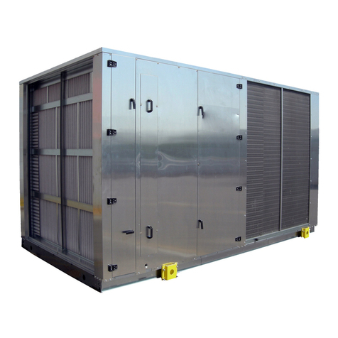
AERMEC NRK 0150 User manual
Other AERMEC Air Conditioner manuals

AERMEC
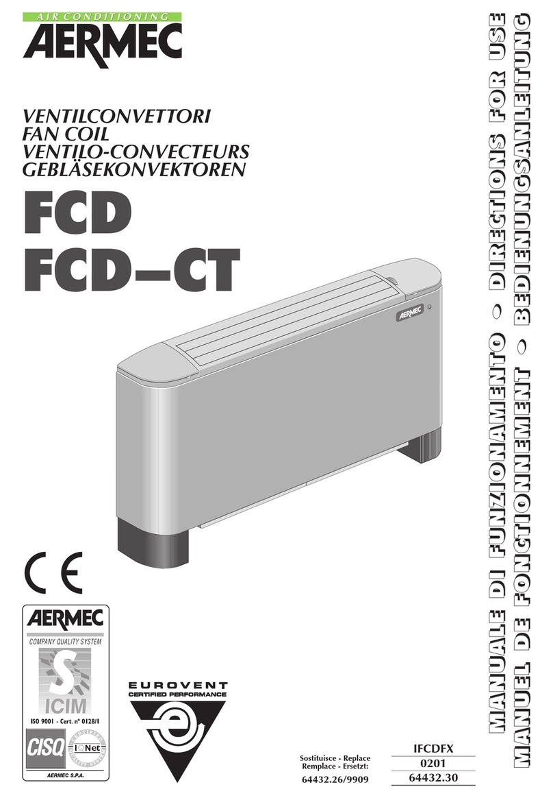
AERMEC FCL Series User manual
AERMEC
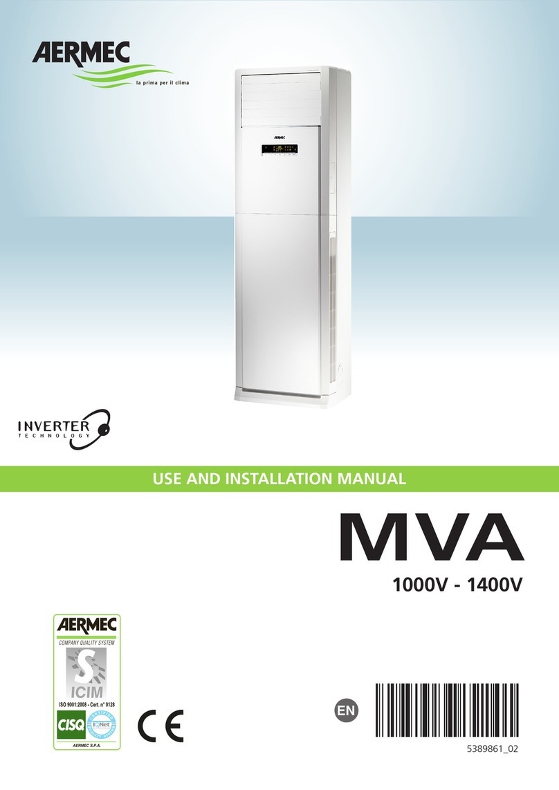
AERMEC FCD Manual
AERMEC
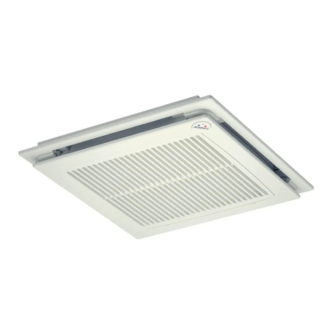
AERMEC MVA Technical specifications
AERMEC
AERMEC GLFI10N User manual
AERMEC
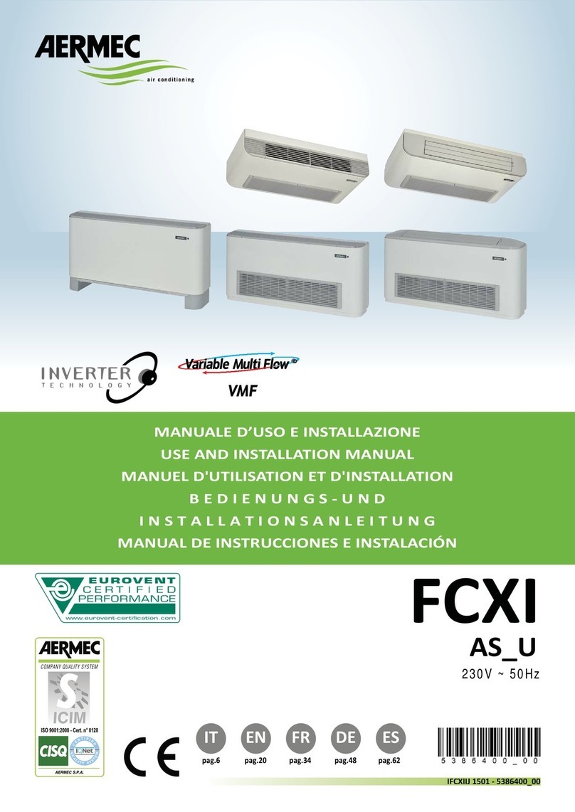
AERMEC FCXI Series Technical specifications
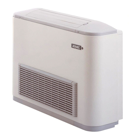
AERMEC
AERMEC FCX Series Technical specifications
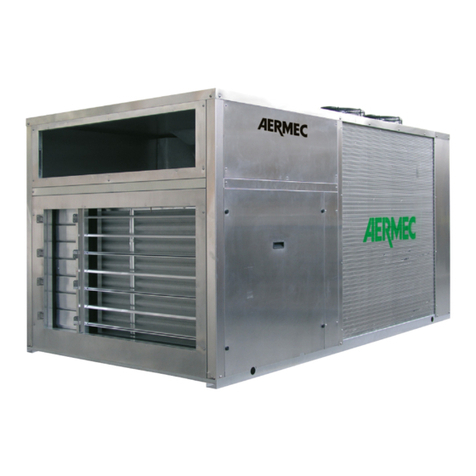
AERMEC
AERMEC RTE Series Manual

AERMEC
AERMEC FCX-P Series User manual
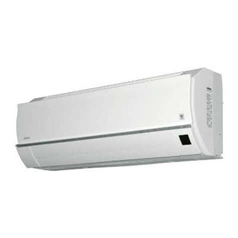
AERMEC
AERMEC MIH Manual
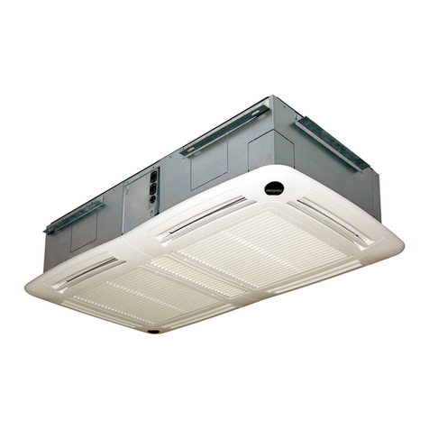
AERMEC
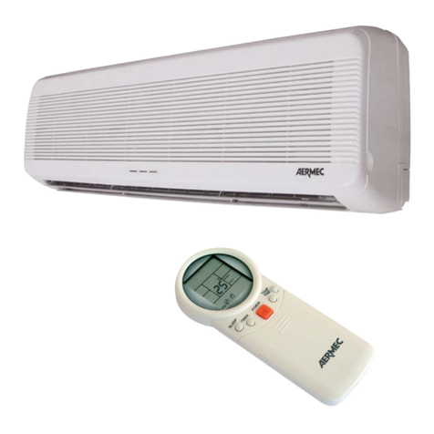
AERMEC FCA Series Installation and operation manual
AERMEC
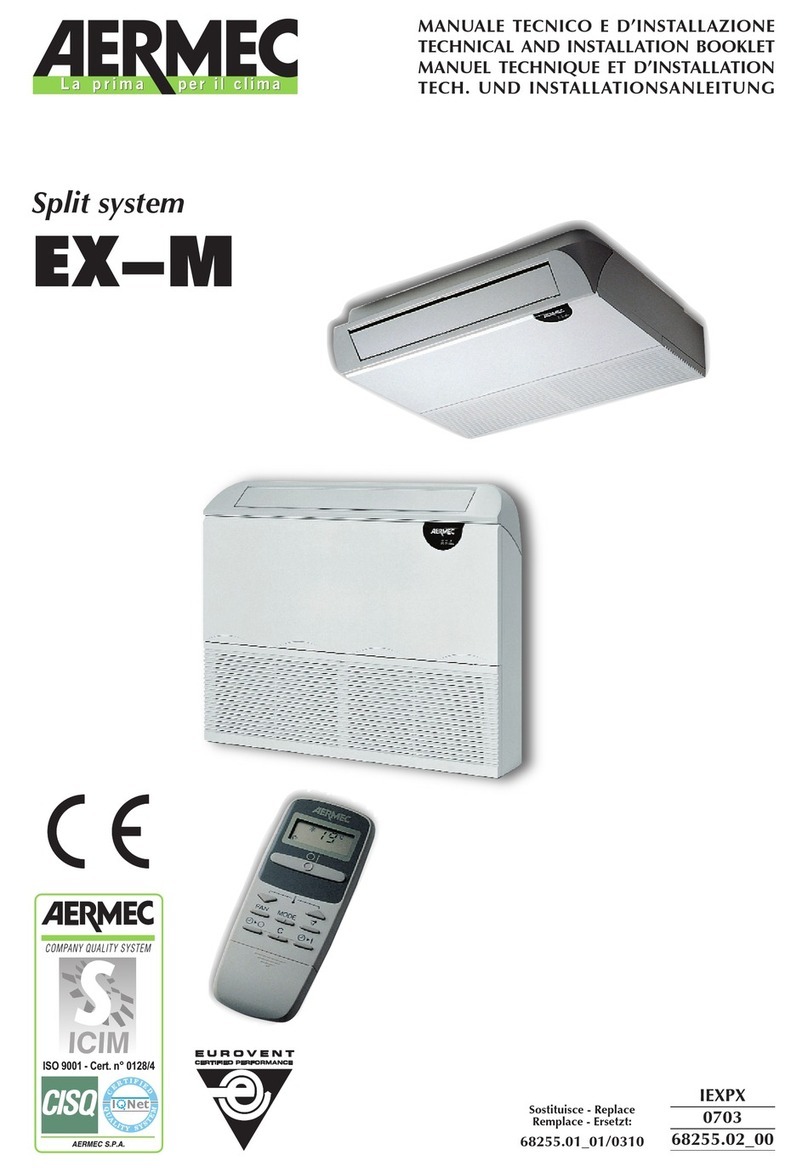
AERMEC EX 070 M Installation and operation manual
AERMEC
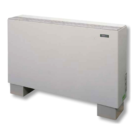
AERMEC FW-R Series User manual
AERMEC
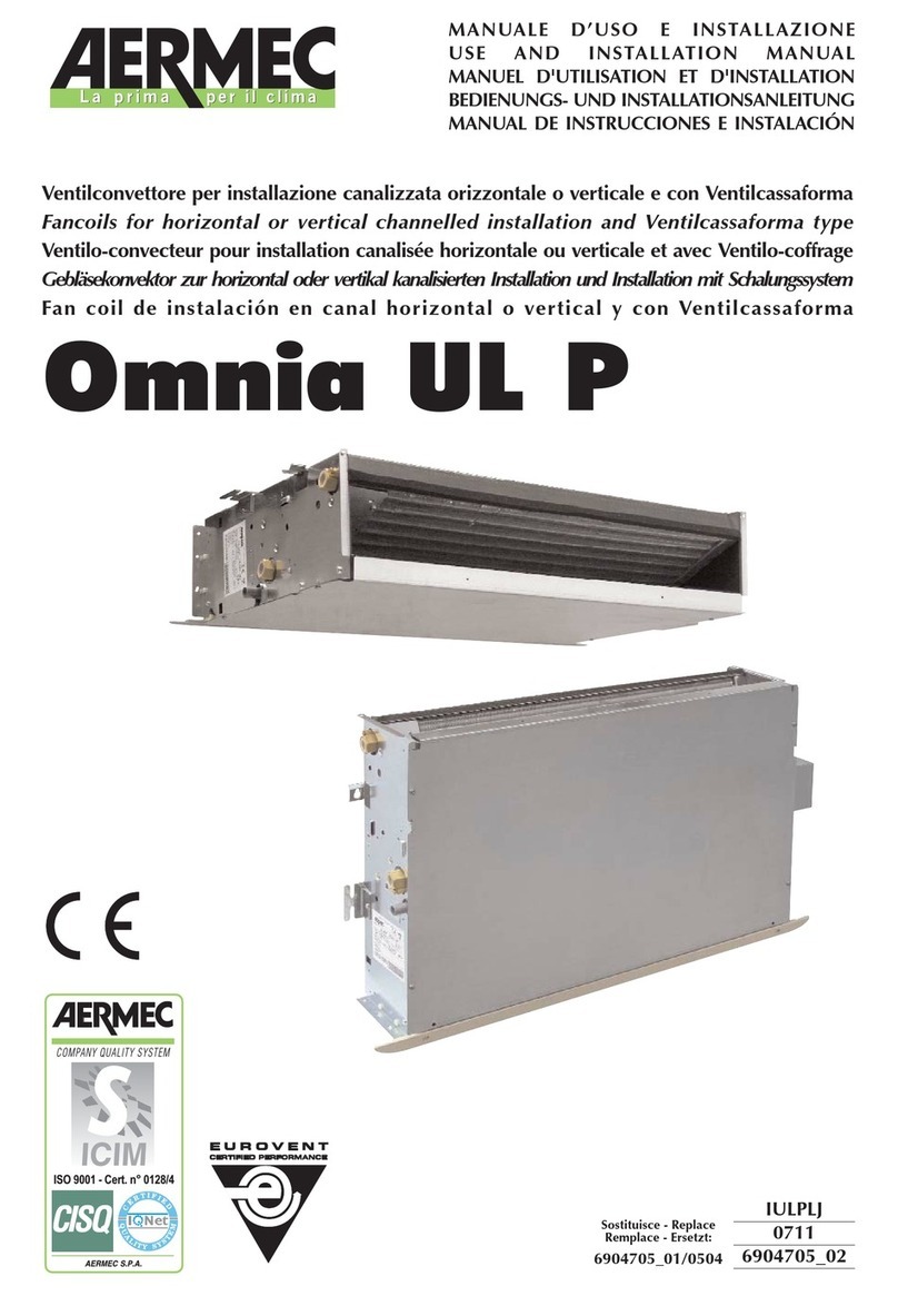
AERMEC Omnia UL P Technical specifications
AERMEC
AERMEC FCW 20 Manual

AERMEC
AERMEC SGE250W User manual

AERMEC
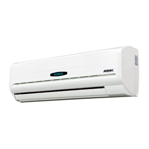
AERMEC FCW 20 Installation and operation manual
AERMEC
AERMEC CWX250W User manual
AERMEC
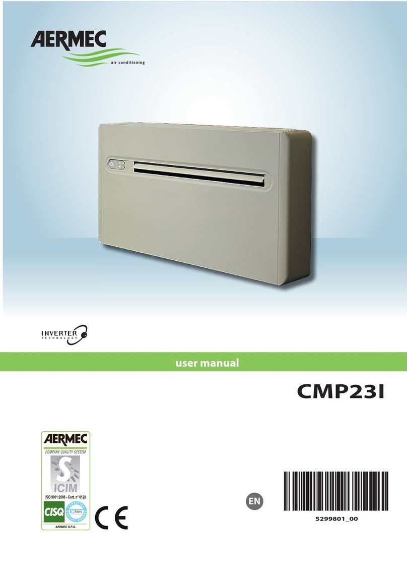
AERMEC XCI-MDIH Series Manual
AERMEC
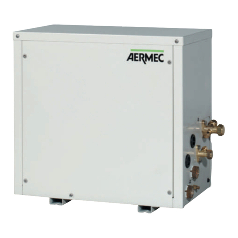
AERMEC CMP23I User manual
AERMEC
AERMEC CWX Series User manual
Popular Air Conditioner manuals by other brands

CIAT
CIAT Magister 2 Series Installation, Operation, Commissioning, Maintenance

Bestron
Bestron AAC6000 instruction manual

Frigidaire
Frigidaire FFRE0533S1E0 Use & care guide

Samsung
Samsung AS09HM3N user manual

Frigidaire
Frigidaire CRA073PU11 use & care

Soleus Air
Soleus Air GB-PAC-08E4 operating instructions

McQuay
McQuay MCK020A Technical manual

Webasto
Webasto Frigo Top 25 DS Instructions for use

Frigidaire
Frigidaire FAZ12ES2A installation instructions

Mitsubishi Electric
Mitsubishi Electric MSC-GE20VB operating instructions

Mitsubishi Electric
Mitsubishi Electric PLA-M100EA installation manual

Daikin
Daikin Split Sensira R32 Service manual
