Aero-motive 1100M Series User manual

SM321009D Page 1 of 9 ©Aero-Motive Nov-03
1100M, 1200M, 1300M, 1400M
& 1500M Series Cable Reel
Service Manual
Aero-Motive Company
A Woodhead Industries, Inc. Subsidiary
Important Safety Instructions
Please read this manual carefully and follow its instructions. Improper use or failure to follow these instructions could
result in serious injury, death or property damage. Operators should be instructed in the safe and proper use and
maintenance of this product. Keep this manual for future reference.
The following safety precautions call attention to potentially dangerous conditions.
DANGER: Immediate hazards which WILL result in severe personal injury or death.
WARNING: Hazards or unsafe practices which COULD result in severe personal injury or death.
CAUTION: Hazards or unsafe practices which MAY result in minor personal injury or product or
property damage.
INSTALLATION
WARNING:
Lock out all electrical power and remove all spring tension from the reel before opening
any enclosure or performing any service to this reel. Make sure all circuits carry
appropriate fuse protection. Hazards or unsafe practices COULD result in severe personal
injury or death.
WARNING: Failure to read, understand, and follow these instructions creates hazards that COULD
result in personal injury or death.
CAUTION:
Instruct operators in the safe, proper use, and maintenance of the reel. Keep this manual
for future reference. Hazards or unsafe practices MAY result in minor personal injury or
product or property damage.
MOUNTING
The fixed base of the reel allows mounting in several different positions
including base up, base down, or wall mounted. Here are general mounting
requirements:
•Main-shaft must be horizontal.
•Centerline of the spool assembly must be on line with the cable run.
•When mounted overhead in base up position, add a secondary chain,
bracket or other safety device to prevent reel from falling in case the
mounting bolts are removed or become loosened from vibration.
SECONDARY SUPPORT CHAIN
DANGER: A secondary safety cable or chain is to be attached to all reels mounted overhead to prevent
reel from falling. Immediate hazards WILL result in severe personal injury or death.
All reels mounted over head should have a secondary support chain to protect personnel in case of
structure or mounting component failure. Attach one end of secondary support chain or cable to
secondary support point on reel. Attach other end of secondary support chain or cable to a support
component other than that which supports the reel. The chain or cable should be as short as possible
allowing reel to drop no more than 6 to 12 inches if the primary connection is released. A secondary
support is offered as an accessory item.

SM321009D Page 2 of 9 ©Aero-Motive Nov-03
PIVOT/SWIVEL BASE
If optional pivot /swivel base is used, reel will be self-aligning to direction of cable run. A four roller cable
guide, the 2FMYE or 3FMYE must be used with pivot or swivel mounts.
WIRING SUPPLY CONNECTION
NOTE: See “Service, Working Cable Replacement/Installation” if cable needs to be installed.
Input power connection is made to junction box, if supplied, or through a
connector or coupling which is inserted into the 1” x 11 1/2” N.P.S.C. main
shaft pipe thread. If junction box not supplied then wire directly to the slip
ring. See figure for connectors to be used at different amperages. Check
continuity on each conductor, and replace junction box cover.
GUIDE RAIL, ROLLER GUIDE, AND SHEAVES
Guide Rails – come standard with all reels. If
recovery application with middle cable attachment
and two-way payout, guide rails allow full freedom
from side to side. There must not be a tendency for
cable to pull to either side. Realign reel with payout
and guide rails with reel flanges if needed.
Roller Guide - used when cable is pulled out in a
line tangent to drum surface. Adjust guide to
minimize cable deflection to cable travel. This type
of guide is needed for manual pull out applications
using ratchet lock option. If not manual pull out, reel
is often best operated without a guide. Standard
guide rails assure cable will not over spool.
Sheaves are used to bend cable around corners.
Typical minimum bend radius of the sheave should
be about 7.5 x cable diameter. Requirements can
vary depending on cable manufacturer
specifications. Sheaves should have flat surfaces for
cable to ride on. The movement of cable through a
sheave should be in the same plane as the cable
spool. Changing planes can greatly reduce cable
life.
CABLE WINDING
There are many types of cable that may be installed on your cable reel depending on application. Select
the cable most appropriate for your application requirements. Many cables come from the factory with a
wax-like film that can encourage uneven wrapping. At initial set up it is common to use a dry lubricant
(talc powder), or silicone based grease to encourage more even winding. Also critical to proper winding is
the proper setting of “Setup Turns”. See appropriate section. In some cases sheaves and unanticipated
application features can require more tension than offered with standard reels. Contact factory for
application assistance.

SM321009D Page 3 of 9 ©Aero-Motive Nov-03
OPERATION
RATCHET
When specified, reels are equipped with a ratchet lock. Tension of the
motor spring holds reel against ratchet. A sharp tug on cable releases
ratchet permitting reel to retract cable. Each ratchet dog is supplied
with counter-weight fastened by single screw. Ratchet position and the use
of the counter-weight depend upon the installed position of the reel. Here
are requirements for ratchet usage:
•Wall mounting: Reel must be mounted with the ratchet side of the frame
down with counter-weight attached.
•Base down mounting: Use the ratchet counter-weight.
•Base up mounting: Remove the counter-weight.
SPRING TENSION
Reels are not pretensioned. To prepare reel for use, you must apply pretensioning turns to spool
assembly before connecting free end of working cable. The number of required setup turns can vary
considerably depending on application and on desired cable tension force. Set spring tension by turning
fully wrapped reel through a specific number of turns. See following guidelines on setup turns.
SET-UP TURNS
CAUTION: Failure to test for adequate spring revolutions can cause spring damage. Hazards or
unsafe practices MAY result in minor personal injury or product or property damage.
Spring driven cable reels must always have setup turns applied before installing the cable free end.
A minimum of 2 set up turns are to be applied per spring in the reel. See chart on next page for
minimum setup turn recommendation for your cable reel.
Example: 1475-16-320 cable reel requires 10 minimum setup turns
Reel Prefix xxxx-05-xxx xxxx-17-xxx xxxx-10-xxx xxxx-16-xxx
11x2 Setup-4 / Tot-20 Setup-4 /Tot-18 Setup-4 / Tot-28 Setup-4 / Tot-24
11x3 6 / 30 6 / 27 6 / 42 6 / 36
11x4 8 / 40 8 / 36 8 / 56 8 / 42
11x5 10 / 50 10/ 45 10 / 70 10 / 54
12x3 6 / 30 6 / 27 6 / 42 6 / 36
12x5 10 / 50 10/ 45 10 / 70 10 / 54
14x3 6 / 30 6 / 27 6 / 42 6 / 36
14x5 10 / 50 10/ 45 10 / 70 10 / 54
14x6 12 / 60 12 / 54 12 / 84 12 / 72
13x4 4 / 20 4 / 18 4 / 28 4 / 24
13x6 6 / 30 6 / 27 6 / 42 6 / 36
15x4 4 / 20 4 / 18 4 / 28 4 / 24
15x6 6 / 30 6 / 27 6 / 42 6 / 36

SM321009D Page 4 of 9 ©Aero-Motive Nov-03
In some instances more setup turns can be added to improve reel performance.
Use following equation to find maximum allowed setup turns.
Active Turns-number of spool turns to unwrap active cable (pull off cable and count turns.)
Total Turns-see chart above
Setup -see chart above
Maximum Setup = Total Turns - (½ x Setup) - Active Turns
Example: 1475-16-320 cable reel using 33 Active Turns to wind cable
54 – (½ x 10) – 33 = 16 maximum allowed setup
SERVICE
WARNING:
Always disconnect electrical power before dismantling any part of the reel. Fuse size must
not be greater than maximum amperage capacity of cable. Remove all spring tension
before attempting any service. Hazards or unsafe practices COULD result in severe
personal injury or death.
INSTALL/REPLACE WORKING CABLE (Both new installations and for replacement of working cable.)
NOTE: Add about 10 ft. extra to active cable length (3 ft. for a dead wrap on spool and 7 ft. for slip ring
connections). Also add required length for your connection at cable fixed end.
Remove slip ring cover, cable clamp from spool assembly and cable connector. Determine length to strip
outer-jacket of cable by inserting it through gooseneck fitting until reaching most distant brush terminal.
Mark outer-jacket at location inside connector. Remove cable, and strip outer-jacket six inches above
mark to ensure adequate conductor length to connect to brush terminals. Pull stripped end of cable
through slot in spool assembly flange adjacent to cable clamp. Insert cable through cable connector until
outer-jacket becomes visible in fitting. Feed conductors though entrance ring into the collector assembly
to reach their proper brush terminals. Tighten watertight cable connector. Secure individual conductors to
proper brush terminals. Install cable clamp making sure cable is not kinked or pinched. Load working
cable onto spool assembly by manually winding the reel. Count the number of turns required to fully load
cable; you can use this to determine maximum setup turns.
NOTE: While winding, observe cable-wrapping pattern and make sure that all twists and kinks are
removed from the cable. Cable twists can cause an erratic wrapping pattern and shorten cable
life. See “Cable Winding” section on page 2.
Wrapping of cable will produce a clinking sound as the springs disengage from the drive hubs. This is a
protective feature to prevent damage to springs. All springs will re-engage when spool is wound in
opposite direction. Terminate the free end of working cable only after setup turns are applied.
COLLECTOR RING REPLACEMENT
WARNING: Disconnect and lock out all power to reel before servicing collector ring assembly.
Hazards or unsafe practices COULD result in severe personal injury or death.
CAUTION: Check continuity and replace all covers before turning on electrical power. Hazards or
unsafe practices MAY result in minor personal injury or product or property damage.
Remove collector ring cover. Disconnect working cable lead wires from terminals of brush holder.
Disconnect main shaft lead wires and remove assembly by loosening set screws and sliding collector ring
off the main shaft. To reassemble, reverse the above procedure, making sure each brush is properly
centered on its corresponding ring with full contact. The collector ring assembly should be snug against
the entrance ring assembly.

SM321009D Page 5 of 9 ©Aero-Motive Nov-03
MAIN SPRING REPLACEMENT
WARNING:
To prevent personal injury, death or property damage,
hold center of spring down as the hub is pulled out. If the
center is allowed to rise up, the spring may escape from
its container. Hazards or unsafe practices COULD result
in severe personal injury or death. DO NOT remove the
spring from its container.
WARNING:
To prevent personal injury, death or property damage, handle all springs with care. Use
suitable protective gloves for spring handling. Hazards or unsafe practices COULD result
in severe personal injury or death.
NOTE: It is recommended to replace all springs since unbroken springs of same age will likely need
replacement very soon as well. Failure to do this will result in much more frequent maintenance.
It is advisable to wear gloves or other suitable hand protection since sharp edges may be encountered
when handling springs. Follow same instructions as for collector ring replacement above. Remove four
hex head cap screws on the goose neck fitting, then remove from entrance ring. Remove six bolts on
entrance ring and pull off main shaft along with driving ring and spacer. Remove spool so spring and cup
assemblies are exposed.
Each spring assembly can now be removed in their cup shaped containers. Lift each spring off main shaft
being careful to disengage the hub first by rotating it in the tension reducing direction until a click is heard
and hub is unhooked. Grab under each edge with your hands to help hold the spring in the pocket while
lifting off and until it is safely right side up on bench. If spring is pulling out of pocket stop process and
attempt to disengage.
The parallel spring 1300 and 1500 series units come with interlocking parallel spring pockets and with
doublewide hubs. If the hub starts coming off with the top spring do not be alarmed. Just make sure it
doesn’t pull the spring out of pocket.
When disposing of old or broken spring assemblies, coils should
be welded or wired together to prevent possible injury to scrap
handling personnel. Replace broken spring assembly, and
reassemble the springs in reverse order. When replacing spring
assemblies make sure that the square projection, on the end of
the spring hub below, is properly engaged in the opening of
adjacent spring cup.Refer to parts drawing for part sequence and
location.
LUBRICATION
Springs and bearings have been sufficiently lubricated at the factory to last for the normal life of
the motor. If grease has been removed during maintenance it should be replaced with good quality high-
low, temperature grease (Texaco AFB 2 or equal). Bearings should be packed, and springs should have
enough grease in the cup to thoroughly coat the entire spring as it works in during use.

SM321009D Page 6 of 9 ©Aero-Motive Nov-03
REPLACEMENT PARTS

SM321009D Page 7 of 9 ©Aero-Motive Nov-03
Reference
Number *
Part
Number Qty. Description
1 H82240045
H82240046
H82240047
H82240048
A/R
A/R
A/R
A/R
Cover; Junction Box (1” NPT)
Cover; Junction Box (1-¼ ” NPT)
Cover; Junction Box (1-½ ” NPT)
Cover; Junction Box (2” NPT)
5 6079300000
6079400000
2
2
Tie Bar- 3rd Digit = (4, 6, 5) (1x4x,1x6x,1x5x)
Tie Bar (1x7x)
9 C13490015 2 Bolt; Carriage M8x45
10 C22180118 2 Nut; Hex Head Mx1.25
11 C01190118 2 Washer; Spring Lock M8
12 1R
2R
3R
4928500003
1
1
1
Assembly; Guide Rail Digits 1-4 = (11XX)
Assembly; Guide Rail (12XX,13XX)
Assembly; Guide Rail (144X,154X)
Assembly; Guide Rail (147X,157X)
13 C11080564 8 Screw; Hex Head Cap M6x25
14 C01070558 4 Washer; Flat SAE M6
15 2FMYE
3FMYE
2FMYE7
3FMYE7
A/R
A/R
A/R
A/R
Assembly; Cable Guide (2-FM)
Assembly; Cable Guide (3-FM)
Assembly; Cable Guide (2-FMYE7 (IF 3RD DIGIT =7)
Assembly; Cable Guide (3-FMYE7 (IF 3RD DIGIT =7)
18 4290400002
4290400003
4290400004
4290400005
4290400006
4062100005
4062100007
4062100010
4062100011
4078300405
4078300407
4078300408
4078300707
4078300708
4078300012
1
1
1
1
1
1
1
1
1
1
1
1
1
1
1
Standard or Reverse Rotation Spools No Ratchet Lock
Assembly; Spool Digits 1-4 = (1142) lock
Assembly Spool (xx43)
Assembly Spool (xx63)
Assembly Spool (xx64)
Assembly Spool (xx65)
Assembly Spool (xx53)
Assembly Spool (xx55)
Assembly; Spool (xx54)
Assembly Spool (xx56)
Assembly; Spool (xx43)
Assembly Spool (xx45)
Assembly Spool (xx46, xx46)
Assembly Spool (xx75)
Assembly Spool (xx76, xx76)
Assembly Spool (xx74)
18 4290400008
4290400009
4290400010
4290400011
4290400012
4062100001
4062100002
4078300001
1
1
1
1
1
1
1
1
Standard Rotation Spools For Ratchet Lock
Assembly; Spool Digits 1-4 = (1142)
Assembly Spool (1143)
Assembly Spool (1163)
Assembly Spool (1164)
Assembly Spool (1165)
Assembly Spool (1253)
Assembly Spool (1255)
Assembly; Spool (1443)

SM321009D Page 8 of 9 ©Aero-Motive Nov-03
4078300002
4078300003
4078300004
4078300005
1
1
1
1
Assembly Spool (1445)
Assembly Spool (1446)
Assembly Spool (1475)
Assembly Spool (1476)
19 H16120036
H16120037
H16120038
H16120039
H16120040
H16120041
1
1
1
1
1
1
Assembly; Clamp (.312-.499 OD)
Assembly; Clamp (.500-.624 OD)
Assembly; Clamp (.625-.749 OD)
Assembly; Clamp (.750-.984 OD)
Assembly; Clamp (.875-1.124 OD)
Assembly; Clamp (1.125-1.188 OD)
20
4378200105
4378200110
4378200116
4378200117
4378200205
4378200210
4378200216
4378200217
*
*
*
*
*
*
*
*
Springs for Digits 1& 2 = (11,12,14) *= 4th digit
Assembly; Spring and Cup Digit 5 & 6 = (05) (Standard Rotation)
Assembly; Spring and Cup ( 10)
Assembly; Spring and Cup ( 16)
Assembly; Spring and Cup ( 17)
Assembly; Spring and Cup Digit 5 & 6 = (05) (Reverse Rotation)
Assembly; Spring and Cup ( 10)
Assembly; Spring and Cup ( 16)
Assembly; Spring and Cup ( 17)
20b
H41220080
H41220082
H41220084
H41220086
H41220081
H41220083
H41220085
H41220087
*/2
*/2
*/2
*/2
*/2
*/2
*/2
*/2
Springs for Digit 1 & 2 = (13, 15) * = 4th digit Pocket End: Square
Assembly; Spring and Cup Digit 5 & 6 = (05) (Standard Rotation)
Assembly; Spring and Cup ( 10)
Assembly; Spring and Cup ( 16)
Assembly; Spring and Cup ( 17)
Assembly; Spring and Cup Digit 5 & 6 = (05) (Reverse Rotation)
Assembly; Spring and Cup ( 10)
Assembly; Spring and Cup ( 16)
Assembly; Spring and Cup ( 17)
20c
H41220088
H41220090
H41220092
H41220094
H41220089
H41220091
H41220093
H41220095
*/2
*/2
*/2
*/2
*/2
*/2
*/2
*/2
Springs for Digit 1 & 2 = (13, 15) * = 4th digit Pocket End: Round
Assembly; Spring and Cup Digit 5 & 6 = (05) (Standard Rotation)
Assembly; Spring and Cup ( 10)
Assembly; Spring and Cup ( 16)
Assembly; Spring and Cup ( 17)
Assembly; Spring and Cup Digit 5 & 6 = (05) (Reverse Rotation)
Assembly; Spring and Cup ( 10)
Assembly; Spring and Cup ( 16)
Assembly; Spring and Cup ( 17)
21 4017600000 4 Ring; Driving
22 00230P0122 A/R Pin; Driving (.156 DIA. x .625)
24 11LM
12LM
14LM
A/R
A/R
A/R
Assembly; Ratchet (optional) (1100M)
Assembly; Ratchet (optional) (1200M, 1300M)
Assembly; Ratchet (optional) (1400M, 1500M)
26 5974400001
5974400002
H41650003
H41650004
A/R
A/R
A/R
A/R
Assembly; Rotating Spring Hub (11XX, 12XX, 14XX standard rotation)
Assembly; Rotating Spring Hub (11XX, 12XX, 14XX reverse rotation)
Assembly; Rotation Spring Hub (13XX, 15XX standard rotation)
Assembly; Rotation Spring Hub (13XX, 15XX reverse rotation)
27 M76420020
M76470008
M76420021
M76420022
1
1
1
1
Hub; Fixed Spring (11XX, 12XX, 14XX standard rotation)
Hub; Fixed Spring (11XX, 12XX,14XX inch fixed, reverse rotation)
Hub; Fixed Spring (13XX, 15XX standard rotation)
Hub; Fixed Spring (13XX, 15XX reverse rotation)
28 4077300002 2 Key; Square
29 4000500000 2 Bearing
30 M65140092 1 Plate; Cable Drum End
31 4291900000 1 Combination Spacer and Bearing Seal
32 4292000000 1 Seal; Bearing
33 M26740127 1 Screw; Hex Head M12x1.25
34 40149-xxxx A/R Shaft; Main ( supply model number for identification, or if you have 7th Digit = 3 or 4
measure length of shaft in inches, xxx= length in inches)

SM321009D Page 9 of 9 ©Aero-Motive Nov-03
35 H22110388
H22110390
H22110391
1
1
1
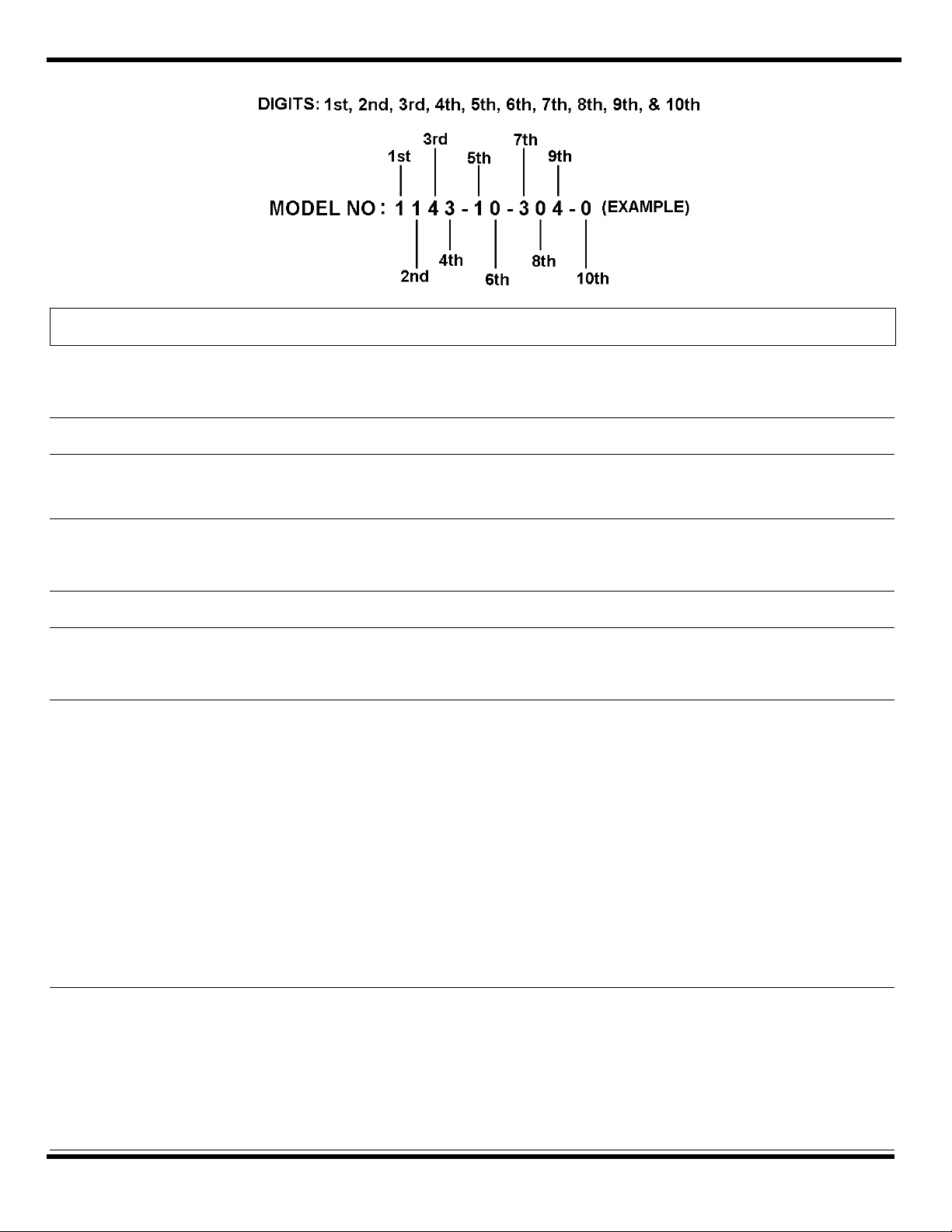
Stand; Weldment (Digit 1 & 2 = 11)
Stand; Weldment (12, 13)
Stand; Weldment (14, 15)
36 C01190116 17 Washer; Spring Lock M6
37 C22180116 4 Nut; hex M6
38 01151P0019
01151P0020
01151P0014
01151P0015
01151P0016
01151P0024
01151P0025
A/R
A/R
A/R
A/R
A/R
A/R
A/R
Connector; Cable (.375-.499 OD)
Connector; Cable (.500-.624 OD)
Connector; Cable (.625-.750 OD)
Connector; Cable (.751-.880 OD)
Connector; Cable (.930-1.065 OD)
Connector; Cable (.1.066-1.187 OD)
Connector; Cable (.1.188-1.625 OD)
39 00669P0045 A/R Bushing 2-1-¼
40 5491000001
5491000002
1
1
Fitting; Goose Neck (.375-.929 OD)
Fitting ; Goose Neck (.930-1.625 OD)
41 C71180001 1 Cover; Conduit
42 C22180210 1 Nut; Hex Head Jam (M10x1.5)
43 M25060011 1 Stud; Drive
45 C01190115 A/R Washer; Lock M5
46 M14210027 1 Gasket
47 H82630032
H82630033
H82630034
H82630035
H82630036
H82630037
H82630039
H82630040
1
1
1
1
1
1
1
1
Cover; Collector Ring 3.25” length (For digits 7,8,9 = 303, 304)
Cover; Collector Ring 5.25” length ( = 308, 402, 403, 404)
Cover; Collector Ring 7.25” length ( = 312, 405, 406, 902, 903)
Cover; Collector Ring 9.25” length ( = 314, 316, 407, 408, 409, 904, 905)
Cover; Collector Ring 11.25” length ( = 318, 320, 410, 411)
Cover; Collector Ring 13.25” length ( = 324, 906)
Cover; Collector Ring 15.25” length ( = 328, 330)
Cover; Collector Ring 17.25” length ( = 336)
48 C11080531 1 Screw; Hex Head Cap (GROUND) M5x10
49 00903P0001
00904P0001
4027900002
A/R
A/R
A/R
Cap, 7th Digit = (3)
Insulator 7th Digit = (3)
Connector; Wire 7th Digit = (4)
50 SRXXX
AGXXX
1 Assembly; Collector Ring (Digits 7,8,9 = XXX).
If Silver Slip Ring, 10th digit = S, then use this model.
51 00580P0137 1 Ring ;Retaining (1.500)
52 5629100000 1 Ring; Thrust
53 M53800005 3 Clamp; Cover
54 M26740141
M26740142
M26740143
M26740134
M26740137
M26740132
6
6
6
6
6
6
Tie Bolt, cable drum Digits 1-4 = (1165,1255,1445)
Tie Bolt, cable drum (1356, 1446, 1476, 1546, 1576)
Tie Bolt, cable drum (1257)
Tie Bolt, cable drum (1143, 1163, 1443, 1253)
Tie Bolt, cable drum (1164)
Tie Bolt, cable drum ( 1142)
55 M64560017 1 Ring; Entrance
57 5491200000 1 Gasket
63 00580P0030 AR Ring; Retaining (for .375 shaft) (1200M, 1400M)
64 6110500000 2 Spacer
KIT H25460024 AR Entrance Ring Kit (Includes 55, 53, 22 & 13)
Aero-Motive Company AKAPP Electro Industrie Woodhead Connectivity LTD. Woodhead Asia PTE LTD. Woodhead Canada LTD.
WA Woodhead Industries Inc. Subsidiary WA Woodhead Industries Inc. Subsidiary WA Woodhead Industries Inc. Subsidiary WA Woodhead Industries Inc. Subsidiary WA Woodhead Industries Inc. Subsidiary
PO Box 2678
Kalamazoo, MI 49003-2678
(616) 337 7700
(800) 999 8559
FAX: (800) 333 6119
www.aeromotive.com
Nijverheidsweg 14 Box 54
NL-3771 ME Barneveld
NL-3771 AB Barneveld
Holland
(31) 34 241 4022
FAX: (31) 34 249 2384
www.akapp.com
Factory No. 9
Rassau Industrial Estate
Ebbw Vale Gwent NP3 5SD
United Kingdom
(0495) 35 0436
FAX: (0495) 35 0877
401 Commonwealth Drive #04-04
Haw Par Technocentre
Singapore 0314
(65) 261 6533
FAX: (65) 479 3588
1090 Brevik Place
Mississauga Ontario
L4W 3Y5 Canada
(905) 624-6518
FAX: (905) 624-9151
www.woodhead.ca
This manual suits for next models
4
Table of contents
Other Aero-motive Tools manuals
Popular Tools manuals by other brands

ISL Animal Health
ISL Animal Health Injector Series Instruction leaflet

XPOtool
XPOtool 62797 Operation manual

Forza
Forza 1300 CTH Series user manual

TE Connectivity
TE Connectivity 58024-1 instruction sheet

WOHLHAUPTER
WOHLHAUPTER 310 Series operating instructions

Howmet Aerospace
Howmet Aerospace 2057 Series instruction manual