manuals.online logo
Brands
  1. Home
  2. •
  3. Brands
  4. •
  5. Woodhaven
  6. •
  7. Tools
  8. •
  9. Woodhaven EZ Lift 1429 User manual

Woodhaven EZ Lift 1429 User manual

1429 & 1430
EZ Lift
Owners Manual
U.S. Patent #6,742,558
Please read carefully!
Tools needed for assembly:
Phillips screwdriver
Tools needed for use:
9/16" socket & wrench
Identify and verify that you have all the parts listed. Read through
the instructions once completely before proceeding.
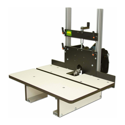
The EZ Lift is designed for tables with a 9-1/4" x 11-3/4" plate
opening. It is guaranteed square to within 1/4º and has 1.7" of fine
adjustment, plus the coarse adjustment from your router motor. If you
feel any of these specs do not meet your needs, please return the EZ Lift
to your place of purchase before assembling or using it.
The 1429 EZ Lift will accept a 3-1/2" dia. motor (PC 690 & 892,
Bosch 1617 & DeWalt 616/618). The 1430 EZ Lift will accept a Porter
Cable 7518 router motor, but an adapter is available to accept smaller
diameter routers from Porter Cable, Bosch & DeWalt (PN 1425R1). A
shim (PN 1430S) is available for the Milwaukee 5625.
ASSEMBLY
Step 1: Assemble the pair of Vertical Supports (1430CX) using two 1/2"
barrel nuts (5793B) and two 1/4-20 x 1" screws (MF015). Make sure
they are assembled on a flat surface like a table saw table and that the
vertical face/edge of the assembly is flush. Tighten the screws securely.
See fig 1.
Adjust the two Slides (one on each Vertical Support) up or down
until the countersunk holes in the Slide are visible through the holes in
the Vertical Supports. NEVER attempt to adjust the bolts holding the
Slides on the Vertical Supports. This is done at the factory and needs no
further adjustment. See fig. 2.
Step 2: Attach the Router Block Handle (5860-5) to the Router Block.
Install the 3/8" spacer (PS004) on the threaded rod of the Router Block
Handle. Insert a 1-1/8" barrel nut (5791B) in the location shown on the
Router Block approximately 7/16" in. Make sure the slot in the barrel
nut is in line with the mating cross hole in the Router Block. Start, but
do not tighten, the handle at this time. See fig. 3.
2
Qty Part# Description
10 MF015 1/4-20 x 1" screw
Qty Part# Description
6 5793B 1/4-20 x 1/2" barrel nut
B
C
Qty Part# Description
2 MF040 10-24 x 3/4" screw
F
Qty Part# Description
1 WL001 1/4" lock washer
Qty Part# Description
1 1430F Lift Nut
H
G
Qty Part# Description
1 PS004 3/8" spacer
A
Qty Part# Description
1 MT030 1/4-20 x 1-1/4" screw
E
Qty Part# Description
5 5791B 1/4-20 x 1-1/8" barrel nut
D
Qty Part# Description
1 WB002 1/4" washer
I
Parts List:
Additional parts not
shown in parts drawings -
refer to photos in manual:
Qty PN Description
1pr 1430CX Vertical Supports
1 1430B or 1430B1 Router Block
1 1430P Router Plate
Hardware Package (1430H):
Hdw. items A thru I - shown
1 5860-5 Router Block Handle
1 1430X Adjuster Assembly
Accessory Package (1430I):
1 1430G Dial Indicator
1 140B Blank Insert
1 140E 2" Insert
1 101A Starting Pin
Fig. 1
Fig. 2
1430CX Vertical Supports
being connected
Make sure edge
is flush to face
Adjust Slides on
Vertical Supports
3
Attach the Router Block (1430B or 1430B1) to the Vertical
Support assembly using four 1-1/8" barrel nuts (5791B) and four 1/4-20
x 1" screws (MF015). Lay the Router Block on its side. Insert the bar-
rel nuts in the locations shown on the Router Block approximately 7/16"
in to the block. Make sure the slot in the barrel nut is in line with the
mating cross hole in the Router Block. See fig. 4.
Insert a 1/4-20 x 1" screw through the hole in the Vertical Support,
continuing through the countersunk hole in the Slide and into the Router
Block until it contacts the barrel nut. Loosely tighten the screw in the
barrel nut. Repeat this procedure with the other three holes until the
Router Block is loosely attached. Next lightly tighten the four screws.
Now tighten the four screws fully.
With the assembly upright, push down on the Router Block until it
slides all the way down to the bottom of it's travel on the Vertical
Supports. See fig. 5.
Step 3: Insert the Lift Nut (1430F), large threaded hole first, into the
rectangular opening in the Router Block. See fig. 6.
Install a 1/4" lock washer (WL001) and a 1/4" washer (WB002) on
to the 1/4-20 x 1-1/4" screw (MT030). Install the screw through the hole
in the Router Block where indicated and loosely tighten it in the Lift
Nut. See fig. 5 & 7.
Install the Adjuster Assembly (1430X) in the Lift Nut. From the
router plate side of the Router Block, insert the bolt into the Router
Block until it contacts the Lift Nut. Screw the bolt into the Lift Nut until
the mounting plate of the Adjuster Assembly is slightly above the edges
of the Vertical Supports. See fig. 8.
Fig. 3
Fig. 4
Fig. 5
Fig. 6
Fig. 7
Fig. 8
Install Router Block
Handle in Router Block
Attach Router Block
to Slides
5791B
Push Router Block to
bottom of travel
Install Lift Nut
Fasten Lift Nut to Router Block
Mounting Plate of
Adjuster Assembly
Vertical Supports
Router Plate side
of Router Block
Screw Adjuster
Assembly in Router
Block/Lift Nut until
the mounting plate is
slightly above the
Vertical Supports.
4
Step 4: Attach the Router Plate to the Vertical Support/Router Block
assembly. Install four 1/2" barrel nuts (5793B) in the holes indicated in
the two Vertical Supports, aligning the slot in the nut with the cross
slot/hole in the Vertical Support. Position the Router Plate over the
assembly, aligning the mounting holes in the Router Plate with the corre-
sponding holes in the Vertical Supports and the Adjuster Assembly. See
fig. 9.Insert the four 1/4-20 x 1" screws (MF015) through the mounting
holes in the Router Plate, into the barrel nuts and loosely tighten. Align
the two holes in the mounting plate of the Adjuster Assembly with the
corresponding holes in the Router Plate. Insert the two 10-24 x 3/4"
screws (MF040) through the Router Plate, into the mounting plate and
tighten securely. Move the Router Plate so it is as centered as possible
(this does not need to be perfect) on the router and tighten the screws
securely. See fig. 10. Tighten the screw attaching the Lift Nut to the
Router Block. See fig. 7.
NEVER install the router partially in the Router Block! The
router should ALWAYS be flush, or sticking above, the Router Block
when safely installed. See fig. 11.
USING THE LIFT
Press the Dial Indicator onto the socket so that the end of the sock-
et is protruding approximately 1/4" out the bottom of the Dial Indicator.
The Dial Indicator should fit snugly on your socket, but be able to be
turned (for zeroing-out purposes) on the socket by hand. If the Dial
Indicator is too tight, sand one or several of the four protrusions slightly
with 120 grit sandpaper wrapped around a dowel until a snug fit is
achieved.
The hash marks on the edge of the Dial Indicator represent .0078"
(1/128") per 1/8th turn or .0156" (1/64") per 1/4th turn. There is .0625"
(1/16") of adjustment per one revolution. Turn the Dial Indicator on the
socket to align the desired hash mark with the mark in the router plate to
zero it out. See fig. 12.
When adjusting bit height, lower the bit (turn counter-clockwise) at
least 1/4 turn past the level needed (this compensates for any backlash),
then raise it (turn clockwise) to the desired setting. By varying the
router position in the Router Block, it's possible to raise many routers
above the table for bit changing. As with all routing, the best results are
achieved by making several light passes vs. one heavy pass.
Periodically clean the threads of the Adjuster Assembly and Lift
Nut. Check all screws, especially after initial use, to insure they are
tight. If you are having trouble holding a bit height setting, tighten the
four locknuts a small amount. See fig. 9.
©Copyright WOODHAVEN INC. 8/4/04
(800) 344-6657 or WWW.WOODHAVEN.COM
Fig. 12
Fig. 10
Fig. 9
Install barrel nuts
at four locations
Four locknuts
Fig. 11
Not OK! OK
OK

This manual suits for next models

1

Other Woodhaven Tools manuals

Woodhaven 6012 User manual

Woodhaven

Woodhaven 6012 User manual

Woodhaven 7902 User manual

Woodhaven

Woodhaven 7902 User manual

Woodhaven 8628 User manual

Woodhaven

Woodhaven 8628 User manual

Woodhaven 5435 User manual

Woodhaven

Woodhaven 5435 User manual

Woodhaven 5432 User manual

Woodhaven

Woodhaven 5432 User manual

Woodhaven 8715 User manual

Woodhaven

Woodhaven 8715 User manual

Woodhaven Angle-Ease 1470 User manual

Woodhaven

Woodhaven Angle-Ease 1470 User manual

Woodhaven 3000 User manual

Woodhaven

Woodhaven 3000 User manual

Woodhaven 3210 User manual

Woodhaven

Woodhaven 3210 User manual

Woodhaven HD Panel Master 5432 User manual

Woodhaven

Woodhaven HD Panel Master 5432 User manual

Woodhaven 204 User manual

Woodhaven

Woodhaven 204 User manual

Woodhaven 3000 User manual

Woodhaven

Woodhaven 3000 User manual

Woodhaven 8625 User manual

Woodhaven

Woodhaven 8625 User manual

Woodhaven Angle-Ease 1470 User manual

Woodhaven

Woodhaven Angle-Ease 1470 User manual

Woodhaven 8615 User manual

Woodhaven

Woodhaven 8615 User manual

Woodhaven 7500 User manual

Woodhaven

Woodhaven 7500 User manual

Woodhaven 6002 User manual

Woodhaven

Woodhaven 6002 User manual

Woodhaven 8610 User manual

Woodhaven

Woodhaven 8610 User manual

Woodhaven 8395 User manual

Woodhaven

Woodhaven 8395 User manual

Woodhaven Angle Ease 1425 User manual

Woodhaven

Woodhaven Angle Ease 1425 User manual

Popular Tools manuals by other brands

Sealey AK98945 instructions

Sealey

Sealey AK98945 instructions

Clas Ohlson 40-8674 Mounting

Clas Ohlson

Clas Ohlson 40-8674 Mounting

Ryobi JM82K Manuel d'utilisation

Ryobi

Ryobi JM82K Manuel d'utilisation

Martin EVO Operator's manual

Martin

Martin EVO Operator's manual

BGS technic 98253 instruction manual

BGS technic

BGS technic 98253 instruction manual

Parkside PDST 10 B3 instructions

Parkside

Parkside PDST 10 B3 instructions

BGS technic 9690 instruction manual

BGS technic

BGS technic 9690 instruction manual

Hitachi KC18DCL - HXP Li-Ion Hammer Drill 2 Piece... parts list

Hitachi

Hitachi KC18DCL - HXP Li-Ion Hammer Drill 2 Piece... parts list

Gardena Roll-Up 15 Operator's manual

Gardena

Gardena Roll-Up 15 Operator's manual

Mafell ZH 205 Ec Original operating instructions

Mafell

Mafell ZH 205 Ec Original operating instructions

Metabo KHEV 5-40 BL operating instructions

Metabo

Metabo KHEV 5-40 BL operating instructions

AGI GrainMaxx 5300 Series Operator's manual

AGI

AGI GrainMaxx 5300 Series Operator's manual

KaMo MINITABLE MT100 manual

KaMo

KaMo MINITABLE MT100 manual

SUHNER WH 15 Technical document

SUHNER

SUHNER WH 15 Technical document

BGS technic 9739 instruction manual

BGS technic

BGS technic 9739 instruction manual

Melbourne MTC-49421 owner's manual

Melbourne

Melbourne MTC-49421 owner's manual

Clarke IT1500 Operation & maintenance instructions

Clarke

Clarke IT1500 Operation & maintenance instructions

Jet JOIDR68GD Operation manual

Jet

Jet JOIDR68GD Operation manual

manuals.online logo
manuals.online logoBrands
  • About & Mission
  • Contact us
  • Privacy Policy
  • Terms and Conditions

Copyright 2025 Manuals.Online. All Rights Reserved.