AeroComm AC4424 User manual

AC4424
AC4424AC4424
AC4424
2.4 GHz OEM TRANSCEIVERS
2.4 GHz OEM TRANSCEIVERS2.4 GHz OEM TRANSCEIVERS
2.4 GHz OEM TRANSCEIVERS
Specifications Subject to Change
Specifications Subject to ChangeSpecifications Subject to Change
Specifications Subject to Change
User’s Manual
User’s ManualUser’s Manual
User’s Manual
Version 2.1
Version 2.1Version 2.1
Version 2.1
11160 THOMPSON AVENU
11160 THOMPSON AVENU11160 THOMPSON AVENU
11160 THOMPSON AVENUE
EE
E
LENEXA, KS 66219
LENEXA, KS 66219LENEXA, KS 66219
LENEXA, KS 66219
(800) 492
(800) 492(800) 492
(800) 492-
--
-2320
23202320
2320
www.aerocomm.com
www.aerocomm.comwww.aerocomm.com
www.aerocomm.com
wireles
wireleswireles
wireless@aerocomm.com
s@aerocomm.coms@aerocomm.com
s@aerocomm.com

5
55
5/
//
/8/2007
8/20078/2007
8/2007
2
22
2
DOCUMENT INFORMATION
DOCUMENT INFORMATIONDOCUMENT INFORMATION
DOCUMENT INFORMATION
Limited Warranty, Disclaimer, Limitation of Liability
Limited Warranty, Disclaimer, Limitation of LiabilityLimited Warranty, Disclaimer, Limitation of Liability
Limited Warranty, Disclaimer, Limitation of Liability
For a period of one (1) year from the date of purchase by the OEM customer,
AeroComm warrants the OEM transceiver against defects in materials and workmanship.
AeroComm will not honor this warranty (and this warranty will be automatically void) if
there has been any (1) tampering, signs of tampering; 2) repair or attempt to repair by
anyone other than an AeroComm authorized technician.
This warranty does not cover and AeroComm will not be liable for, any damage or failure
caused by misuse, abuse, acts of God, accidents, electrical irregularity, or other causes
beyond AeroComm’s control, or claim by other than the original purchaser.
In no event shall AeroComm be responsible or liable for any damages arising: From the
use of product; From the loss of use, revenue or profit of the product; or As a result of
any event, circumstance, action, or abuse beyond the control of AeroComm, whether
such damages be direct, indirect, consequential, special or otherwise and whether such
damages are incurred by the person to whom this warranty extends or third party.
If, after inspection, AeroComm determines that there is a defect, AeroComm will repair
or replace the OEM transceiver at their discretion. If the product is replaced, it may be a
new or refurbished product.
Copyright
CopyrightCopyright
Copyright
Information
InformationInformation
Information
Copyright © 2007 AEROCOMM, Inc. All rights reserved.
The information contained in this manual and the accompanying
software programs are copyrighted and all rights are reserved by
AEROCOMM, Inc. AEROCOMM, Inc. reserves the right to make
periodic modifications of this product without obligation to notify
any person or entity of such revision. Copying, duplicating, selling, or
otherwise distributing any part of this product without the prior consent of
an authorized representative of AEROCOMM, Inc. is prohibited.
All brands and product names in this publication are registered
trademarks or trademarks of their respective holders.
This materi
This materiThis materi
This material is preliminary
al is preliminaryal is preliminary
al is preliminary
Information furnished by AEROCOMM in this specification is believed to be accurate.
Devices sold by AEROCOMM are covered by the warranty and patent indemnification
provisions appearing in its Terms of Sale only. AEROCOMM makes no warranty, express,
statutory, and implied or by description, regarding the information set forth herein.
AEROCOMM reserves the right to change specifications at any time and without notice.
AEROCOMM’s products are intended for use in normal commercial and industrial
applications. Applications requiring unusual environmental requirements such as military,
medical life-support or life-sustaining equipment are specifically not recommended
without additional testing for such application

5
55
5/
//
/8/2007
8/20078/2007
8/2007
3
33
3
DOCUMENT I
DOCUMENT IDOCUMENT I
DOCUMENT INFORMATION
NFORMATIONNFORMATION
NFORMATION
Revision
RevisionRevision
Revision
Description
DescriptionDescription
Description
Version 1.0 11/7/2001 – Initial Release Version
Version 1.1 10/14/2002 – Not Released
Version 1.2 10/18/2002 – Full release of AC4424 specification
Version 1.3 11/19/2002 – Made Full-Duplex incompatible with Stream Mode
Version 1.4 12/09/2002 – Changed Sub Hop Adjust setting recommendations
Version 1.5 1/30/2003 – Removed all references to Commercial and Industrial temperature.
All products are now Industrial temperature. Changed Section 4.2.1 EEPROM
4.2.1 EEPROM4.2.1 EEPROM
4.2.1 EEPROM
Byte Read
Byte ReadByte Read
Byte Read to allow multiple byte reads.
Version 1.6 4/30/2004 – Added warranty information. Updated agency compliancy. Added
new RSSI plot. Updated Channel Number information. Added configuration flow
chart and timing diagrams. Updated approved antenna table. Added AC4424-
10A information.
Version 1.7 5/5/2004 – Modified references from Table 9 to Table 11.
Version 1.8 5/10/2004 – Changed start-up time to reflect addition of microprocessor
supervisor. Updated Auto Config table.
Version 1.9 5/10/2005 - Added the following CC Commands; Sync Channel, EEPROM Byte
Read/Write and Soft Reset. Added AT Commands. Removed Configuration
command documentation (though the firmware will continue to support their
usage). Added Auto Destination and Random Backoff.
Version 2.0
Version 2.1
3/23/2006 - Removed Stream mode, FEC and Frequency Offset documentation.
Corrected Random backoff byte.
5/8/2007 – Updated RF channel settings and Table 10. Updated EEPROM
parameters section and added descriptions to all fields. Updated the EEPROM
byte write command description.

5
55
5/
//
/8/2007
8/20078/2007
8/2007
4
44
4
TABLE OF CONTENTS
TABLE OF CONTENTSTABLE OF CONTENTS
TABLE OF CONTENTS
1. OVERVIEW ......................................................................................................................................6
2. AC4424 SPECIFICATIONS.............................................................................................................8
3. SPECIFICATIONS .........................................................................................................................10
3.1 INTERFACE SIGNAL DEFINITIONS .......................................................................................................10
3.2 ELECTRICAL SPECIFICATIONS.............................................................................................................11
3.3 SYSTEM TIMING .................................................................................................................................11
3.3.1 Serial Interface Data Rate.........................................................................................................12
3.3.2 Timing Diagrams.......................................................................................................................13
3.3.3 Maximum Overall System Throughput ......................................................................................15
4. CONFIGURING THE AC4424......................................................................................................15
4.1 EEPROM PARAMETERS ....................................................................................................................15
4.2 CONFIGURING THE AC4424 ..............................................................................................................19
4.3 COMMAND REFERENCE ......................................................................................................................20
4.4 AC4424 AT COMMANDS ...................................................................................................................21
4.4.1 Enter AT Command Mode .........................................................................................................21
4.4.2 Exit AT Command Mode............................................................................................................21
4.5 ON-THE-FLY CONTROL COMMANDS (CC COMMAND MODE) ............................................................22
4.5.1 Status Request............................................................................................................................22
4.5.2 Change Channel with Forced Acquisition Sync ........................................................................23
4.5.3 Server/Client..............................................................................................................................23
4.5.4 Sync Channel .............................................................................................................................24
4.5.5 Power-Down..............................................................................................................................25
4.5.6 Power-Down Wake-Up..............................................................................................................25
4.5.7 Broadcast Mode.........................................................................................................................25
4.5.8 Write Destination Address.........................................................................................................26
4.5.9 Read Destination Address..........................................................................................................26
4.5.10 EEPROM Byte Read..................................................................................................................26
4.5.11 EEPROM Byte Write .................................................................................................................27
4.5.12 Reset ..........................................................................................................................................27
5. THEORY OF OPERATION ..........................................................................................................28
5.1 HARDWARE INTERFACE ......................................................................................................................28
5.1.1 TXD (Transmit Data) and RXD (Receive Data) (pins 2 and 3 respectively).............................28
5.1.2 Hop Frame (pin 6).....................................................................................................................28
5.1.3 CTS Handshaking (pin 7) ..........................................................................................................28
5.1.4 RTS Handshaking (pin 8) ..........................................................................................................28
5.1.5 9600 Baud/Packet Frame (pin 12).............................................................................................29
5.1.6 RSSI (pin 13)..............................................................................................................................29
5.1.7 Wr_ENA(EEPROM Write Enable) (pin 14) ..............................................................................30
5.1.8 UP_RESET (pin 15)...................................................................................................................31
5.1.9 Command/Data (pin 17)............................................................................................................31
5.1.10 In Range (pin 20).......................................................................................................................31
5.2 SOFTWARE PARAMETERS ...................................................................................................................32
5.2.1 RF Architecture (Server-Client/Peer-to-Peer) ..........................................................................32
5.2.2 RF Mode ....................................................................................................................................32
5.2.3 Random Back Off.......................................................................................................................33
5.2.4 Duplex Mode .............................................................................................................................33
5.2.5 Interface Timeout/RF Packet Size..............................................................................................34

5
55
5/
//
/8/2007
8/20078/2007
8/2007
5
55
5
5.2.6 Serial Interface Baud Rate.........................................................................................................34
5.2.7 Network Topology......................................................................................................................35
5.2.8 Auto Config................................................................................................................................36
6. DIMENSIONS .................................................................................................................................37
7. ORDERING INFORMATION.......................................................................................................39
7.1 PRODUCT PART NUMBERS..................................................................................................................39
7.2 DEVELOPER KIT PART NUMBERS .......................................................................................................39
8. REGULATORY INFORMATION ................................................................................................40
8.1 FCC ...................................................................................................................................................40
8.2 CE......................................................................................................................................................42
8.3 APPROVED ANTENNA LIST .................................................................................................................43
Figures
FiguresFigures
Figures
Figure 1 - RSSI Voltage vs. Received Signal Strength ................................................................................ 30
Figure 2 – AC4424 with MMCX ................................................................................................................. 37
Figure 3 – AC4424 with Integral Antenna ................................................................................................... 38
Tables
TablesTables
Tables
Table 1 – Pin Definitions.............................................................................................................................. 10
Table 2 – DC Input Voltage Characteristics................................................................................................. 11
Table 3 – DC Output Voltage Characteristics .............................................................................................. 11
Table 4 – Timing Parameters........................................................................................................................ 15
Table 5 – Maximum Overall System Throughputs ...................................................................................... 15
Table 6 – EEPROM Parameters ................................................................................................................... 16
Table 7 – RSSI Board Rev History .............................................................................................................. 30
Table 9 – Baud Rate ..................................................................................................................................... 34
Table 10 – US and International RF Channel Number Settings................................................................... 35
Table 11 – Auto Config Parameters ............................................................................................................. 36

5
55
5/
//
/8/2007
8/20078/2007
8/2007
6
66
6
AC4424 Features
AC4424 FeaturesAC4424 Features
AC4424 Features
Simple 5V TTL level serial interface for fast integration
Frequency Hopping Spread Spectrum for security and interference rejection
Cost Efficient for high volume applications
Low power consumption for battery powered implementations
Small size for portable and enclosed applications
Very Low latency and high throughput
Industrial temperature (-40°C to 80°C)
1.
1.1.
1.
Overview
OverviewOverview
Overview
The AC4424 is a member of AeroComm’s ConnexRF OEM transceiver family. It is designed
for integration into OEM systems operating under FCC part 15.247 regulations for the 2.4
GHz ISM band.
The AC4424 is a cost-effective, high performance, 2.4 GHz frequency hopping spread
spectrum transceiver. It provides an asynchronous TTL level serial interface for OEM Host
communications. Communications include both system and configuration data. The Host
supplies system data for transmission to other Host(s). Configuration data is stored in an on-
board EEPROM. All frequency hopping, synchronization, and RF system data
transmission/reception is performed by the transceiver.
The AC4424 transceivers can be used as a direct serial cable replacement – requiring no
special Host software for operation. They also feature a number of On-the-Fly Control
Commands providing the OEM Host with a very versatile interface for any situation.
AC4424 transceivers operate in a Point-to-Point or Point-to-Multipoint, Client-Server or Peer-
to-Peer architecture. One transceiver is configured as a Server and there can be one or many
Clients. To establish synchronization between transceivers, the Server emits a beacon. Upon
detecting a beacon, a Client transceiver informs its Host and a RF link is established.
There are two data rates the OEM should be aware of:
• Serial Interface Data Rate – All transceivers can be configured to common PC
serial port baud rates from 110 bps to 288,000 bps.
• Effective Data Transmission Rate – The AC4424 is a highly efficient, low-latency
transceiver. The RF baud rate of the AC4424 is fixed at 576kbps and is
independent of the serial interface data rate.
This document contains information about the hardware and software interface between an
AeroComm AC4424 transceiver and an OEM Host. Information includes the theory of
operation, specifications, interface definition, configuration information and mechanical
drawing.

5
55
5/
//
/8/2007
8/20078/2007
8/2007
7
77
7
The OEM is responsible for ensuring the final product meets all FCC and/or appropriate
regulatory agency requirements listed herein before selling any product.

5
55
5/
//
/8/2007
8/20078/2007
8/2007
8
88
8
2.
2.2.
2.
AC4424 Specifications
AC4424 SpecificationsAC4424 Specifications
AC4424 Specifications
GENERAL
GENERALGENERAL
GENERAL
Interface 20 pin mini-connector
Serial Interface Data Rate PC baud rates from 110 bps to 288,000 bps
Power Consumption (typical)
Duty Cycle (TX=Transmit; RX=Receive)
Duty Cycle (TX=Transmit; RX=Receive)Duty Cycle (TX=Transmit; RX=Receive)
Duty Cycle (TX=Transmit; RX=Receive)
10%TX
10%TX10%TX
10%TX
50%TX
50%TX50%TX
50%TX
100%TX
100%TX100%TX
100%TX
100%RX
100%RX100%RX
100%RX
Pw
PwPw
Pwr
rr
r-
--
-Down
DownDown
Down
AC4424-9AJ: 100mA 160mA 235mA 85mA
15mA AC4424-10:90mA 115mA 140mA
85mA 15mA
AC4424-100: 100mA 160mA 235mA 85mA
15mA
AC4424-200: 115mA 235mA 385mA 85mA
15mA
Channels (used to create independent
networks)
US/Canada (10mW, 100mW, 200mW): 16
Europe & Japan Low Band(100mW, 9AJ): 20
Europe & Japan High Band(100mW, 9AJ): 20
Security One byte System ID
Interface Buffer Size Input/Output: 256 bytes each
RADIO
RADIORADIO
RADIO
Frequency Band US/Canada (10mW, 100mW, 200mW): 2.402 – 2.478
GHz
Europe & Japan Low Band(100mW, 9AJ): 2.406 – 2.435
GHz
Europe & Japan High Band(100mW, 9AJ): 2.444 – 2.472
GHz
Radio Type Frequency Hopping Spread Spectrum
Output Power (conducted, no antenna) AC4424-9AJ: 9mW typical
AC4424-10: 10mW typical
AC4424-100: 50mW typical
AC4424-200: 200mW typical
Effective Isotropic Radiated Power (EIRP with
3dBi gain antenna)
AC4424-9AJ: 9mW typical (integral antenna)
AC4424-10: 20mW typical
AC4424-100: 100mW typical
AC4424-200: 400mW typical
Voltage 5V nominal ±2%, ±50mV ripple
Sensitivity -90dBm typical @ 576kbps
Range (based on 3dBi gain antenna)
AC4424-9AJ: Indoors to 150 ft., Outdoors to 1000 ft.
AC4424-10: Indoors to 300 ft., Outdoors to 3000 ft.
AC4424-100: Indoors to 400 ft., Outdoors to 6000 ft.
AC4424-200: Indoors to 500 ft., Outdoors to 10000 ft.
ENVIRONMENTAL
ENVIRONMENTALENVIRONMENTAL
ENVIRONMENTAL
Temperature (Operating) Industrial: -40°C to 80°C
Temperature (Storage) -50°C to +85°C
Humidity (non-condensing) 10% to 90%
PHYSICAL
PHYSICALPHYSICAL
PHYSICAL
Dimensions 1.65” x 2.65” x 0.20”
Antenna AC4424-9AJ: Integra Antenna
AC4424-10: MMCX Jack or Integral Antenna

5
55
5/
//
/8/2007
8/20078/2007
8/2007
9
99
9
AC4424-100: MMCX Jack
AC4424-200: MMCX Jack
Weight Less than 0.7 ounce

5
55
5/
//
/8/2007
8/20078/2007
8/2007
10
1010
10
3.
3.3.
3.
Specifications
SpecificationsSpecifications
Specifications
3.1
3.13.1
3.1
I
IIINTERFACE
NTERFACENTERFACE
NTERFACE S
SS
SIGNAL
IGNALIGNAL
IGNAL D
DD
DEFINITIONS
EFINITIONSEFINITIONS
EFINITIONS
The AC4424 has a simple interface that allows OEM Host communications with the
transceiver. Table 1
Table 1Table 1
Table 1 –
––
– Pin Definitions
Pin DefinitionsPin Definitions
Pin Definitions, shows the connector pin numbers and associated
functions. The I/O direction is with regard to the transceiver. All I/O is 5VDC TTL level signals
except for RSSI. All inputs are weakly pulled High and may be left floating during normal
operation.
Table
TableTable
Table 1
11
1
–
––
–
Pin Definitions
Pin DefinitionsPin Definitions
Pin Definitions
Pin
PinPin
Pin
Type
TypeType
Type
Signal Name
Signal NameSignal Name
Signal Name
Function
FunctionFunction
Function
1 NC No Connect
2 O TXD Transmitted data out of the transceiver
3 I RXD Data input to the transceiver
4 NC No Connect
5 GND GND Signal Ground
6 O Hop Frame HOP FRAME – Active Low when the transceiver is hopping.
7 O CTS Clear to Send – Active Low when the transceiver is ready to accept data for
transmission.
8 I RTS Request to Send – When enabled in EEPROM, active Low when the OEM Host is ready
to accept data from the transceiver. NOTE: Keeping RTS High for too long can cause
data loss.
9 NC No Connect
10 PWR VCC 5V ± 2%, ± 50mV ripple
11 PWR VCC 5V ± 2%, ±50 mV ripple
12 I/O 9600_BAUD/
Packet Frame
9600_BAUD – When pulled logic Low before applying power or resetting the
transceiver’s serial interface is forced to a 9600, 8, N, 1 rate. To exit, transceiver
must be reset or power-cycled with 9600_Baud logic High.
*Note:
*Note:*Note:
*Note: 9600_BAUD should only be used to recover the radio from an unknown baud
rate and should not be used during normal operation.
Packet Frame – When programmed in EEPROM, Packet Frame will transition logic Low
at the start of a received RF packet and transition logic High at the completion of the
packet.
13 O RSSI Received Signal Strength Indicator - An analog output giving a relative indication of
received signal strength while in Receive Mode.
14 I WR_ENA EEPROM Write Enable – When pulled logic Low, it allows the Host to write the on-board
EEPROM. Resetting the transceiver with this pin pulled Low may corrupt EEPROM
data.
15 I UP_RESET RESET – Controlled by the AC4424 for power-on reset if left unconnected. After a
Stable power-on (250ms) a 50us logic High pulse will reset the AC4424. Do not
power up the transceiver with this pin tied Low.
16 GND GND Signal Ground
17 I Command/Dat
a
When logic Low, transceiver interprets Host data as command data. When logic High,
transceiver interprets Host data as transmit data.
18 NC No Connect

5
55
5/
//
/8/2007
8/20078/2007
8/2007
11
1111
11
19 NC No Connect
20 O IN_RANGE In Range – Active Low when a Client radio is in range of a Server on same Channel with the
same System ID.
I = Input to the transceiver O = Output from the transceiver
3.2
3.23.2
3.2
E
EE
ELECTRICAL
LECTRICALLECTRICAL
LECTRICAL S
SS
SPECIFICATIONS
PECIFICATIONSPECIFICATIONS
PECIFICATIONS
Table
TableTable
Table 2
22
2
–
––
– DC Input Voltage Characteristics
DC Input Voltage CharacteristicsDC Input Voltage Characteristics
DC Input Voltage Characteristics
Pin
PinPin
Pin
Type
TypeType
Type
Name
NameName
Name
High Min.
High Min.High Min.
High Min.
High Max.
High Max.High Max.
High Max.
Low Min.
Low Min.Low Min.
Low Min.
Low Max.
Low Max.Low Max.
Low Max.
Unit
UnitUnit
Unit
3 I RXD 0.2Vcc+0.9 Vcc+0.5 -0.5 0.2Vcc-
0.1
V
8 I RTS 0.2Vcc+0.9 Vcc+0.5 -0.5 0.2Vcc-
0.1
V
12 I 9600_Baud 0.2Vcc+0.9 Vcc+0.5 -0.5 0.2Vcc-
0.1
V
14 I WR_ENA 0.7Vcc Vcc+1 -0.3 0.5 V
15 I UP_RESET 0.7Vcc Vcc+0.5 -0.5 0.2Vcc-
0.1
V
17 I Command/Data 0.2Vcc+0.9 Vcc+0.5 -0.5 0.2Vcc-
0.1
V
Table
TableTable
Table 3
33
3
–
––
– DC Output Voltage Characteristics
DC Output Voltage CharacteristicsDC Output Voltage Characteristics
DC Output Voltage Characteristics
Pin
PinPin
Pin
Type
TypeType
Type
Name
NameName
Name
High Min.
High Min.High Min.
High Min.
Low Max.
Low Max.Low Max.
Low Max.
Unit
UnitUnit
Unit
2 O TXD Vcc-0.7 @ -
30µA
0.4 @
1.6mA
V
6 O Hop Frame Vcc-0.7 @ -
30µA
0.4 @
1.6mA
V
7 O CTS Vcc-0.7 @ -
30µA
0.4 @
1.6mA
V
12 O Packet Frame Vcc-0.7 @ -
30µA
0.4 @
1.6mA
V
13 O RSSI See Figure 1 See Figure 1 V
20 O IN_RANGE Vcc-0.7 @ -
30µA
0.4 @
1.6mA
V
3.3
3.33.3
3.3
S
SS
SYSTEM
YSTEMYSTEM
YSTEM T
TT
TIMING
IMINGIMING
IMING
Care should be taken when selecting transceiver architecture as it can have serious effects
on data rates, latency timings, and Overall System Throughput. The importance of these
three characteristics will vary from system to system and should be a strong consideration
when designing the system.

5
55
5/
//
/8/2007
8/20078/2007
8/2007
12
1212
12
3.3.1
3.3.13.3.1
3.3.1
Seri
SeriSeri
Serial Interface Data Rate
al Interface Data Rateal Interface Data Rate
al Interface Data Rate
The Serial Interface Data Rate is programmable by the Host. This is the rate the Host and
transceiver communicate over the serial bus. Possible values range from 110 bps to 288,000
bps. The only supported mode is asynchronous
The only supported mode is asynchronousThe only supported mode is asynchronous
The only supported mode is asynchronous –
––
– 8
88
8-
--
-b
bb
bit, No Parity, 1 Start Bit, and 1 Stop Bit
it, No Parity, 1 Start Bit, and 1 Stop Bitit, No Parity, 1 Start Bit, and 1 Stop Bit
it, No Parity, 1 Start Bit, and 1 Stop Bit.
..
.

5
55
5/
//
/8/2007
8/20078/2007
8/2007
13
1313
13
3.3.2
3.3.23.3.2
3.3.2
Timing Diagrams
Timing DiagramsTiming Diagrams
Timing Diagrams
Addressed Acknowledge Mode with Interface Timeout:
Addressed Acknowledge Mode with Interface Timeout:Addressed Acknowledge Mode with Interface Timeout:
Addressed Acknowledge Mode with Interface Timeout:
Addressed Acknowledge Mode with No Interface Timeout:
Addressed Acknowledge Mode with No Interface Timeout:Addressed Acknowledge Mode with No Interface Timeout:
Addressed Acknowledge Mode with No Interface Timeout:
Broadcast Acknowledge Mode with No Interface Timeout:
Broadcast Acknowledge Mode with No Interface Timeout:Broadcast Acknowledge Mode with No Interface Timeout:
Broadcast Acknowledge Mode with No Interface Timeout:
Local_RXD
Local_RF_TXD
Remote_RF_TXD
Remote_TXD
Hop _Fr a me
Packet Data
RF Pac ket
Rec e iv ed Da ta
Hop Time
Wait f or Hop
Hop Period
Local_RXD
Local_RF_TXD
Remote_RF_TXD
Remote_TXD
Hop _Fr a me
Packet Data
RF Pac ket
Rec e iv ed Da ta
RF Acknow ledge
Hop Time
Wait f or Hop
Hop Period
Local_RXD
Local_RF_TXD
Remote_RF_TXD
Remote_TXD
Hop _Fr a me
Packet Data
RF Pac ket
Rec eiv ed Dat a
RF Acknow ledge
Hop Time
Hop Period
Interf ace Timeout
Wait f or Hop

5
55
5/
//
/8/2007
8/20078/2007
8/2007
14
1414
14
Broadcast Acknowledge M
Broadcast Acknowledge MBroadcast Acknowledge M
Broadcast Acknowledge Mode with Interface Timeout:
ode with Interface Timeout:ode with Interface Timeout:
ode with Interface Timeout:
Local_RXD
Local_RF_TXD
Remote_RF_TXD
Remote_TXD
Hop_Frame
Packet Data
RF Packet
Received Data
Hop Time
Hop Period
Interface Timeout
Wait for Hop
5
55
5/
//
/8/2007
8/20078/2007
8/2007
15
1515
15
Table
TableTable
Table 4
44
4
–
––
– Timing Parameters
Timing ParametersTiming Parameters
Timing Parameters
3.3.3
3.3.33.3.3
3.3.3
Maximum Overall System Throughput
Maximum Overall System ThroughputMaximum Overall System Throughput
Maximum Overall System Throughput
When configured as shown in the table below, an AC4424 transceiver is capable
capablecapable
capable of achieving
the listed throughput. However, in the presence of interference or at longer ranges, the
transceiver may not be able to meet these specified throughputs.
Table
TableTable
Table 5
55
5
–
––
– Maximum Overall System Throughputs
Maximum Overall System ThroughputsMaximum Overall System Throughputs
Maximum Overall System Throughputs
RF Mode
RF ModeRF Mode
RF Mode
Interface Ba
Interface BaInterface Ba
Interface Baud
udud
ud
Rate
RateRate
Rate
Duplex
DuplexDuplex
Duplex
Direction
DirectionDirection
Direction
Throughput
ThroughputThroughput
Throughput
(bps)
(bps)(bps)
(bps)
Acknowledge 115,200 Half One way 80k
Acknowledge 115,200 Full Both ways 40k
4.
4.4.
4.
Configuring the AC4424
Configuring the AC4424Configuring the AC4424
Configuring the AC4424
4.1
4.14.1
4.1
EEPROM P
EEPROM PEEPROM P
EEPROM PARAMETERS
ARAMETERSARAMETERS
ARAMETERS
A Host can program various parameters that are stored in EEPROM and become active after a
power-on reset. Table 6
Table 6Table 6
Table 6 -
--
- EEPROM Parameters
EEPROM ParametersEEPROM Parameters
EEPROM Parameters, gives the locations and descriptions of the
parameters that can be read or written by a Host. Factory default values are also shown.
Do
DoDo
Do
not write to any EEPROM addresses other than those listed below. Do not co
not write to any EEPROM addresses other than those listed below. Do not conot write to any EEPROM addresses other than those listed below. Do not co
not write to any EEPROM addresses other than those listed below. Do not copy a
py apy a
py a
transceiver’s EEPROM data to another transceiver. Doing so may cause the transceiver to
transceiver’s EEPROM data to another transceiver. Doing so may cause the transceiver totransceiver’s EEPROM data to another transceiver. Doing so may cause the transceiver to
transceiver’s EEPROM data to another transceiver. Doing so may cause the transceiver to
malfunction.
malfunction.malfunction.
malfunction.
Parameter
ParameterParameter
Parameter
Typical Time (ms)
Typical Time (ms)Typical Time (ms)
Typical Time (ms)
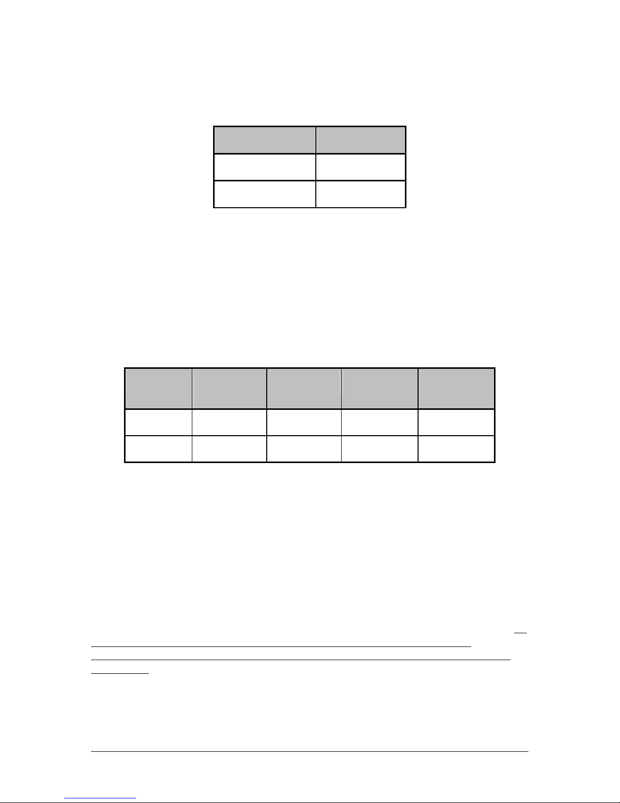
Hop Time 1
Hop Period 8

5
55
5/
//
/8/2007
8/20078/2007
8/2007
16
1616
16
Table
TableTable
Table 6
66
6
–
––
– EEPROM Parameters
EEPROM ParametersEEPROM Parameters
EEPROM Parameters
Parameter
ParameterParameter
Parameter
EEPROM
EEPROMEEPROM
EEPROM
Address
AddressAddress
Address
Length
Len
g
thLen
g
th
Length
(Bytes
(Bytes(Bytes
(Bytes
)
))
)
Range
RangeRange
Range
Default
DefaultDefault
Default
Description
DescriptionDescription
Description
Product ID 00H 40 40 bytes - Product identifier string.
Includes revision information for
software and hardware.
Channel
Number
40H 1 00 – 27h 00h Refer to Table 10
Server/Client
Mode
41H 1 01 – 02h 02h 01h = Server
02h = Client
Baud Rate
Low
42H 1 00 – FFh 05h
Low Byte of the interface baud rate.
Baud Rate
High
43H 1 00 – FFh 00h
High Byte of the interface baud rate.
Control 0 45H 1 00010100
b (14h)
Settings are:
Bit 7 – AeroComm Use Only
AeroComm Use OnlyAeroComm Use Only
AeroComm Use Only
Bit 6 – AeroComm Use Only
AeroComm Use OnlyAeroComm Use Only
AeroComm Use Only
Bit 5 – Sync to Channel
0 = Don't Sync to Channel
1 = Sync to Channel
Bit 4 – AeroComm Use Only
AeroComm Use OnlyAeroComm Use Only
AeroComm Use Only
Bit 3 – Packet Frame
0 = Disable Packet Frame
1 = Use pin 12 as Packet Frame
Bit 2 – AeroComm Use Only
AeroComm Use OnlyAeroComm Use Only
AeroComm Use Only
Bit 1 – RF Delivery
0 = Addressed
1 = Broadcast
Bit 0 – AeroComm Use Only
AeroComm Use OnlyAeroComm Use Only
AeroComm Use Only
Transmit
Retries
4CH 1 01 - FFh 10h Maximum number of times a packet is
sent out when using Addressed
packets.
Broadcast
Attempts
4DH 1 01 – FFh 04h Maximum number of times a packet is
sent out when using Broadcast
packets.
API Control 56H 1 01000011
b = 43h
Settings are:
Bit 7 – AeroComm Use
AeroComm UseAeroComm Use
AeroComm Use Only
OnlyOnly
Only
Bit 6 – RF Architecture
0 = Server-Client
1 = Peer-to-Peer
Bit 5 – AeroComm Use Only
AeroComm Use OnlyAeroComm Use Only
AeroComm Use Only
Bit 4 – Auto Destination

5
55
5/
//
/8/2007
8/20078/2007
8/2007
17
1717
17
0 = Use Destination Address
1 = Automatically set Destination
to Server
Bit 3 – AeroComm Use Only
AeroComm Use OnlyAeroComm Use Only
AeroComm Use Only
Bit 2 – RTS Enable
0 = RTS Ignored
1 = Transceiver obeys RTS
Bit 1 – Duplex Mode
0 = Half Duplex
1 = Full Duplex
Bit 0 – Auto Config
0 = Use EEPROM values
1 = Auto Configure Values
Parameter
ParameterParameter
Parameter
EEPROM
EEPROMEEPROM
EEPROM
Address
AddressAddress
Address
Length
Len
g
thLen
g
th
Length
(Bytes
(Bytes(Bytes
(Bytes
)
))
)
Range
RangeRange
Range
Default
DefaultDefault
Default
Description
DescriptionDescription
Description
Transmit
Retries
4CH 1 01 - FFh 10h Maximum number of times a packet is
sent out when Addressed packets are
selected.
Broadcast
Attempts
4DH 1 01 – FFh 04h Maximum number of times a packet is
sent out when Broadcast packets are
selected.
API Control 56H 1 01000011
b = 43h
Settings are:
Bit 7 – AeroCo
AeroCoAeroCo
AeroComm Use Only
mm Use Onlymm Use Only
mm Use Only
Bit 6 – RF Architecture
0 = Server-Client
1 = Peer-to-Peer
Bit 5 – AeroComm Use Only
AeroComm Use OnlyAeroComm Use Only
AeroComm Use Only
Bit 4 – Auto Destination
0 = Use Destination Address
1 = Automatically set Destination
to Server
Bit 3 – AeroComm Use Only
AeroComm Use OnlyAeroComm Use Only
AeroComm Use Only
Bit 2 – RTS Enable
0 = RTS Ignored
1 = Transceiver obeys RTS
Bit 1 – Duplex Mode
0 = Half Duplex
1 = Full Duplex
Bit 0 – Auto Config
0 = Use EEPROM values
1 = Auto Configure Values
Interface
Timeout
58H 1 01 – FFh F0h Specifies a byte gap timeout, used in
conjunction with RF Packet Size to
determine when a packet coming over
the interface is complete (160 us per

5
55
5/
//
/8/2007
8/20078/2007
8/2007
18
1818
18
increment).
Sync Channel 5AH 1 00 – 3Fh 01h Used to synchronize the hopping of
collocated systems to minimize
interference.
RF Packet Size 5BH 1 01 – 40h 40h Used in conjunction with Interface
Timeout; specifies the maximum size
of an RF packet.
CTS On 5CH 1 01 – FFh C0h CTS will be deasserted (High) when
the transmit buffer contains at least
this many characters.
CTS On
Hysteresis
5DH 1 01 – FFh 80h Once CTS has been deasserted, CTS
will be reasserted (Low) when the
transmit buffer is contains this many
or less characters.
Destination ID 70H 6 6 Bytes Specifies destination for RF packets
System ID 76H 1 00 – FFh 01h Similar to network password. Radios
must have the same system ID to
communicate with each other.
MAC ID 80H 6 6 Bytes Unique IEEE MAC Address
Parameter
ParameterParameter
Parameter
EEPROM
EEPROMEEPROM
EEPROM
Address
AddressAddress
Address
Length
Len
g
thLen
g
th
Length
(Bytes
(Bytes(Bytes
(Bytes
)
))
)
Range
RangeRange
Range
Default
DefaultDefault
Default
Description
DescriptionDescription
Description
Random
Backoff
C3h 1 00 - FFh 00h 00h = Disable Random Backoff
01h = Wait 1-2 packet times, then
retry
03h = Wait 1-4 packet times, then
retry
07h = Wait 1-8 packet times, then
retry
0Fh = Wait 1-16 packet times, then
retry
1Fh = Wait 1-32 packet times, then
retry
3Fh = Wait 1-64 packet times, then
retry
7Fh = Wait 1-128 packet times, then
retry
FFh = Wait 1-256 packet times, then
retry

5
55
5/
//
/8/2007
8/20078/2007
8/2007
19
1919
19
4.2
4.24.2
4.2
C
CC
CONFIGURING THE
ONFIGURING THEONFIGURING THE
ONFIGURING THE AC4424
AC4424AC4424
AC4424 1
1Resetting the AC4424 at any time will exit Configuration or CC Command mode.
No
No
No
Send CC
Command
Send “Enter AT” Command
(Software Configuration)
Take Pin
17 High
Receive
Mode
Send CC
Commands?
Exit
Command
Mode?
Send another
CC
Co
mm
a
n
d?
Use AT
Commands?
Take Pin 17 Low
(Hardware Configuration)
Receive
Mode
In AT
Command
Mode?
Send
“Exit AT”
Command
No
No

5
55
5/
//
/8/2007
8/20078/2007
8/2007
20
2020
20
4.3
4.34.3
4.3
C
CC
COMMAND
OMMANDOMMAND
OMMAND R
RR
REFERENCE
EFERENCEEFERENCE
EFERENCE
Command
CommandCommand
Command Command (All Bytes in Hex)
Command (All Bytes in Hex)Command (All Bytes in Hex)
Command (All Bytes in Hex) Return (All Bytes in Hex)
Return (All Bytes in Hex)Return (All Bytes in Hex)
Return (All Bytes in Hex)
AT Enter
Command
Mode
41h 54h 2Bh 2Bh 2Bh 0Dh CCh 43h 4Fh 4Dh
Exit AT
Command
Mode
CCh 41h 54h 4Fh 0Dh CCh 44h 41h 54h
Status
Request CCh 00h 00h - CCh Firmware
Version
00h: Server In Range
01h: Client In Range
02h: Server Out of Range
03h: Client Out of Range
Change
Channel with
Forced
Acquisition
CCh 02h New
Channel - CCh New
Channel - -
Server/Client CCh 03h
00h – Server in Normal Operation
01h – Client in Normal Operation
02h – Server in Acquisition Sync
03h – Client in Acquisition Sync
CCh Firmware
Version
00h – Server in Normal
Operation
01h – Client in Normal
Operation
02h – Server in
Acquisition Sync
03h – Client in Acquisition
Sync
Sync
Channel CCh 05h New Sync
Channel - CCh
New Sync
Channel - -
Power-Down CCh 06h - - CCh Channel - -
Power-Down
Wake-Up CCh 07h - - CCh Channel - -
Broadcast
Mode CCh 08h 00h: Addressed
01h: Broadcast CCh 00h or 01h - -
Write
Destination
Address
CCh 10h
Byte 4 of
destination’s
MAC
Byte 5 of
destination’s
MAC
Byte 6 of
destination’s
MAC
CCh
Byte 4 of
destination’s
MAC
Byte 5 of
destination’s
MAC
Byte 6 of
destination’s
MAC
Read
Destination
Address
CCh 11h - - CCh
Byte 4 of
destination’s
MAC
Byte 5 of
destination’s
MAC
Byte 6 of
destination’s
MAC
EEPROM
Byte Read CCh C0h Start
Address
Length
(01h – 80h) CCh Start
Address Length Data at
Addresses
EEPROM
Byte Write CCh C1h Address Length
(01h)
Data to be
Written Address Length
(01h) Last byte of Data Written
Soft Reset CCh FFh - - - - - -
Table of contents
Other AeroComm Transceiver manuals

AeroComm
AeroComm CL4490PRO User manual

AeroComm
AeroComm CL4790 User manual

AeroComm
AeroComm AC4424-10 User manual

AeroComm
AeroComm AC4790 User manual

AeroComm
AeroComm PKLR2400S User manual

AeroComm
AeroComm AC5124 User manual

AeroComm
AeroComm CL4490-1000 User manual

AeroComm
AeroComm AC4490 User manual

AeroComm
AeroComm AC4490 User manual

AeroComm
AeroComm TRANSCEIVER ZB2430 User manual


