AeroFlash CanopyFlasher LITE User manual

A e r o F L A S H
PowerBox (PRO)
“See and Avoid” starts with being SEEN…
CanopyFlasher LITE, AeroFlash BASIC,
PowerBox, PowerBox PRO.
Installation and Operating Manual
Revision 3 - August 2021
1

www.AeroFLASH.de “See and Avoid” starts with being SEEN Rev 3 - AUG 2021
1. Important notices and limited warranty
2. Introduction
2.1 Terminology
3. System overview and installation planning
3.1 Scope of delivery
3.2 Status LEDs
3.3 Flashing logic
3.4 Power consumption
3.5 Power supply
3.6 Dimensions and weights
3.7 Temperature specifications and cooling requirements
3.8 Humidity
3.9 Mounting requirements
4. Installation instructions and examples
4.1 Installation and connection of PowerBox (PRO)
4.2 Mounting the CanopyFlasher
4.3 Vertical-opening canopy installations
4.4 Side-opening canopy installations - general
4.5 Side-opening canopy installations - Schempp Hirth
4.6 Installation of the FuselageFlasher and PowerBox PRO
4.7 Installation of the OFF/ON switch
4.8 Post-installation system check
5. Troubleshooting
6. Revision history
7. Appendix
7.1 AeroFlash product comparison
2

www.AeroFLASH.de “See and Avoid” starts with being SEEN Rev 3 - AUG 2021
1. Important notices and limited warranty
The AeroFlash system is designed for VFR use only, as an aid to collision
avoidance. AeroFlash is in no way designed for operation in IFR or IMC conditions.
Installing AeroFlash does not refrain from exercising the regular See and Avoid
procedures.
The pilot is always responsible for this action and may NEVER fully rely on being
seen by the other traffic. AeroFlash is only an aid to enhance visibility of your
aircraft.
The installation of an AeroFlash system must comply with EASA regulations as
per Standard Change CS-SC036a “INSTALLATION OF VISUAL AWARENESS
LIGHTS”:click here for the link to the EASA document.
Information in this document is subject to change without notice. AeroFlash
reserves the right to change or improve their products and to make changes in
the content of this material without obligation to notify any person or
organisation of such changes or improvements.
A yellow triangle is shown for parts of the manual which should be read
very carefully and are important for operating the system.
Notes with a red triangle describe procedures which are critical and may
result in serious damage or any other critical situation.
A bulb icon is shown when a useful hint is provided to the reader.
This AeroFlash product is warranted to be free from defects in materials or
workmanship for two years from the date of purchase. Within this period,
AeroFlash will, at its sole discretion, repair or replace any components that fail in
normal use. Such repairs or replacement will be made at no charge to the
customer for parts and labour, provided that the customer shall be responsible for
any transportation cost. This warranty does not cover failures due to abuse,
misuse, accident, or unauthorised alterations or repairs.
THE WARRANTIES AND REMEDIES CONTAINED HEREIN ARE EXCLUSIVE AND IN
LIEU OF ALL OTHER WARRANTIES EXPRESSED OR IMPLIED OR STATUTORY,
INCLUDING ANY LIABILITY ARISING UNDER ANY WARRANTY OF
MERCHANTABILITY OR FITNESS FOR A PARTICULAR PURPOSE, STATUTORY OR
OTHERWISE. THIS WARRANTY GIVES YOU SPECIFIC LEGAL RIGHTS, WHICH MAY
VARY FROM STATE TO STATE. IN NO EVENT SHALL AEROFLASH BE LIABLE FOR
ANY INCIDENTAL, SPECIAL, INDIRECT OR CONSEQUENTIAL DAMAGES,
WHETHER RESULTING FROM THE USE, MISUSE, OR INABILITY TO USE THIS
PRODUCT OR FROM DEFECTS IN THE PRODUCT. Some states do not allow the
3
www.AeroFLASH.de “See and Avoid” starts with being SEEN Rev 3 - AUG 2021
exclusion of incidental or consequential damages, so the above limitations may
not apply to you. AeroFlash retains the exclusive right to repair or replace the unit
or firmware, or to offer a full refund of the purchase price, at its sole discretion.
SUCH REMEDY SHALL BE YOUR SOLE AND EXCLUSIVE REMEDY FOR ANY
BREACH OF WARRANTY.
To obtain warranty service, contact your local AeroFlash dealer or contact
AeroFlash directly.
2. Introduction
A printed version of this installation manual may be in grayscale. Some figures
and diagrams are coloured, like coding of power- and data wires. Please refer to
the electronic version to see the correct colours. Confusion of color coded wires
may cause serious system damage and is not covered by the limited warranty.
The latest electronic version of this manual can be downloaded from
www.AeroFLASH.de, section downloads - manuals. Please refer to your hardware
version if certain items apply to your device.
This manual will guide you through the installation process of all systems,
components, basic setup and check of the system.
If in any case confusion exists, please contact us for a clarification.
Before using any part of the system, please read and understand this
Installation and Operating manual.
There are no serviceable parts within the unit, hence the unit must be
taken to the dealer or factory for service.
Opening of any AeroFlash product by the user will void all warranty!
Never plug any unauthorized devices into the DB9 connectors! These
will certainly cause serious damage to the PowerBox, CanopyFlasher
and/or your computer. PowerBox cannot be connected to your
computer!
2.1 Terminology
PowerBox: stand-alone power supply and Flasher activator for
CanopyFlasher LITE only.
PowerBox PRO: all-in-one, stand-alone power supply and synchronised
flashing sequencing for one CanopyFlasher LITE and one FuselageFlasher.
CanopyFlasher: canopy mounted forward flashing device.
4
www.AeroFLASH.de “See and Avoid” starts with being SEEN Rev 3 - AUG 2021
FuselageFlasher: top or bottom fuselage external mounted, 360º by 180º
flashing device. This may also be an “external flasher” - not necessarily
supplied by AeroFlash (read further for compatibility).
CanopyConnector: the opposite 7-pin connector that is fitted to the
CanopyFlasher, and is mounted on the canopy or canopy frame, supplying
power and data between Nexus/PowerBox and the CanopyFlasher.
SidewallContact: a 7-pin contact fitted to the Nexus/PowerBox cable set,
which is to be mounted on the interior sidewall. It is universal for every
glider with a side opening canopy. It connects to the CanopyFlasher.
CanopyContact: a 7-pin contact fitted to the Nexus/PowerBox cable set,
which is to be mounted on the instrument panel cover, specially made for
Schempp-Hirth gliders, which connects to the CanopyFlasher. SH-glider
owners may also choose the SidewallContact if they prefer not to drill a
hole in the instrument panel cover.
3. System overview and installation planning
The CanopyFlasher LITE and AeroFlash BASIC Visual Awareness Light
system features multiple parts:
The system is designed to be
plug-and-fly. It comes complete
with everything you need. No
additional wiring, splitters or
soldering is required, other than connecting it to your aircraft’s power
supply. Typical installations can be done in 60 to 120 minutes. For an
overview of the scope of delivery please refer to chapter 3.1.
5
www.AeroFLASH.de “See and Avoid” starts with being SEEN Rev 3 - AUG 2021
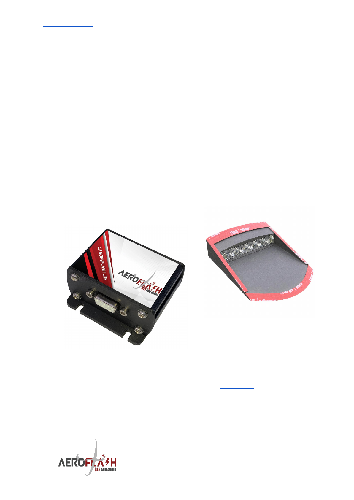
PowerBox (PRO)
PowerBox (PRO) is fully stand-alone.
PowerBox powers the CanopyFlasher
LEDs and provides flashing timing.
PowerBox (PRO) is not connectable
to Flarm and does not have
Bluetooth features. It’s a simple,
cost-effective solution for those who
do not need all the “luxury” features.
PowerBox PRO as part of AeroFlash
BASIC kit can also supply power to
one FuselageFlasher and provides
optimised synchronised flashing
sequencing.
PowerBox (PRO) continuously monitors the temperature of the
CanopyFlasher system. If an overheat situation is present, it automatically
shuts down the system to prevent damage to the system and to your
expensive canopy. After a short cooling the system will restart
automatically if conditions permit. Don’t worry, the system generally
doesn’t get very warm in flight, but in summer conditions on ground
without air flow your glider is well protected.
A neat removable screw-terminal system allows a quick connection of the
power wires, and easy removal when needed. No need for soldering;
everything is plug-and-fly.
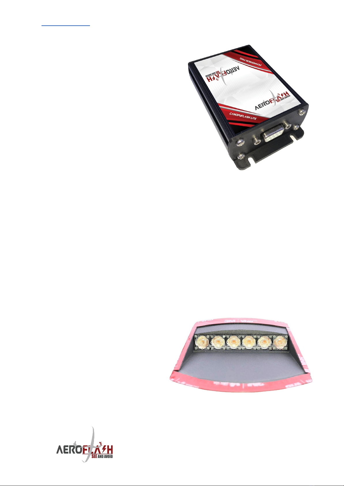
CanopyFlasher - canopy mounted, forward-facing flasher
CanopyFlasher is made from a high strength, UV-resistant ABS based
polymer. The unit is delivered as standard painted in a high quality, matte
“Space Grey” (Nextel like) finish.
Optionally it can be delivered in
different colors.
The heart of the CanopyFlasher
is the array of 6 extremely
bright CREE LEDs emitting
approximately 4000-4500
(red/white) Lumens, with
powerful, oval lenses; 2 beams
orientated vertically, and 4
beams orientated horizontally.
This makes the Flasher well visible at distances of even up to 3500m, ±30
degrees above and below- and up to ±45 degrees left and right of the nose.
6
www.AeroFLASH.de “See and Avoid” starts with being SEEN Rev 3 - AUG 2021
The CanopyFlasher system incorporated many safety features, like heat
sinks, a temperature sensor to prevent overheat conditions and two status
LEDs for indication of the operating modes.
Never look straight into the illuminated CREE LEDs as this will
certainly result in temporary blindness, with risk of permanent
damage to the eye sight! It is your responsibility to inform
anyone who is not familiar with this system.
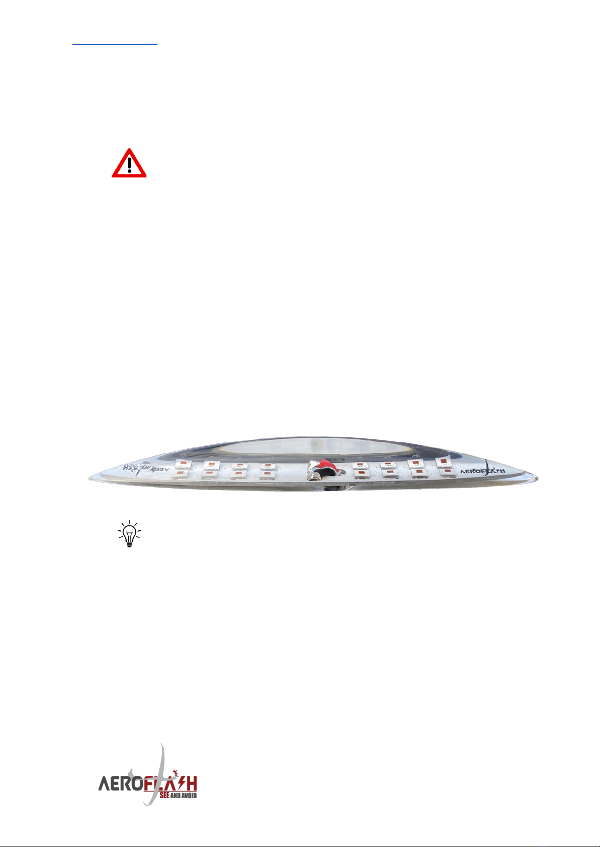
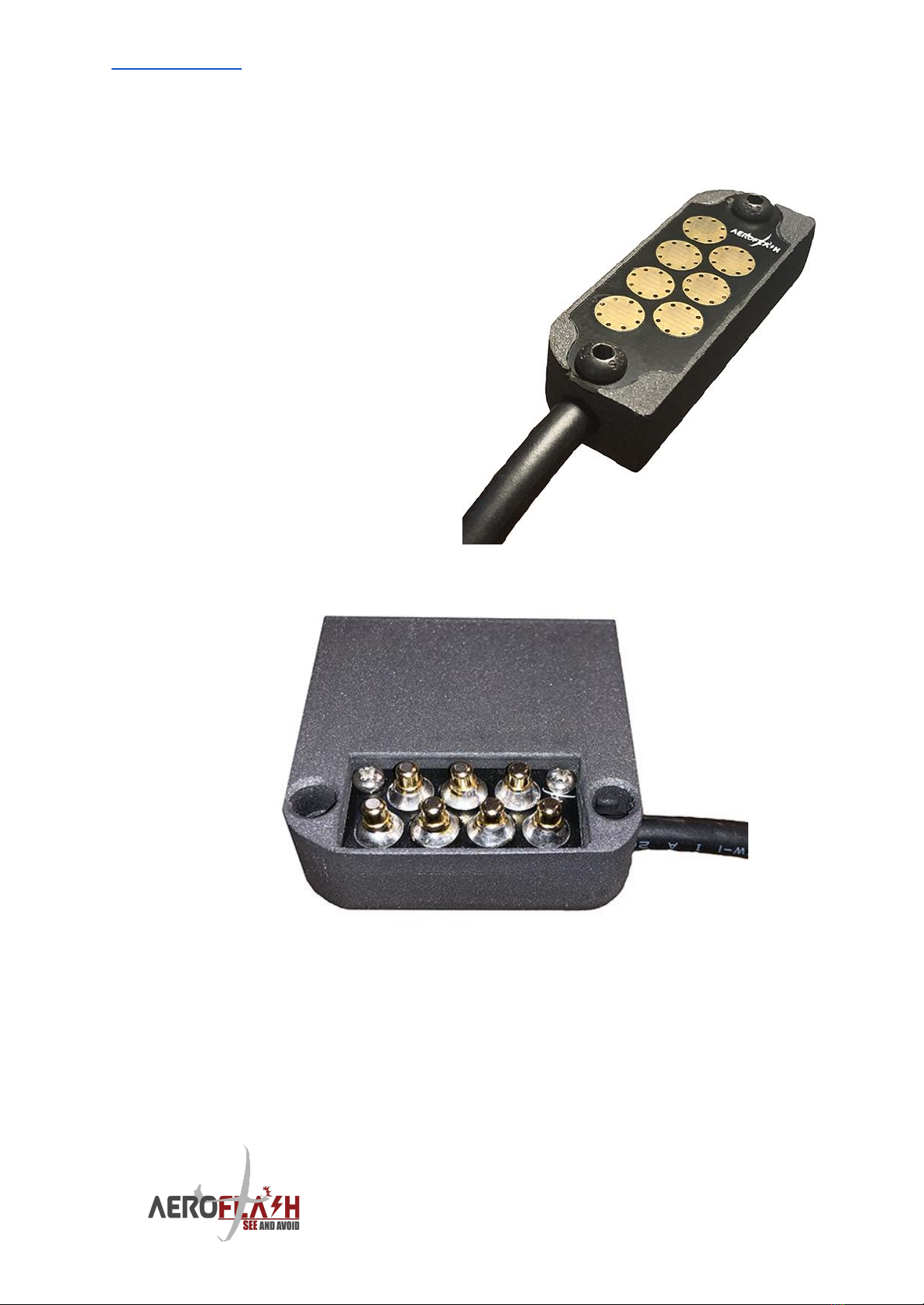
FuselageFlasher - 360º external, top/bottom fuselage mounted flasher
The PowerBox system features an additional flasher data port for
connection to our Fusion/FuselageFlasher system. The FuselageFlasher is
made out of a very strong, super clear UV resistant epoxy and features 16
extremely bright CREE LEDs, emitting approximately 7500-8500
(red/white) Lumens. It can be installed on the top or bottom of the
fuselage, flashing in a 360 degrees view. The FuselageFlasher is extremely
sleek and aerodynamic, measured at only 110mm long x 15mm wide x
11mm high. Only one small hole of 5mm is required for the three power
wires. Mounting of the flasher can be done simply with the (included)
super strong 3M double sided adhesive foam tape, sealed off with some
silicone mounting kit for weather-proofing. A simple and sturdy mounting,
but less “permanent” than other solutions.
Install the FuselageFlasher on one of the wheel- or engine bay
doors (close to the center-line of the fuselage) to avoid drilling
in the fuselage. This is the quickest and easiest installation
with the least amount of impact on the airframe.
7
www.AeroFLASH.de “See and Avoid” starts with being SEEN Rev 3 - AUG 2021
3.1 Scope of delivery
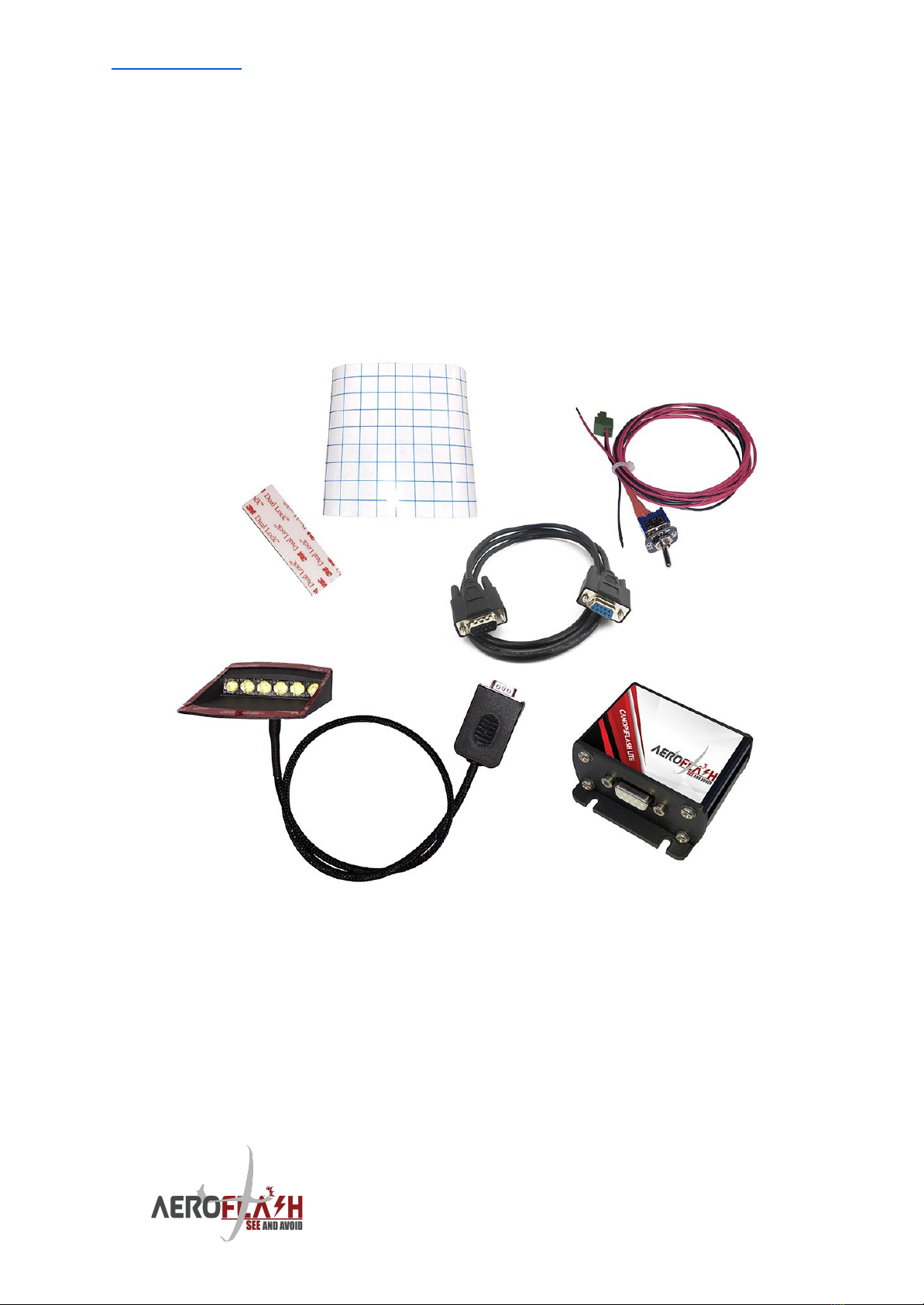
CanopyFlasher LITE system:
1x PowerBox device.
1x CanopyFlasher with 3M double sided adhesive foam tape pre-applied
and cable set***.
1x DB9 - DB9 extension cable (1 meter).
1x Dual Lock adhesive tape for mounting of the PowerBox.
1x Vinyl sticker template for aligning the CanopyFlasher during installation.
1x 1 meter power cable with ON/OFF switch and marking/label.
*** The cable set version and length depends on the canopy opening
direction:
- Vertical opening canopies receive a DB9 connector set.
- Other glareshield/panel mounted DB9-connection solutions for
side-opening canopies on special request.
8
www.AeroFLASH.de “See and Avoid” starts with being SEEN Rev 3 - AUG 2021
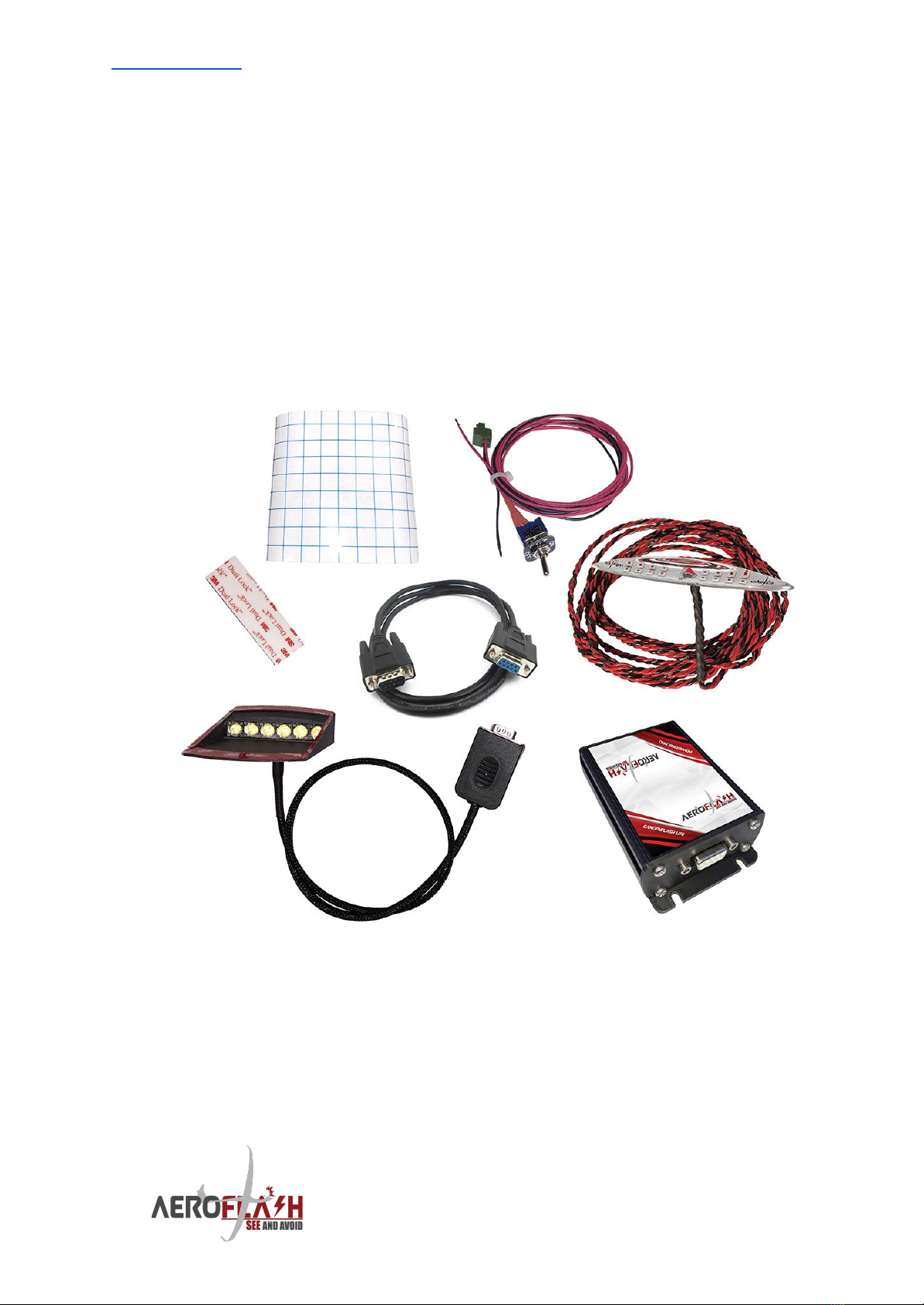
AeroFlash BASIC system:
1x PowerBox PRO device.
1x FuselageFlasher, with 3M double sided adhesive foam tape pre-applied,
with 4 meter pre-attached AWG20 wiring (3 wires: red, red, black) - other
lengths available on request.
1x CanopyFlasher with 3M double sided adhesive foam tape pre-applied
and cable set***.
1x DB9 - DB9 extension cable (1 meter).
1x Dual Lock adhesive tape for mounting of the PowerBox PRO.
1x Vinyl sticker template for aligning the CanopyFlasher during installation.
1x 1 meter power cable with ON/OFF switch and marking/label.
*** The cable set version and length depends on the canopy opening
direction:
- Vertical opening canopies receive a DB9 connector set.
- Other glareshield/panel mounted DB9-connection solutions for
side-opening canopies on special request.
9
www.AeroFLASH.de “See and Avoid” starts with being SEEN Rev 3 - AUG 2021
NOT included, optionally available and may be required for the
installation:
Fuse/circuit breaker, 2A or 3A - available from us separately.
Silicone sealant/kit (for weather-proofing the FuselageFlasher).
Additional power cable. Crimp or soldering tools. Cable ties, cable clips.
3.2 Status LEDs
The CanopyFlasher LITE features two different colored status LEDs
indicating the following:
Green status LED:
Off
System switched off.
Steady
System operating normally (flashing).
Blinking (1 Hz)
Flasher temperature high, overheat protection active.
Red status LED:
Off
Flasher temperature normal
Blinking (1 Hz)
Flasher temperature high, overheat protection active.
GREEN and RED status LEDs blinking rapidly (2Hz) at the
same time indicate that an overheat condition is detected.
Subsequently, the CanopyFlasher is deactivated until the
overheat condition disappears.
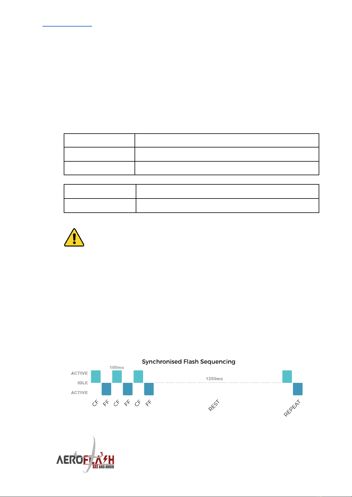
3.3 Flashing logic
PowerBox (PRO) automatically starts flashing once switched on. The
CanopyFlasher and FuselageFlasher never flash at the same time. They
each alternate every pulse, meaning only one flasher is draining power at
the same time, resulting in lower peak currents and less stress on your
battery.
PowerBox (PRO) flashes at 3 flash-cycles followed by a rest/cooling cycle of
1250 milliseconds, continuously until switched off. The flashing sequencing
or timing cannot be changed.
10

www.AeroFLASH.de “See and Avoid” starts with being SEEN Rev 3 - AUG 2021
3.4 Power consumption
Due to the efficient technology and smart synchronised flash-sequencing
we incorporated in PowerBox (PRO) and all AeroFlash products, power
consumption is very reasonable and should not be an obstacle to installing
AeroFlash systems. Typical power consumption will result in an average
power consumption of only 210-720mAh (milliamps per hour).
System situation & setup
Power usage per hour
CanopyFlasher LITE
(PowerBox + CanopyFlasher.
3-Flashes per 1250 milliseconds).
±210mAh
AeroFlash BASIC
(PowerBox PRO + CanopyFlasher + FuselageFlasher.
2 x 3-Synchronised flashes per 1250 milliseconds).
±720mAh
AeroFlash can strongly recommend special AIRNERGY high
capacity LiNiMnCoO2 (NMC) batteries, which double capacity
versus LiFePO4 (LFP) for the same size and even lower weight!
3.5 Power supply
PowerBox (PRO) systems accept a power input of 10V to 20V DC.
There is NO fuse inside, nor included with the system. Suitable fuses or
circuit breakers are available from our dealers, or from AeroFlash directly.
PowerBox (PRO) requires a minimum thickness of 20AWG wire (standard
supplied), and a circuit breaker rated at 2 or 3A:
System setup
Circuit breaker requirement
CanopyFlash LITE + PowerBox
2A
CanopyFlash LITE +
FuselageFlasher + PowerBox
PRO(basic)
3A
We strongly advise to install an automatic circuit breaker that
can be tripped manually, rather than a fast blowing glass-fuse.
These automatic circuit breakers are available from AeroFlash
webshop or our dealers. Contact us for more information.
11

www.AeroFLASH.de “See and Avoid” starts with being SEEN Rev 3 - AUG 2021
3.6 Dimensions and weights
PowerBox:
Dimensions LWH: 100 x 63 x 31mm (including mounting flanges).
Weight: ±100 grams.
PowerBox PRO:
Dimensions LWH: 100 x 63 x 31mm (including mounting flanges).
Weight: ±190 grams.
CanopyFlasher:
Dimensions LWH: 90 x 64 x 23mm (±10%, length/height varies per glider
type).
Weight: ±100 grams with 100cm cable.
FuselageFlasher:
Dimensions LWH: 110 x 15 x 11mm (including mounting-foam tape).
Weight: ±15 grams without cable / ±95 grams with 4m cable.
3.7 Temperature specifications and cooling requirements
All AeroFlash components are designed to operate in temperatures
ranging from -30 to +60ºC. These temperature limitations depend on the
actual ambient conditions. Generally with high-summer (>30°C)
temperatures some precautions must be observed.
Maximum operating times at high ambient temperatures:
CanopyFlasher
FuselageFlasher
On ground
In flight
On ground
In flight
Max 10 minutes
50ºC OAT
Max 5 minutes!
50ºC OAT
(temperature
sensor prevents
overheating in
normal conditions)
(with
forward
canopy
airflow open)
(limited*
temperature
protection installed!)
(no additional
cooling
requirements)
*Temperature protection linked to CanopyFlasher
temperature.
In flight there are no special precautions that must be made for cooling of
the system. Multiple heat sinks, cooling slots and a temperature sensor are
built-in the CanopyFlasher to monitor the system and automatically shut it
down when an overheat condition is experienced (LED temperature of
70ºC). Ensure to never block the cooling slots.
12

www.AeroFLASH.de “See and Avoid” starts with being SEEN Rev 3 - AUG 2021
Generally even in hot summer conditions, the airflow from the front of the
canopy is more than sufficient to cool the system and the system will not
even come close to the maximum operating temperature of 70ºC. These
protections are built-in solely to prevent aircraft- and system damage in
case of a failure of the electronics.
In high ambient temperatures (and strong sunlight), the
CanopyFlasher and FuselageFlasher LEDs may become quite
warm when operated continuously on the ground, without
cooling from the (canopy) airflow ventilation. Do not rely on
the temperature sensor and avoid activating the system on
the ground for prolonged times. Serious damage to the
flasher, as well as to the fuselage (overheating) may occur due
to the lack of air-cooling, especially in strong sunlight and
high ambient temperatures!
Please always use a canopy cover whenever the glider is not
in use, and switch off the power supply to the system. This will
benefit the life-time of all the components due to less
exposure to heat and UV light.
3.8 Humidity
PowerBox (PRO), CanopyFlasher and FuselageFlashers are designed to
operate in humidity ranging from 0 to 95%.
The FuselageFlasher is waterproof. Please refer to the specific installation
instructions in chapter 4.8 for more details.
3.9 Mounting requirements
PowerBox (PRO) may be mounted with up to 4 screws, or by using the
supplied 3M “Dual Lock” super strong double sided adhesive tape and
some cable ties.
In any case AeroFlash should be mounted in accordance with the
installation requirements as per (a.o.) CS-SC036a and CS-SC402b.
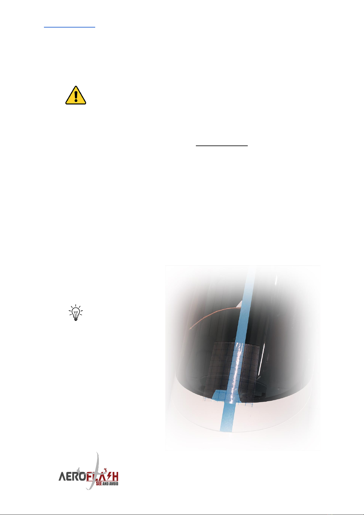
The CanopyFlasher comes prepared with super strong black 3M double
sided adhesive foam tape. It is strongly recommended to use this black
tape as it blocks out any reflections that may appear in the canopy when
the flasher is activated. This 3M tape is safe to use on plexiglass.
13
www.AeroFLASH.de “See and Avoid” starts with being SEEN Rev 3 - AUG 2021
4. Installation instructions and examples
The installation of an AeroFlash system must comply with EASA
regulations as per Standard Change CS-SC036a “INSTALLATION OF
VISUAL AWARENESS LIGHTS”:click here for the link to the EASA
document.
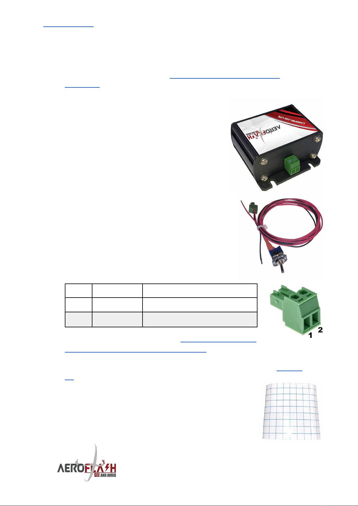
4.1 Installation and connection of
PowerBox (PRO)
Find a suitable location for the PowerBox (PRO)
unit. It may be required to make some brackets
and use the mounting flanges to mount it with
two or four screws. Avoid over-tightening of
screws on the plastic flanges, as the plastic may
break! It may also be possible to use some cable
ties to mount the PowerBox (PRO) to another
device, or use a piece of the 3M Dual Lock
adhesive tape that we included.
Wiring up the PowerBox
The cable set comes already prepared with a
pluggable 2-pin Camdenboss CTB922HE/2 power
connector. In case you wish to shorten the wires; it
uses the following pinout which must be carefully
observed. Wrong connection will permanently
damage the device.
Pin
Color
Description
1
Black
Ground INPUT (GND, negative) (AWG20)
2
Red
+10 to 20V INPUT (VCC, positive) (AWG20)
For PowerBox PRO pinout refer to chapter 4.6 Installation
of the FuselageFlasher and PowerBox PRO.
Install a fuse/circuit breaker. Observe the tripping current as per chapter
3.5, and connect these to the glider’s power network.
4.2 Mounting the CanopyFlasher
Mark the centerline of the canopy with a piece of white
PVC tape. Please be cautious to use the yaw string as
centerline reference, as often these are not placed in the
exact center!
14
www.AeroFLASH.de “See and Avoid” starts with being SEEN Rev 3 - AUG 2021
Using the supplied vinyl grid sticker may make it easier to align the
CanopyFlasher so it’s perfectly straight. It may be very difficult to see the
alignment once you try to stick it to the canopy from the inside.
Before permanently mounting the CanopyFlasher, check if
the selected location does not intervene with the canopy
ventilation mechanism!
After marking the correct position, it may be easiest to remove the canopy
and place it upside down on a soft/safe location.
Clean the surface of the canopy with a non-aggressive cleaning agent to
remove dirt and grease, to ensure the adhesive tape sticks well. Normally
water and a bit of soap is fine.
The CanopyFlasher is pre-applied with black 3M VHB double sided
adhesive foam tape. It is strongly recommended to use this black tape as it
blocks out any reflections that may appear in the canopy when the flasher
is activated. This 3M tape is safe to use on plexiglass canopies.
Remove the film and carefully stick the CanopyFlasher against the canopy.
Be careful not to apply too much force to the canopy, but make sure the
tape is attached well in all corners. If there is a small air bubble between
the canopy and the tape, don’t attempt to remove the CanopyFlasher. Most
likely the bubble will disappear in a couple of days or with some warmth
from the sun.
The 3M VHB
double sided
adhesive foam
tape is best
applied at
temperatures
above 15ºC.
15
www.AeroFLASH.de “See and Avoid” starts with being SEEN Rev 3 - AUG 2021
4.3 Vertical-opening canopy installations
This section mostly applies to JS, Schleicher, HPH,
Rolladen Schneider (LS) and Glaser Dirks (DG)
gliders. In some side-opening canopy installations it
may be preferential to use the vertical-opening
cable set solution. This applies to for example
DG500/DG1000, (Twin) Astir and Standard Cirrus, and
perhaps other gliders.
Vertically opening canopies need an easy to attach, but most
importantly, easy to DETACH connector. When jettisoning the
canopy in case of an emergency, our connectors are designed
to easily separate. Do not modify these connectors, or install a
different type.
Now that you have mounted the CanopyFlasher, it’s time to take care of the
cable set.
The AeroFlash installation consists of commonly seen male and female
DB9 (D SUB 9) type connectors for the data cables (status LEDs and
temperature sensor), and for the power supply of the CanopyFlasher. It is
sturdy, easy to attach, separate, and highly suited for the currents.
Step 1
The DB9 connector comes pre-attached to the CanopyFlasher. In certain
installations there may be required to make a hole through the instrument
panel cover to feed the cable through. Of course it’s highly desirable to
keep this hole as small as possible. Our DB9 connector is fitted with certain
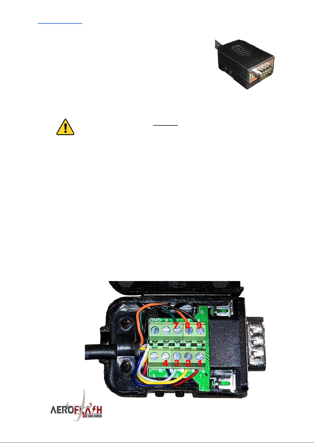
easy to install screw-type terminals (no soldering required!). Open the
connector cover by loosening the clip on the side with a screwdriver and
take note of the color coding and pinout of the connector:
16

www.AeroFLASH.de “See and Avoid” starts with being SEEN Rev 3 - AUG 2021
Pin
Wire color
Wire description
1
RED
Flasher +9-20V VCC/Positive (internally connected with pin 6)
2
YELLOW
Temperature sensor +5V
3
WHITE
Temperature sensor signal
4
BLUE
Common signal GND (ISOLATE FROM PIN 9!)
5
-
Flasher GND/Negative (internally connected with pin 9)
6
-
Flasher +9-20V VCC/Positive (internally connected with pin 1)
7
GREEN
Status LED 1 (green LED)
8
ORANGE
Status LED 2 (red LED)
9
BLACK
Flasher GND/Negative (internally connected with pin 5)
Loosen the screws on the DB9 terminals to temporarily remove the wires. It
is now possible to feed the data cable through a hole of approximately
5mm.
Carefully replace the wires in the original pinout and tighten the screw
terminals. Do not overtighten the screws to avoid damage to the threads.
Replace the connector cover.
You may use the supplied DB9 female - DB9 male extension cable (1 meter)
to more optimally route the cables underneath the instrument panel cover.
In case you need a different length, any 1:1 DB9 or RS232 extension cable
will work.
If using the supplied extension cable, it’s recommended to
secure both sides of the cable to a sturdy point on the frame
of the instrument panel or canopy with a cable tie. In case
someone forgets to manually separate the connectors during
regular maintenance/removal of the canopy, no chance exists
to accidentally damage the CanopyFlasher cable.
Step 2
In case of a PowerBox PRO installation, continue with chapter 4.6
Installation of the FuselageFlasher and PowerBox PRO, or continue to 4.7
Installation of the OFF/ON switch.
Depending on the glider type, you may have removed the canopy. You can
now reinstall the canopy as the installation is nearly complete and we need
to correctly orientate the OFF/ON switch and test its function. Make sure
not to forget to attach the system’s cables.
17
www.AeroFLASH.de “See and Avoid” starts with being SEEN Rev 3 - AUG 2021
4.4 Side-opening canopy installations - general
Each glider type requires a
specially designed connector
solution. This is unique to every
different glider type. A brief
installation instruction manual
together with installation example
pictures will be delivered together
with these orders.
Below / on the side are a few
examples suitable for Grob G102
Club/Standard Astir and G103 Twin
Astir gliders.
If your glider is not yet supported,
please contact us to develop a
solution together.
18
www.AeroFLASH.de “See and Avoid” starts with being SEEN Rev 3 - AUG 2021
4.5 Side-opening canopy installations - Schempp-Hirth
This section mostly applies
(but is not limited to, or
possible for all) to
Schempp-Hirth gliders.
For example Cirrus gliders
require a vertical-opening
canopy connector solution.
Schempp-Hirth glider owners
may also choose to install a
panel mounted DB9
connector option when the
instrument panel cover has a
lot of play. It must be fairly
sturdy in order to work
well/reliable.
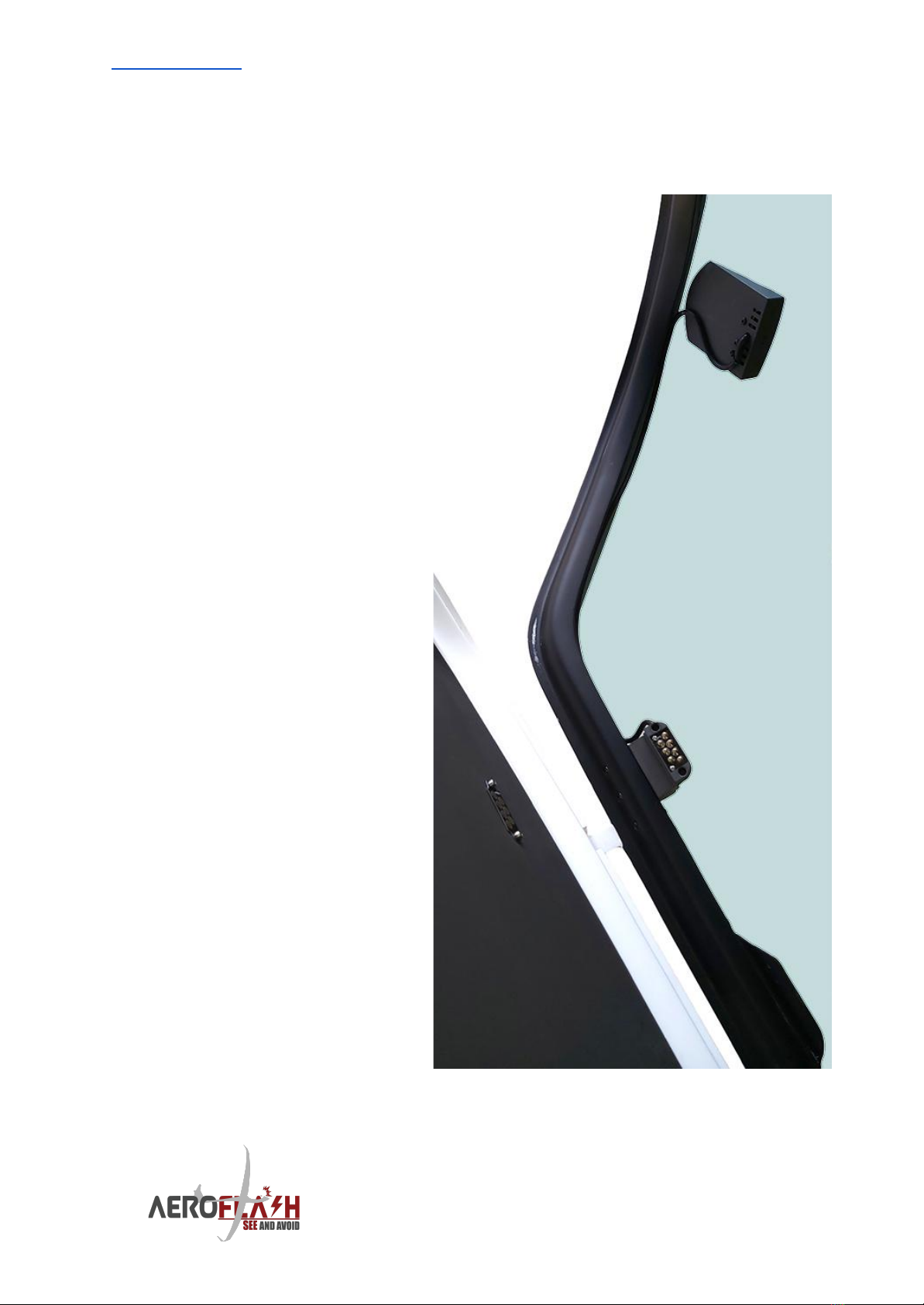
For safety reasons, we require
a connector that is easily
DETACHED in case of an
emergency. We designed a
special 7-pin spring loaded
connector to be mounted on
the glareshield/panel cover
and the canopy edge, which
requires absolutely no force to
separate. There is no need to
solder any wiring, however you
will need to install the
connector in a suitable
location and drill some holes.
19

www.AeroFLASH.de “See and Avoid” starts with being SEEN Rev 3 - AUG 2021
Find a suitable place to install the 7-pin CanopyConnector that is attached
to the CanopyFlasher. You need to install this CanopyConnector to the
canopy frame using one of the supplied mountings at a location where
when the canopy is closed, it can make good contact with the opposite
part. This should be done on the
right side of the instrument panel
cover. Ideally there should be no or
limited movement of the panel
cover. A good place is close to the
instrument panel, and near the
canopy hinge.
The opposite connector part (called
PanelContact) is already attached
to the PowerBox’s cable set and is
ideally mounted through a small
hole (approximately 25 x 10mm) in
the instrument panel top cover,
using the supplied stainless steel
M3 cylinder head bolts. These bolts
are designed to align correctly with
the CanopyConnector.
Please note that certain
glider types may use or
require a “vertical-opening
canopy installation”, even
though they have
side-opening canopies.
This applies to for example:
DG500/DG1000, Standard
Cirrus, etc, and is due to
the difficulty finding a
suitable location for
installing this
CanopyConnector.
20
This manual suits for next models
3
Table of contents
Other AeroFlash Lighting Equipment manuals


