AeroFlash Nexus PRO User manual

N E X U S P R O
A E R O F L A S H P L U S
“See and Avoid” starts with being SEEN…
Valid for:
CanopyFlasher + FuselageFlasher + Nexus PRO.
AeroFlash PLUS kit.
Installation and Operating Manual
Revision 2 - February 2022
1

www.AeroFLASH.de “See and Avoid” starts with being SEEN Rev 2 - FEB 2022
1. Important notices and limited warranty
2. Introduction
2.1 Terminology
3. System overview and installation planning
3.1 System overview
3.1.1 RJ12 input ports
3.1.2 Mini-USB connector
3.1.3 Status LEDs
3.1.4 Auto/ON mode logic - in flight
3.1.5 Auto/ON mode logic - on ground
3.1.6 Hazard mode logic
3.2 Power consumption
3.3 Power supply
3.4 Dimensions and weights
3.5 Temperature specifications
3.6 Cooling requirements
3.7 Humidity
3.8 Mounting requirements
4. Installation instructions and examples
4.1 Scope of delivery
4.2 Installation of the Nexus PRO unit
4.3 Connection to a Flarm
4.4 Mounting the CanopyFlasher
4.5 Vertical-opening canopy installations
4.6 Side-opening canopy installations - general
4.7 Side-opening canopy installations - Schempp Hirth
4.8 Installation of the FuselageFlasher
4.9 Installation of the Auto/ON switch
4.10 Post-installation system check
4.11 Installation of a second FuselageFlasher and Fusion unit
5. Firmware configurations and updates
5.1 Windows PC tool
6. Troubleshooting
6.1 Q: My Flarm is broken/removed and I want to use the system without AUTO-mode
6.2 Q: My CanopyFlasher keeps blinking green
6.3 Q: AUTO-mode does not seem to work
6.4 Q: My system is showing erratic flashing behavior
6.5 Q: Q: I need to remove the CanopyFlasher from the canopy. How do I do this safely?
7. Revision history
8. Appendix
8.1 Product comparison
8.2 DG-single seater cable set differences
8.3 Fixed canopy cable set differences
2
www.AeroFLASH.de “See and Avoid” starts with being SEEN Rev 2 - FEB 2022
1. Important notices and limited warranty
The AeroFlash system is designed for VFR use only, as an aid to collision
avoidance. AeroFlash is in no way designed for operation in IFR or IMC conditions.
Installing AeroFlash does not refrain from exercising the regular See and Avoid
procedures.
The pilot is always responsible for this action and may NEVER fully rely on being
seen by the other traffic. AeroFlash is only an aid to enhance visibility of your
aircraft.
The installation of an AeroFlash system must comply with EASA regulations as
per Standard Change CS-SC036a “INSTALLATION OF VISUAL AWARENESS
LIGHTS”:click here for the link to the EASA document.
Information in this document is subject to change without notice. AeroFlash
reserves the right to change or improve their products and to make changes in
the content of this material without obligation to notify any person or
organisation of such changes or improvements.
If in any case confusion exists, please contact us for a clarification.
A yellow triangle is shown for parts of the manual which should be read
very carefully and are important for operating the system.
Notes with a red triangle describe procedures which are critical and may
result in serious damage or any other critical situation.
A bulb icon is shown when a useful hint is provided to the reader.
This AeroFlash product is warranted to be free from defects in materials or
workmanship for two years from the date of purchase. Within this period,
AeroFlash will, at its sole discretion, repair or replace any components that fail in
normal use. Such repairs or replacement will be made at no charge to the
customer for parts and labour, provided that the customer shall be responsible for
any transportation cost. This warranty does not cover failures due to abuse,
misuse, accident, or unauthorised alterations or repairs.
THE WARRANTIES AND REMEDIES CONTAINED HEREIN ARE EXCLUSIVE AND IN
LIEU OF ALL OTHER WARRANTIES EXPRESSED OR IMPLIED OR STATUTORY,
INCLUDING ANY LIABILITY ARISING UNDER ANY WARRANTY OF
MERCHANTABILITY OR FITNESS FOR A PARTICULAR PURPOSE, STATUTORY OR
OTHERWISE. THIS WARRANTY GIVES YOU SPECIFIC LEGAL RIGHTS, WHICH MAY
3
www.AeroFLASH.de “See and Avoid” starts with being SEEN Rev 2 - FEB 2022
VARY FROM STATE TO STATE. IN NO EVENT SHALL AEROFLASH BE LIABLE FOR
ANY INCIDENTAL, SPECIAL, INDIRECT OR CONSEQUENTIAL DAMAGES,
WHETHER RESULTING FROM THE USE, MISUSE, OR INABILITY TO USE THIS
PRODUCT OR FROM DEFECTS IN THE PRODUCT. Some states do not allow the
exclusion of incidental or consequential damages, so the above limitations may
not apply to you. AeroFlash retains the exclusive right to repair or replace the unit
or firmware, or to offer a full refund of the purchase price, at its sole discretion.
SUCH REMEDY SHALL BE YOUR SOLE AND EXCLUSIVE REMEDY FOR ANY
BREACH OF WARRANTY.
To obtain warranty service, contact your local AeroFlash dealer or contact
AeroFlash directly.
2. Introduction
A printed version of this installation manual may be in grayscale. Some figures
and diagrams are coloured, like coding of power- and data wires. Please refer to
the electronic version to see the correct colours. Confusion of color coded wires
may cause serious system damage and is not covered by the limited warranty.
The latest electronic version of this manual can be downloaded from
www.AeroFLASH.de, section downloads - manuals. Please refer to your hardware
version if certain items apply to your device.
This manual will guide you through the installation process of all systems,
components, basic setup and check of the system.
Before using any part of the system, please read and understand this
Installation and Operating manual.
There are no serviceable parts within the unit, hence the unit must be
taken to the dealer or factory for service.
Opening of the Nexus and/or Fusion unit by the user will void all warranty!
Never plug any unauthorized devices into the mini-USB or DB9
connectors. These will certainly cause serious damage to the Nexus
and/or CanopyFlasher. For updating procedures refer to this manual.
4

www.AeroFLASH.de “See and Avoid” starts with being SEEN Rev 2 - FEB 2022
2.1 Terminology
Nexus / Nexus MINI: computer controlled Flasher activator and power
supply for one CanopyFlasher.
Nexus PRO: computer controlled Flasher activator and power supply for
one CanopyFlasher and one FuselageFlasher.
AeroFlash PLUS: Value kit containing one Nexus PRO, one CanopyFlasher
and one FuselageFlasher.
CanopyFlasher: canopy mounted forward flashing device.
FuselageFlasher: top or bottom fuselage external mounted, 360º by 180º
flashing device. This may also be an “external flasher” - not necessarily
supplied by AeroFlash (read further for compatibility).
CanopyConnector: the opposite 7-pin connector that is fitted to the
CanopyFlasher, and is mounted on the canopy or canopy frame, supplying
power and data between Nexus and the CanopyFlasher.
SidewallContact: a 7-pin contact fitted to the Nexus cable set, which is to
be mounted on the interior sidewall. It is universal for every glider with a
side opening canopy. It connects to the CanopyFlasher.
PanelContact: a 7-pin contact fitted to the Nexus cable set, which is to be
mounted on the instrument panel cover, specially made for
Schempp-Hirth gliders, which connects to the CanopyFlasher. SH-glider
owners may also choose the SidewallContact if they prefer not to drill a
hole in the instrument panel cover.
5

www.AeroFLASH.de “See and Avoid” starts with being SEEN Rev 2 - FEB 2022
3. System overview and installation planning
3.1 System overview
The AeroFlash PLUS value kit features multiple parts:
The system is designed to be plug-and-fly. It comes complete with
everything you need. No additional wiring, splitters or soldering is required,
other than connecting it to your aircraft’s power supply. Typical installations
can be done in 60 to 120 minutes. For an overview of the scope of delivery
please refer to chapter 4.1.
Nexus PRO - connection box - the brain of AeroFlash
Nexus has an IGC-standard RJ12 Flarm
input port for plug-and-fly connection
of a Flarm, an additional display and a
wired PDA/PNA port. Nexus receives
the Flarm signal and calculates when
and how to flash; of course traffic
behind you cannot see the forward
CanopyFlasher. Nexus can also be
extended with an extra external
FuselageFlasher. Nexus is also able to
operate without Flarm input, as a
stand-alone, manually activated device.
In case we develop more features in the
future, or enhance the flashing logic,
there is no need to send the Nexus back
6

www.AeroFLASH.de “See and Avoid” starts with being SEEN Rev 2 - FEB 2022
to us for service and updates: you can update the Nexus yourself using the
Mini-USB port and a configuration / update tool on your PC.
CanopyFlasher - canopy mounted, forward-facing flasher
CanopyFlasher is made from a
high strength, UV-resistant
ABS based polymer. The unit is
delivered as standard painted
in a high quality, matte “Space
Grey” (Nextel like) finish.
Optionally it can be delivered in
different colors.
The heart of the CanopyFlasher
is the array of 6 extremely
bright CREE LEDs emitting approximately 4000-4500 (red/white)
Lumens, with powerful, oval lenses; 2 beams orientated vertically, and 4
beams oriented horizontally. This makes the Flasher well visible at
distances of even up to 3500m, ±30 degrees above and below- and up to
±45 degrees left and right of the nose.
The CanopyFlasher system incorporated many safety features, like heat
sinks, a temperature sensor to prevent overheat conditions and two status
LEDs for indication of the operating modes.
Never look straight into the illuminated CREE LEDs as this will
certainly result in temporary blindness, with risk of permanent
damage to the eye sight! It is your responsibility to inform
anyone who is not familiar with this system.
FuselageFlasher - 360º external, top/bottom fuselage mounted flasher
The Nexus system features an additional flasher data port for connection to
our FuselageFlasher system. The FuselageFlasher is made out of a very
strong, super clear UV resistant epoxy and features 16 extremely bright
CREE LEDs, emitting approximately 7500-8500 (red/white) Lumens. It
can be installed on the top or bottom of the fuselage, flashing in a 360
degrees view. The FuselageFlasher is extremely sleek and aerodynamic,
measured at only 110mm long x 15mm wide x 11mm high. Only one small
hole of 4mm is required for the three power wires. Mounting of the flasher
7

www.AeroFLASH.de “See and Avoid” starts with being SEEN Rev 2 - FEB 2022
can be done simply with the (included) super strong 3M double sided
adhesive foam tape, sealed off with some silicone mounting kit for
weather-proofing. A simple and sturdy mounting, but less “permanent”
than other solutions.
Install the FuselageFlasher on one of the wheel- or engine bay
doors (close to the center-line of the fuselage) to avoid drilling
in the fuselage. This is the quickest and easiest installation
with the least amount of impact on the airframe.
3.1.1 RJ12 input port
Nexus features an IGC-compatible RJ12 port for input of Flarm data.
Included with the Nexus PRO is an RJ12 splitter, a short RJ12-RJ12 cable, and
two longer RJ12-RJ12 and RJ12-RJ45 cables for easy plug-and-fly connection
with your Flarm. The user can also directly connect an external Flarm
Display to one of these ports. Power supply of an external Flarm Display will
be handled by the Flarm. No data or power supply is manipulated in the
RJ12 port by the Nexus. Additionally an Oudie or other PNA can be
connected to one of these splitter ports as well. All data will be
synchronized between all devices, in both directions.
Pin Number
Description
1
+12V DC, supplied from Flarm (not used by Nexus)
2
+3V DC, supplied from Flarm (not used by Nexus)
3
Ground
4
Flarm data in (RX, Receive to Nexus)
5
Flarm data out (TX, Transmit from Nexus)
6
Ground
The RJ12 port is designed and numbered in accordance with
the IGC-standard pinout. Please note with caution that the
IGC-standard pin numbering is in reverse to the PC-industry
standard!
3.1.2 Mini-USB connector
The Mini-USB port on the Nexus is used for updating the firmware and
configuring certain NMEA settings. A Windows PC configuration/update
8

www.AeroFLASH.de “See and Avoid” starts with being SEEN Rev 2 - FEB 2022
tool is available for download on our website - downloads section. Read
more about this tool in chapter 5.
3.1.3. Status LEDs
The CanopyFlasher features two different colored status LEDs. These
quickly show various different operating modes and errors. The brightness
of the status LEDs may be changed with the PC tool. Some users may find
the standard setting too bright because of reflections, or often landing after
sunset (like in Africa or when mountain wave flying). Refer to chapter 5 for
more information.
Green status LED:
Off
Nexus system switched off.
Steady
System running, Flarm data OK.
Blinking (0.5 Hz)
System error, no Flarm data received,
AUTO-mode unavailable (manual ON-mode is available).
Red status LED:
Off
Flasher standby (AUTO-mode, no traffic detected)
Steady
Flasher always flashing; ON-mode active.
Blinking (0.5 Hz)
Flasher active, system in AUTO-mode, traffic detected.
Status LEDs alternating green and red indicate that the
system is in Standby-mode, on ground, when the switch is set
to ON. This only happens on ground, after the 30 second initial
testing mode. The system is then selected in Standby-mode,
and will start the continuous ON-mode flashing once the
Flarm detects that the aircraft is in flight. This is to prevent
overheating of the system during activation on ground
without airflow cooling.
Status LEDs rapidly (1Hz) alternating green green -red red
indicate that the system is in hazard mode. Read more about
this in chapter 3.1.6 Hazard mode logic.
Green and red status LEDs blinking rapidly (1Hz) at the same
time indicate that an overheat condition is detected.
Subsequently, the CanopyFlasher is deactivated until the
overheat condition disappears.
9

www.AeroFLASH.de “See and Avoid” starts with being SEEN Rev 2 - FEB 2022
3.1.4 Auto/ON mode logic - in flight
ON-mode vs AUTO-mode logic - in flight
In ON-mode, both the CanopyFlasher and FuselageFlasher are
always flashing in a 3-flash per 1,5 second sequence. If a Flarm
warning occurs, the system automatically adapts to a flashing
timing more rapidly and more aggressively, generating more
light.
In AUTO-mode, Nexus calculates when to activate automatically. This is
considered a power saving mode. If traffic behind you causes a Flarm
warning, it may not be useful to activate the forward CanopyFlasher.
FuselageFlasher is always active when traffic nears to within 3km
horizontally and 300m vertically or when a Flarm warning occurs,
regardless of the traffic direction. Depending on the vertical- and horizontal
distance and the warning level the flashing increases in intensity:
Nexus
logic
ON-
mode
ON/AUTO -
Traffic <3km
ON/AUTO -
Level 1 warning
ON/AUTO -
Level 2 warning
ON/AUTO -
Level 3 warning
Flash
timing
3 flashes /
1,5 sec
3 flashes /
1 sec
4 flashes /
1 sec
5 flashes /
1 sec
6 flashes /
1 sec
CanopyFlasher “AUTO” logic - in flight
If traffic is received in the forward 90 degree horizontal and +/- 30 degree
vertical sector of the aircraft, within 3km distance horizontally and 300m
vertically the CanopyFlasher will already activate in a 3-flash per 1 second
sequence.
When an actual traffic warning (low, medium or high, as triggered by
Flarm) is activated due to a target in the forward 90 degree sector of the
aircraft, the CanopyFlasher will start flashing more rapidly: 2 to 4 times per
second, depending on the warning level (see above).
FuselageFlasher “AUTO” logic - in flight
If traffic is received anywhere within 360 degrees around the aircraft,
within 3km distance horizontally and 300m vertically, the FuselageFlasher
will activate in a 3-flash per second sequence.
When an actual traffic warning (low, medium or high, as triggered by
Flarm) is activated, the FuselageFlasher will start flashing more rapidly: 4 to
6 times per second, depending on the warning level (see above).
Logic visually explained on the next page.
10
www.AeroFLASH.de “See and Avoid” starts with being SEEN Rev 2 - FEB 2022
Example:
(CF =CanopyFlasher, FF =Fuselage Flasher)
Glider A is flying in forward sector
4 (starts at less than 3km):
Both CF and FF activate - 3 flashes
per second.
(Flarm traffic advisory - usually
no audio warning)
Glider B is flying in sector 3:
Only FF flashes - 4 flashes per
second.
(low level Flarm warning)
Glider C is flying in forward sector
2:
Both CF and FF flash - 5 flashes
per second.
(medium level Flarm warning)
Glider D is flying in sector 1:
Only FF flashes - 6 flashes per
second
(high level Flarm warning)
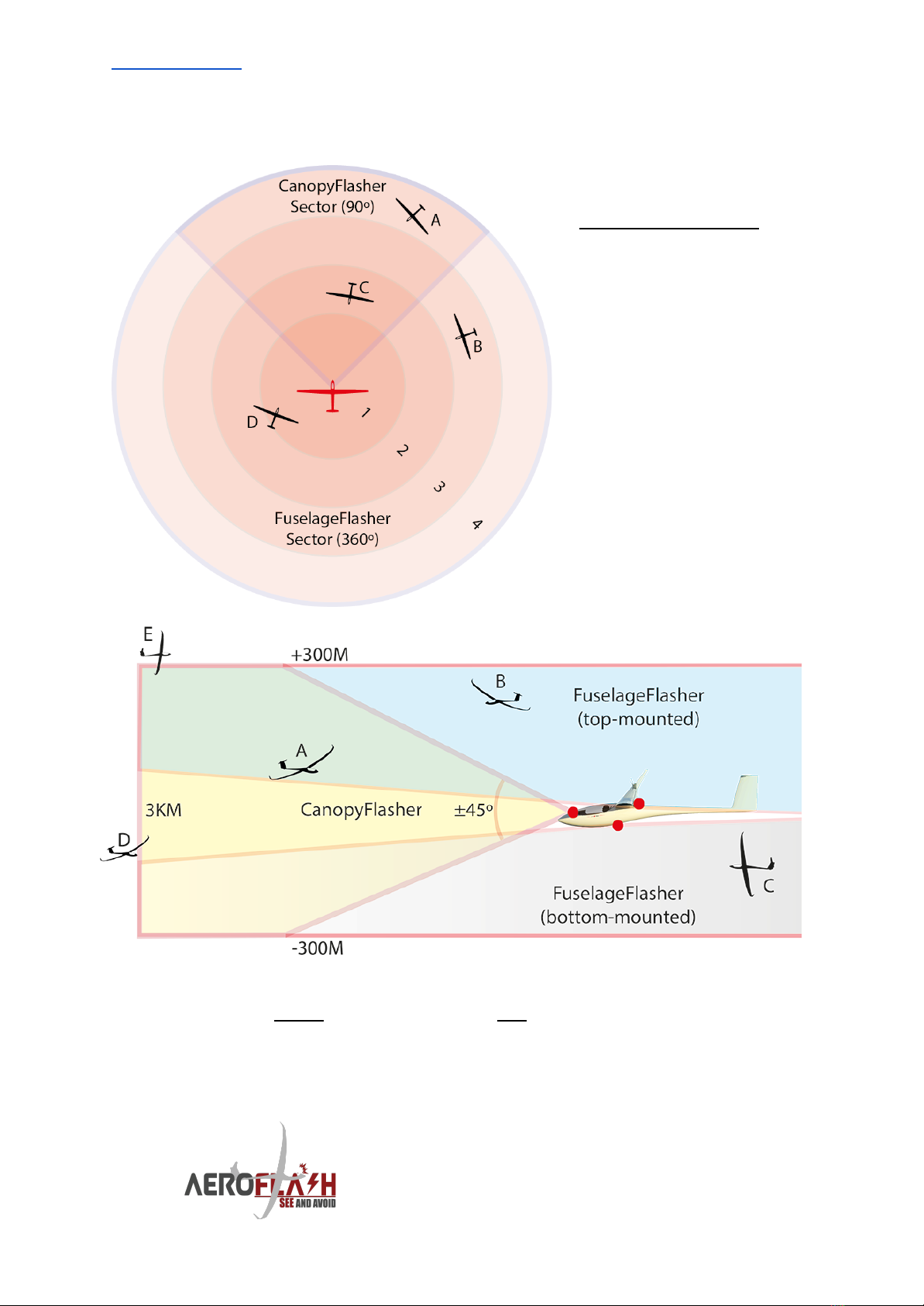
Example:
Glider A is flying in the CanopyFlasher Sector (90º x +/- 45º): both CF and FF are active.
Glider B and Ccannot see the CanopyFlasher: only the FuselageFlasher is active.
Glider D is more than 3km away: CanopyFlasher and FuselageFlasher are not yet
activated.
Glider E is flying within 3km and within the 30 degree CF-sector, but more than 300m
higher: CanopyFlasher and FuselageFlasher are not yet activated.
11
www.AeroFLASH.de “See and Avoid” starts with being SEEN Rev 2 - FEB 2022
Please always manually select ON-mode when visibility is
degraded or potentially dangerous situations may exist.
Examples of these are, but are not limited to: flying close to
cloud base, running under cloud streets, flying along
mountain ridges, white snowy mountainous areas, lot’s of VFR
traffic, competitions, circuit and landing, low standing sun,
close to sunset, etc. The extremely bright red LEDs really stand
out well in grayed out conditions. Never fully rely on
“AUTO-mode”: your Flarm reception may be poor, or
someone else’s Flarm signal may be weak! It may also
protect you from General Aviation traffic without Flarm!
3.1.5 Auto/ON mode logic - on ground
In AUTO-mode the CanopyFlasher and FuselageFlasher will not activate on
ground. They both will start flashing when the Flarm detects that the flight
has started, and if conflicting traffic is received, as mentioned in chapter
3.1.4. This logic will continue until shortly after coming to a full stop upon
landing.
ON-mode, before take-off
In ON-mode with Flarm connected, when on the ground before take-off,
the CanopyFlasher and FuselageFlasher will only flash for a short period of
20 seconds* and is then waiting in Standby-mode: ready for takeoff.This
is a protection to avoid an accidental overheating of the FuselageFlasher
without sufficient air cooling. This allows ample time to test the system and
show it off to your friends.
Now when you take-off, flashing will start immediately once the Flarm
detects that the aircraft is in flight.
Status LEDs alternating green and red indicate that the
system is in Standby-mode, on ground, when the switch is set
to ON. This only happens on ground, after the 20 second initial
testing mode. The system is then selected in Standby-mode,
and will start the continuous ON-mode flashing once the
Flarm detects that the aircraft is in flight. This is to prevent
overheating of the system during activation on ground
without airflow cooling.
*In ON-mode on ground, by resetting the switch from ON to
AUTO to ON, this protection logic will be overridden and no
12

www.AeroFLASH.de “See and Avoid” starts with being SEEN Rev 2 - FEB 2022
further overheating protection is available. This may be
necessary to operate the system without Flarm data (refer to
chapter 6.1 Troubleshooting). Limit the activation of the
FuselageFlasher on the ground for a maximum of 5 minutes!
Refer to chapter 3.6 Cooling requirements for more
information.
ON-mode, after landing
After landing in ON-mode with Flarm connected, the Nexus system will
automatically turn off the flashing logic approximately 30 seconds after the
flight has ended.
Do not rely on Flarm ending the flight status, and always
manually switch the system to AUTO or OFF after landing.
3.1.6 Hazard mode logic
When extremely hazardous conditions exist where (temporarily) maximum
visibility is demanded, Nexus can quickly be entered in a continuous
rapid-flashing operation. This generates the maximum available light
output and increases the chances of being seen. It basically simulates a
continuous Flarm level 3 (highest) warning, for a period of 5 minutes.
To enter Nexus in hazard mode, select the switch from AUTO to ON to
AUTO to ON to AUTO and once again to ON within 3 seconds (rapidly cycle
the mode switch 3 times to ON).
After 5 minutes Nexus will automatically revert into ON-mode and normal
flashing operation will return (steady green and red LED will show). If
required, the procedure can be repeated.
The CanopyFlasher status LEDs will confirm that the Nexus entered hazard
mode with the following blinking indication: GREEN -GREEN -RED -RED.
When in hazard mode, temperature protection is of course active.
When operating hazard mode on ground (for example after landing) with
Flarm connected, standby mode additionally protects your canopy and the
system from overheating.
No other Flarm warning inputs will be used for flashing logic during this
hazard mode operation.
13
www.AeroFLASH.de “See and Avoid” starts with being SEEN Rev 2 - FEB 2022
Switch on hazard mode in extremely crowded environments,
when landing, making a competition finish/low pass, or when
entering unexpected IMC or poor visibility.
Battery drain will be significantly increased due to the high
power consumption of this mode. Be aware of potential loss of
avionics or navigation with weaker or empty batteries. Avoid
using hazard mode with near to empty batteries.
Although temperature protection is available, avoid activating
hazard mode for prolonged times when on ground. The
CanopyFlasher and FuselageFlasher will become very hot
without air cooling. On ground, an overheat condition is very
likely to occur with high ambient temperatures. Standby
mode on ground is only available with Flarm connected!
3.2 Power consumption
Due to the smart technology and complex synchronized flash-sequencing
we incorporated in all AeroFlash products, power consumption is very
reasonable and should not be an obstacle to installing AeroFlash.
Typical power consumption in AUTO-mode after a 6-hour flight with
moderate traffic (multiple activations of a few minutes per hour) will result
in an average power consumption of only 300-1800mAh. Of course an exact
figure cannot be given.
System
situation &
setup
Standby
current
(not
flashing)
AUTO-mode, average consumption
per hour with moderate traffic*.
ON-mode,
per hour.
Nexus PRO +
CanopyFlasher +
FuselageFlasher
10mA
± 120 - 350mAh
450mAh
*These are theoretical values only and strongly depend on actual traffic conditions;
quantity and height/direction of traffic (when the CanopyFlasher does not need to
be activated it drains no power). Moderate traffic implies flashing activations
lasting several minutes, multiple (5 - 10) times per hour, with various Flarm
warnings.
AeroFlash can strongly recommend special AIRNERGY high
capacity LiNiMnCoO2 (NMC) batteries, which double capacity
versus LiFePO4 (LFP) for the same size and even lower weight!
14

www.AeroFLASH.de “See and Avoid” starts with being SEEN Rev 2 - FEB 2022
3.3 Power supply
All AeroFlash systems accept a power input of 10V to 20V DC. We designed
our system to be smart in an automatic power saving mode, or “always on”
in the ON-mode. AeroFlash should not be powered through the same
circuit breaker as the Flarm, as AeroFlash systems are rated significantly
higher.
There is NO fuse inside, nor included with the system. Suitable fuses or
circuit breakers are available from our dealers, or from AeroFlash directly.
The AeroFlash systems require a minimum thickness of 20AWG wire
(supplied as standard with Nexus PRO).
System setup
Circuit breaker requirement
Nexus PRO + CanopyFlasher +
FuselageFlasher
3A
We strongly advise to install an automatic circuit breaker that
can be tripped manually, rather than a fast blowing glass-fuse.
These automatic circuit breakers are available from AeroFlash
webshop or our dealers. Contact us for more information.
3.4 Dimensions and weights
Nexus PRO:
Dimensions LWH: 100 x 63 x 31mm (including mounting flanges).
Weight: ±190 grams.
CanopyFlasher:
Dimensions LWH: 90 x 64 x 23mm (±10%, length/height varies per glider
type).
Weight: ±100 grams with 50cm cable.
FuselageFlasher:
Dimensions LWH: 110 x 15 x 11mm (including mounting-foam tape).
Weight: ±15 grams without cable / ±95 grams with 4m cable.
3.5 Temperature specifications
All AeroFlash components are designed to operate in temperatures
ranging from -30 to +60ºC. These temperature limitations highly depend on
the actual ambient conditions. Generally with high-summer (>30°C)
temperatures some precautions must be observed:
15

www.AeroFLASH.de “See and Avoid” starts with being SEEN Rev 2 - FEB 2022
Maximum operating times at high ambient temperatures:
CanopyFlasher
FuselageFlasher
On ground
In flight
On ground
In flight
Max 10 minutes
50ºC OAT
Max 5 minutes!
60ºC OAT
(temperature
sensor prevents
overheating in
normal conditions)
(with
forward
canopy
airflow open)
(limited*
temperature
protection installed!)
(no additional
cooling
requirements)
*Refer to chapter 3.1.5 Auto/ON mode logic - on ground for
more information on the limited temperature protection.
3.6 Cooling requirements
In flight there are no special precautions that must be made for cooling of
the system. Multiple heat sinks, cooling slots and a temperature sensor are
built-in the CanopyFlasher to monitor the system and automatically shut it
down when an overheat condition is experienced (LED temperature of
70ºC). Ensure to never block the cooling slots.
Generally even in hot summer conditions, the airflow from the front of the
canopy is more than sufficient to cool the system and the system will not
even come close to the maximum operating temperature of 70ºC. These
protections are built-in solely to prevent aircraft- and system damage in
case of a failure of the electronics.
In high ambient temperatures (and strong sunlight), the
CanopyFlasher LEDs may become quite warm when operated
continuously on the ground, without cooling from the canopy
airflow ventilation. Do not fully rely on the temperature sensor
and avoid activating the system in “ON-mode” on the ground
for prolonged times.
The FuselageFlasher is cooled by airflow around the device. In flight there
are no further cooling requirements. On-ground observe the following
procedures:
There is a limited temperature protection built in the
FuselageFlasher! Do not activate the “ON-mode” on ground
for prolonged times (<5 minutes) when a FuselageFlasher is
16

www.AeroFLASH.de “See and Avoid” starts with being SEEN Rev 2 - FEB 2022
installed. Serious damage to the flasher, as well as to the
fuselage (overheating) may occur due to the lack of
air-cooling, especially in strong sunlight and high ambient
temperatures!
Always switch off the “ON-mode” after landing by turning the
switch back to AUTO! Refer to chapter 3.1.5 Auto/ON mode
logic - on ground for more information on the limited
temperature protection.
Please always use a canopy cover whenever the glider is not
in use, and switch off the power supply to the system. This will
benefit the life-time of all the components due to less
exposure to heat and UV light.
3.7 Humidity
Nexus PRO, the CanopyFlasher are designed to operate in humidity
ranging from 0 to 95%.
The FuselageFlasher is waterproof. Please refer to the specific installation
instructions in chapter 4.8 for more details.
3.8 Mounting requirements
Nexus PRO may be mounted with up to 4 screws, or by using the supplied
3M “Dual Lock” super strong double sided adhesive tape and some cable
ties. In any case Nexus PRO should be mounted in accordance with the
installation requirements as per (a.o.) CS-SC036a and CS-SC402b.
The CanopyFlasher comes prepared with super strong black 3M double
sided adhesive foam tape. It is strongly recommended to use this black
tape as it blocks out any reflections that may appear in the canopy when
the flasher is activated. This 3M tape is safe to use on plexiglass.
4. Installation instructions and examples
The installation of an AeroFlash system must comply with EASA
regulations as per Standard Change CS-SC036a “INSTALLATION OF
VISUAL AWARENESS LIGHTS”:click here for the link to the EASA
document.
17

www.AeroFLASH.de “See and Avoid” starts with being SEEN Rev 2 - FEB 2022
4.1 Scope of delivery
1x Nexus PRO device.
1x CanopyFlasher with 3M double sided adhesive foam tape pre-applied
and cable set ***.
1x FuselageFlasher with 3M double sided adhesive foam tape pre-applied,
with 4 meter pre-attached AWG20 wiring (3 wires: red, red, black) - other
lengths available on request.
1x Nexus PRO cable set with 8-pin pluggable screw-terminal connector
pre-attached, with OFF/Auto/ON switch connected (total length 70cm
standard, other lengths available on request).
1x RJ12 - RJ12 1:1 cable 10cm - for connection between Nexus and splitter.
1x RJ12 - RJ12 1:1 cable 50cm - for connection Nexus-Flarm.
1x RJ12 - RJ45 1:1 cable 50cm - for connection Nexus-Flarm.
1x 3-Way RJ12 splitter.
1x Mini-USB to USB-A cable 150cm, for firmware updates.
1x 15cm 3M Dual Lock adhesive tape for mounting of Nexus PRO.
1x Vinyl sticker template for aligning the CanopyFlasher during installation.
1x OFF/Auto/ON switch marking/label.
*** The cable set version depends on the canopy opening direction:
- Vertical opening canopies receive a DB9 connector set. If required
you will receive an extension cable.
- Side opening canopies receive a matching 7-pin
panel-cover-mounted CanopyConnector/PanelContact set with
various mounting supports, depending on the chosen option:
general or Schempp-Hirth style.
NOT included, optionally available and may be required for the
installation:
Fuse/circuit breaker, 3A - available from us separately.
Silicone sealant/kit (for weather-proofing the FuselageFlasher).
Additional power cable. Crimp or soldering tools. Cable ties, cable clips.
4.2 Installation of the Nexus PRO unit
Find a suitable location for the Nexus PRO unit. It may be required to make
some brackets and use the mounting flanges to mount it with two or four
screws. Avoid over-tightening of screws on the plastic flanges, as the plastic
may break! It may also be possible to use some cable ties to mount the
Nexus to another device, or use a piece of the 3M Dual Lock adhesive tape
that we included.
18

www.AeroFLASH.de “See and Avoid” starts with being SEEN Rev 2 - FEB 2022
Insert the green 8-pin pluggable screw-terminal connector into the Nexus
PRO. On the other side of the Nexus you will find the DB9 connector. This
connector is used for the CanopyFlasher.
You will also find a pre-installed Red and black wire pair. Use the Red
(positive, attached to the switch) and black (ground) wire to power the
Nexus PRO. Observe the maximum input voltage of 20V DC and the
polarity of the wiring.
Install a fuse or circuit breaker. Observe the tripping current as
per chapter 3.3, and connect these to the glider’s power
network.
On the cable set you will also find the OFF/Auto/ON switch.
More about this later.
4.3 Connection to a Flarm
In normal installations the Nexus is installed to the Display Port of a Flarm.
Additionally it may be installed to the Power/Data port of a Flarm. Caution
must be used to select in this case the supplied RJ45 to RJ12 cable.
Inserting a RJ12 (6-pin) connector in a RJ45 (8-pin) socket may work fine,
but could result in a poorly fitted connector with the potential of damage
to both devices.
Nexus is able to automatically capture the required baud rate from your
Flarm. Supported baud-rates are 9600, 19200, 38400 and 57600 bps. You
can use the FlarmTool to change your Flarm’s baud rate if this is not set to
one of these figures. You can also configure this in your Flarm by SD card,
or modify this in the LX-flight computer.
If for any reason a Flarm Display Port is not available, it may be
connected to a “USER port” that offers NMEA output. At least
“PFLAU” sentences must be transmitted. Special caution must
be given to the pinout of these sort of “USER ports”, as these
may not be IGC-standard! Please refer to chapter 3.1.1 RJ12
input port for more information.
4.4 Mounting the CanopyFlasher
Mark the centerline of the canopy with a piece of white
PVC tape. Please be cautious to use the yaw string as
centerline reference, as often these are not placed in the
exact center! Using the supplied vinyl grid sticker may
19

www.AeroFLASH.de “See and Avoid” starts with being SEEN Rev 2 - FEB 2022
make it easier to align the CanopyFlasher so it’s perfectly straight. It may be
very difficult to see the alignment once you try to stick it to the canopy
from the inside.
Before permanently mounting the CanopyFlasher, check if
the selected location does not intervene with the canopy
ventilation mechanism!
After marking the correct position, it may be easiest to remove the canopy
and place it upside down on a soft/safe location.
Clean the surface of the canopy with a non-aggressive cleaning agent to
remove dirt and grease, to ensure the adhesive tape sticks well. Normally
water and a bit of soap is fine.
The CanopyFlasher is pre-applied with black 3M VHB double sided
adhesive foam tape. It is strongly recommended to use this black tape as it
blocks out any reflections
that may appear in the
canopy when the flasher is
activated. This 3M tape is
safe to use on plexiglass
canopies.
Remove the film and
carefully stick the
CanopyFlasher against the
canopy. Be careful not to
apply too much force to
the canopy, but make sure
the tape is attached well in
all corners. If there is a
small air bubble between
the canopy and the tape,
don’t attempt to remove
the CanopyFlasher. Most
likely the bubble will
disappear in a couple of
days or with some warmth
from the sun.
The 3M VHB double sided adhesive foam tape is best applied
at temperatures above 15ºC.
20
This manual suits for next models
3
Table of contents
Other AeroFlash Lighting Equipment manuals


