AEROPRAKT AEROPRAKT-32 User manual

Aeroprakt Ltd.
24, Polevaya str., Kiev, Ukraine
Tel: 0038 044 496-77-21
Fax: 0038 044 496-77-31
e-mail: [email protected].ua
www.aeroprakt.kiev.ua
1
AEROPRAKT-A32
Airplane Maintenance Manual
A32-002-AMM
Airplane Model: AEROPRAKT-32 (A-32)
Airplane Registration Number:
Airplane Serial Number: 002
Date of issue: 07.04.2015
Approved by: Yuriy Yakovlyev
Position: Chief designer
Date of approval: 07.04.2015
This manual must be carried in the airplane at all times.
This airplane is to be serviced and maintained in compliance with information and instructions
contained herein.

AEROPRAKT-32 Airplane Maintenance Manual A32-002-AMM
2
RECORD OF REVISIONS
No part of this manual may be reproduced or changed in any manner without a written
consent of the Manufacturer.
Any revision of the present manual must be recorded by the Manual holder in the following
table according to information from the Manufacturer.
New or amended text in the revised pages must be marked by a black vertical line on the
left hand margin. The Revision No. and the date must be shown on the bottom left hand
side of the page.
Rev. No.
Notice/Bulletin No.
Affected Pages
Date Issued
Date Inserted
Signature

AEROPRAKT-32 Airplane Maintenance Manual A32-002-AMM
3
Contents
1General.........................................................................................................................4
1.1 SOURCES TO PURCHASE PARTS ..............................................................................................................................5
1.2 EQUIPMENT LIST....................................................................................................................................................5
1.3 DISPOSABLE REPLACEMENT PARTS........................................................................................................................5
1.4 ENGINE SPECIFICATIONS........................................................................................................................................6
1.5 WEIGHT AND BALANCE INFORMATION ..................................................................................................................7
1.6 TIRE INFLATION PRESSURE ....................................................................................................................................7
1.7 APPROVED FUEL,OILS AND CAPACITIES ................................................................................................................8
1.8 RECOMMENDED FASTENER TORQUE VALUES.........................................................................................................8
1.9 GENERAL SAFETY INFORMATION...........................................................................................................................9
1.10 REPORTING MAINTENANCE,SERVICE,AND SAFETY DIFFICULTIES .........................................................................9
2Inspections ................................................................................................................10
3Structures ..................................................................................................................13
4Landing gear..............................................................................................................17
5Brake system.............................................................................................................21
6Engine and its control system..................................................................................25
7Cooling system..........................................................................................................29
8Lubrication system....................................................................................................30
9Fuel system................................................................................................................31
10 Exhaust system.........................................................................................................33
11 Propeller.....................................................................................................................34
12 Airplane control system............................................................................................35
13 Electrical system.......................................................................................................40
14 Cockpit heating system ............................................................................................49
15 Instruments and Avionics.........................................................................................50
16 Full and static pressure system...............................................................................52
17 Pilot seats and harness belts...................................................................................54
18 Cockpit doors ............................................................................................................55
19 Recovery system.......................................................................................................56
20 Structural repair.........................................................................................................57
20.1 GENERAL.............................................................................................................................................................57
20.2 FUSELAGE GLAZING REPAIR ................................................................................................................................57
20.3 FABRIC COVERING REPAIR...................................................................................................................................58
20.4 COMPOSITE PARTS’REPAIR .................................................................................................................................59
20.5 RESTORING OF DAMAGED PAINT/COATING ..........................................................................................................61
21 Feedback Form..........................................................................................................62

AEROPRAKT-32 Airplane Maintenance Manual A32-002-AMM
4
1 General
NOTE: This manual is subject to change by the notifications or safety bulletins published
at the official website of Aeroprakt company http://www.aeroprakt.kiev.ua.
This manual describes the procedures of proper aircraft handling and servicing
recommended by the aircraft manufacturer. It also specifies the requirements to inspection
and maintenance that are required for keeping the flight performance and reliability at a
level of a new airplane. It is recommended to adhere to the scheduled periods of
greasing/lubrication and preventive maintenance taking into account the climate and
operating conditions.
Each of the inspection or service/maintenance action outlined in this manual specifies:
recommended special tools (if any) to accomplish the task,
the parts needed to perform the task,
type of maintenance, for example, line, heavy, or overhaul,
the level of certification needed to accomplish the task, for example, owner, A&P,
LSA repairman with inspection (or maintenance) rating, and repair station,
detailed instructions and diagrams as needed to perform the task,
method to test/inspect to verify the task was accomplished properly.
The types of the maintenance (TM) tasks specified in this manual are marked with the
following one-letter abbreviation and are defined as follows:
Line maintenance (L)any repair, maintenance, scheduled checks, servicing,
inspections, or alterations not considered heavy maintenance that is approved by the
manufacturer and is specified in this maintenance manual.
Heavy maintenance (H) any maintenance, inspection, repair, or alteration which
manufacturer has designated that requires specialized training, equipment, or facilities.
Overhaul (O) maintenance, inspection, repair, or alterations that are only to be
accomplished by the manufacturer or a facility approved by the original manufacturer of
the product.
The levels of certification (LC) needed to accomplish the maintenance tasks specified in
this manual are marked with the following three-letter abbreviation and are defined as
follows:
OWN (owner) items that can be expected to be completed by a responsible owner who
holds a pilot certificate but who has not received any specific authorized training.
LRI (LSA repairman inspection) items that can be expected to be completed on an
ELSA by a responsible owner, which holds an FAA repairman certificate (light sport
aircraft), with an inspection rating or equivalent.
LRM (LSA repairman maintenance) items that can be expected to be completed on a
SLSA by a responsible individual, which holds a FAA repairman certificate (light sport
aircraft), with a maintenance rating or equivalent.
A&P (airframe and powerplant mechanic) items that can be expected to be completed
by a responsible individual who holds a mechanic certificate with airframe or powerplant
ratings, or both, or equivalent.
TSP (task specific) items that can be expected to be completed by a responsible
individual who holds either a mechanic certificate or a repairman certificate and has
received task specific training to perform the task.

AEROPRAKT-32 Airplane Maintenance Manual A32-002-AMM
5
1.1 Sources to purchase parts
For purchasing any parts or spares for this airplane contact your local dealer/distributor or
address the aircraft Manufacturer: Aeroprakt Ltd., Polyova str. 24, 03056, Kyiv, UKRAINE,
1.2 Equipment list
This aircraft has the following equipment:
Flight instruments:
oBK-3 airspeed indicator
oBG-3E altimeter
oDynon SkyView system
Engine instruments:
oDynon SkyView system
otwo VAZ-2104 fuel level indicators
Radio equipment:
oDynon radio SV COM 425
oDynon intercom SV 2S
Miscellaneous equipment
oStrobe & navigation lights
oLanding light
1.3 Disposable replacement parts
The manual (see Sections 3 through to 16) contains the check lists with information about
check periods, recommended change out (RCO) times as well as references to inspection
and servicing/maintenance instructions for the airplane components and systems.
Before expiration of the recommended change out time of separate airplane parts or when
it is not specified their operation shall be performed on condition (OC). Such parts must be
inspected and replaced, if necessary, before expiration of the RCO (if specified).
If inspections and checks arouse any issues not covered in this manual contact the
Manufacturer for additional information.
Upon detecting corrosion on airplane structural elements contact the Manufacturer for the
required technical support. In this case further operation of the airplane may be
dangerous!

AEROPRAKT-32 Airplane Maintenance Manual A32-002-AMM
6
1.4 Engine specifications
WARNING! On all issues of engine operation see Rotax engine Operator's Manual.
Follow its instructions to ensure safe and efficient operation of the engine.
Engine data and operational limitations are given in the table below:
Engine manufacturer:
BOMBARDIER-Rotax-GmbH (Austria)
Engine model:
Rotax-912UL
Rotax-912ULS
Engine type:
Flat-four, four-stroke
Maximum takeoff power:
80 h.p.
100 h.p.
Time limit at full power:
5 min (5800 rpm)
Max. revolutions (no time limit)
5500 rpm
Min. revolutions at idle
1400 rpm
Maximum coolant temperature
at pick-up point:
Oil temperature, normal
minimum
maximum
90--
90--
Exhaust gas temperature:
- maximum at takeoff
- maximum
- normal
Oil pressure, normal
minimum
maximum
2,0-5,0 bar (29-73 psi) (above 3500 RPM)
0,8 bar (12 psi) (below 3500 RPM)
7 bar (100 psi) (at cold start, allowed for a short time)
Fuel pressure, normal
maximum
0,15-0,4 bar (2,2-5,8 psi)
0,4 bar (5,8 psi)
Ambient air temperature range
from -

AEROPRAKT-32 Airplane Maintenance Manual A32-002-AMM
7
1.5 Weight and balance information
The airplane CG position must be between 1.53 m and 1.78 m or between 19% and 37%
of the wing MAC (mean aerodynamic chord) see Fig. 1.
Fig. 1 CG location of the empty airplane, pilots, fuel and baggage
Compute the airplane C.G. position using the example in the table below (for the maximum
take-off weight):
Item
Weight, kg
×
Arm, m
=
Moment, kg·m
Empty aircraft
332.5
1.645
=
547.0
180.0
1.663
=
299.3
Baggage
22.7
2.320
=
52.7
Full fuel (90 l, 0.72 kg/l)
64.8
1.960
=
127.0
Total:
600.0
1026.0
XCG = Total moment / Total weight
=
1.710
m
1.6 Tire inflation pressure
Normal inflation pressure for both main and nose wheels is 1.6 kg/cm2(22.8 psi).

AEROPRAKT-32 Airplane Maintenance Manual A32-002-AMM
8
1.7 Approved fuel, oils and capacities
WARNING! On all issues of engine operation see Rotax engine Operator's Manual.
Follow its instructions to ensure safe and efficient operation of the engine.
Fuel
Approved grade: unleaded MOGAS min. RON 95 or AVGAS 100LL
Maximum capacity of the fuel tanks45 = 90 liters
approx. 6 liters per tank
Unusable fuel: approx. 0.5 liter
Oil
Approved grade: any automotive oil of API classification or higher
Oil tank capacity: 3 liters (NOTE: check correct oil level in the tank using the oil probe.)
Coolant
Approved grade: TELKO Polar Premium Long Life Antifreeze
Quantity: 3 liters (NOTE: check the correct level using the overflow bottle marks.)
Braking fluid
Approved grade: Mobil ATF 220
Quantity: 0.2 liter (NOTE: check the correct level using the overflow bottle marks.)
1.8 Recommended fastener torque values
In A-32 all fasteners in front of the firewall and in the electrical system is metric and rear of
the firewall inch. The torque of the screws and nuts (unless specified otherwise) are as
follows:
1. For the static joints joints with spacing inserts (spacers, spherical bearings, etc.)
according to the table:
Metric fasteners
Inch fasteners
Torque,
М5
10-32
6 (4.4)
М6
1/4
10 (7.4)
М8
5/16
15 (11.0)
М10
3/8
25 (18.4)
2. For the movable joints where bolts serve as hinge axle the nuts tightening must be
done only to remove the axial play (gap) while preserving the rotational freedom in
the joint.
WARNING! All bolts, nuts (except for self-locking ones), pins, turnbuckles must be locked
reliably.

AEROPRAKT-32 Airplane Maintenance Manual A32-002-AMM
9
1.9 General safety information
Aircraft owner/operator responsibilities:
Each owner/operator of the Aeroprakt LSA must read and comply with the maintenance
and continued airworthiness information and instructions provided by the Manufacturer.
Each owner/operator of the Aeroprakt LSA is responsible for providing the Manufacturer
with current contact information where the Manufacturer may send the owner/operator
supplemental notification bulletins.
The owner/operator of the Aeroprakt LSA is responsible for notifying the Manufacturer of
any safety of flight issue or significant service difficulty upon discovery.
The owner/operator of the Aeroprakt LSA is responsible for complying with all notices of
corrective action issued by the Manufacturer and for complying with all applicable aviation
authority regulations in regard to maintaining the airworthiness of the LSA.
The owner/operator of the Aeroprakt LSA must ensure that any needed corrective action
be completed as specified in a notice, or by the next scheduled annual inspection.
Should the owner/operator of the Aeroprakt LSA not comply with any mandatory service
requirement, the LSA shall be considered not in compliance with applicable ASTM
standards and may be subject to regulatory action by the presiding aviation authority.
1.10 Reporting maintenance, service, and safety difficulties
In case of encountering any maintenance or service or safety difficulties not covered by
this Manual report about it to the aircraft Manufacturer by e-mail or by fax using the
Feedback Form (see Appendix A). If necessary enclose sketches or photos showing the
problem items in sufficient detail.

AEROPRAKT-32 Airplane Maintenance Manual A32-002-AMM
10
2 Inspections
This section contains the instructions and checklist for inspection and servicing for the
completion of periodic and annual condition/100-h inspections with references to the
sections containing detailed instructions for the inspection/servicing action.
Inspection/Servicing action and its interval in hours
50
100
200
500
1000
2000
Structures (section 3)
Inspect fuselage for damage (fatigue cracks, loose rivets, etc.)
X
Inspect fuselage glazing for damage (silvering, cracks, etc.)
X
Inspect wings for damage (fatigue cracks, loose rivets, torn fabric covering, etc.)
X
Inspect wing attachment points for play
X
Remove the wings and inspect its spherical bearings for play and hinge brackets for
cracks
X
Inspect the wing struts for fatigue cracks, deformation and loose rivets
X
Inspect the sealing fabric tape of the wing strut fairings
X
X
Inspect the all-flying horizontal tail (AFHT) for fatigue cracks, deformation, loose
rivets and play in joints
X
Check the AFHT attachment bolts/nuts torque and locking
X
Inspect the tail wheel for damage and play
X
Check the tail wheel attachment bolt/nut torque and locking
X
Inspect engine cowlings for damage (cracks, ruptures, damaged paint, etc.)
X
Landing gear (section 4)
Inspect the nose leg for fatigue cracks, deformation and play
X
Check the nose leg bellcrank bolt/nut torque and locking
X
Check the shock absorber condition
X
Inspect the MLG springs and attachment beam for fatigue cracks1, deformation and
play
X
Check the MLG spring attachment bolts/nuts torque and locking
X
Inspect the wheel tires for cracks, cuts and wear.
X
Inspect the wheel fairings for cracks, ruptures and damaged paint
X
Check the torque and locking of the fairings attachment bolts/nuts
X
Inspect the mud-screens for fatigue cracks and deformation2
X
Check the torque and locking of the mud-screen attachment bolts/nuts2
X
Inspect the skis for damage3
X
Check the torque and locking of the ski attachment bolts/nuts3
X
Brake system (section 5)
Inspect expansion tank for leaks, cracks, secure attachment. Check fluid level.
X
Inspect the master cylinder for leaks of braking fluid
X
Inspect the parking brake valve for leaks of the braking fluid
X
Inspect the brake unit for the leaks of the braking fluid
X
Measure the brake disks' wear
X
Inspect the brake system tubing and joints for leaks and damage
X
Engine and its control system (section 6)
Inspect the engine mount for fatigue cracks and deformation
X
1
After 5000 landings the MLG springs must be removed and inspected carefully for fatigue cracks
2
For an aircraft version on wheels with mud-screens
3
For an aircraft version on skis

AEROPRAKT-32 Airplane Maintenance Manual A32-002-AMM
11
Inspection/Servicing action and its interval in hours
50
100
200
500
1000
2000
Check the torque of the engine mount attachment bolts
X
Inspect the rubber mounts for damage (deep cracks, etc.)
X
Check the intake airbox function, condition and attachment4
X
Inspect the throttle and choke cables and cable sheath for wear, damage, kinks
X
Check the torque of the throttle lever bolt (axle)
X
Cooling system (section 7)
Check the radiator attachment grommets condition
X
Inspect the overflow tank for leaks of coolant, cracks; check coolant level
X
Inspect lines for leaks, damage (chaffing, cracks), loose joints
X
Lubrication system (section 8)
Inspect the oil tank plug for oil leaks; verify vent line is intact and secured
X
Inspect lines for leaks and damage (chaffing, cracks), loose joints
X
Fuel system (section 9)
Remove fuel tanks and inspect them for fuel leaks and damage
X
Inspect the shut-off and drain fuel valves for leaks of fuel
X
Check condition and replace fuel filter (if necessary)
X
Inspect fuel lines for leaks, damage (chaffing, cracks), loose joints
X
Check condition and replace fuel lines (if necessary)
X
Exhaust system (section 10)
Inspect exhaust pipes and muffler for cracks
X
Verify attachment springs are intact
X
Propeller (section 11)
Inspect propeller hub for fatigue cracks; check pitch angles
X
Check torque and locking of the propeller bolts/nuts
X
Check torque of the spinner bolts
X
Airplane control system (section 12)
Inspect control surfaces for fatigue cracks, deformation, loose rivets, torn fabric
X
Check the play in the hinges of control surfaces/linkages
X
Check tightness/locking of the nuts of control surfaces/linkages
X
Check tightness/locking of the nuts and play in hinges of control rods/shafts
X
Inspect AFHT control cable for wear, check cable tension
X
Inspect flaperons control cable for wear, check cable tension
X
Inspect rudder control cables for wear, check cable tension
X
Extend flaps and inspect flap extension (play in hinges, nuts tightness/locking)
X
Grease the slide bearings of all control surfaces/linkages (where necessary)
X
Inspect rudder pedals for fatigue cracks and deformation
X
Check condition of the control cable pulleys and fairleads
X
Check trim tab attachment bolts/nuts for corrosion, replace if necessary
X
Inspect the trim tab control cables and sheath for damage (wear, kinks, etc.)
X
Electrical system (section 13)
Verify battery charges/discharges properly, otherwise replace
X
Clean starter terminals and starter relay connector of corrosion, if any
X
Verify starter relay and cables are connected and attached reliably
X
Verify power cables have good contact with battery, starter and ground
X
4
For an aircraft version equipped with intake airbox

AEROPRAKT-32 Airplane Maintenance Manual A32-002-AMM
12
Inspection/Servicing action and its interval in hours
50
100
200
500
1000
2000
Clean rectifier-regulator and condenser terminals/connectors of corrosion, if any
X
Check condition of electric switches and warning lights
X
Clean fuse block terminals of corrosion, if any. Check fuses
X
Verify correct function of the fuel level sensors/indicators (check readings)
X
Check landing light function and attaching nut torque
X
Clean engine sensors' terminals and connectors of corrosion, if any
X
Inspect electrical harness for damage (chaffing, broken wires, bad insulation)
X
Cockpit heating system(section 14)
Inspect warm air shutter and its hinges for play/wearing. Repair or replace if
necessary
X
Check condition and operation of the warm air shutter actuator. Replace if necessary
X
Instruments and Avionics (section 15)
Check condition of the switches and lights. Replace defective ones, if any
X
Check operation of the instruments and avionics. Replace defective ones, if any
X
Check condition of the full and static pressure system
X
Pilot seats and harness belts (section 16)
Inspect the seats framework for the fatigue cracks and loose rivets
X
Inspect the seat cushions upholstery for damage
X
properly
X
Cockpit doors (section 17)
Inspect door glass, framework and sealing for damage
X
Verify the gas struts function properly
X
Recovery system (section 19)
Check attachment of the suspension cables to fuselage and parachute lanyard
X
AEROPRAKT-32 Airplane Maintenance Manual A32-002-AMM
13
3 Structures
The airframe of A-32 airplane includes the following parts: fuselage with polycarbonate glass
windscreen, wings, wing struts, all-flying horizontal tail (AFHT), vertical tail unit, wing fillets,
strut fairings and engine cowling. Fuselage with fin and wing struts are made of aluminum
alloys. Wing framework including leading edge section and top skin are all-metal and bottom
skin is fabric. Framework of flaperons, elevator and AFHT is all-metal, their rear skin (aft of
spar) is fabric. The rear fuselage skin panels (top and two side ones) include windows of
PVC glass. The aft wing fillets and engine cowling are made of fiberglass.
When servicing the airplane a special care shall be taken to protect the airframe from
corrosion and to protection of the paint coating. Protection of the airframe parts from
corrosion consists mainly of keeping the protective coatings intact. Care of the fabric skin
consists mainly of care of its paint coating. Correct care of the paint coating is one of the
conditions of preserving the airplane strength and aerodynamic characteristics. To keep
the paint coating of the airplane in good condition the dust and moisture must be removed
in time, the paint must be protected from scratches, and spilling oil products, solvents,
alkalis and acids on paint must be avoided.
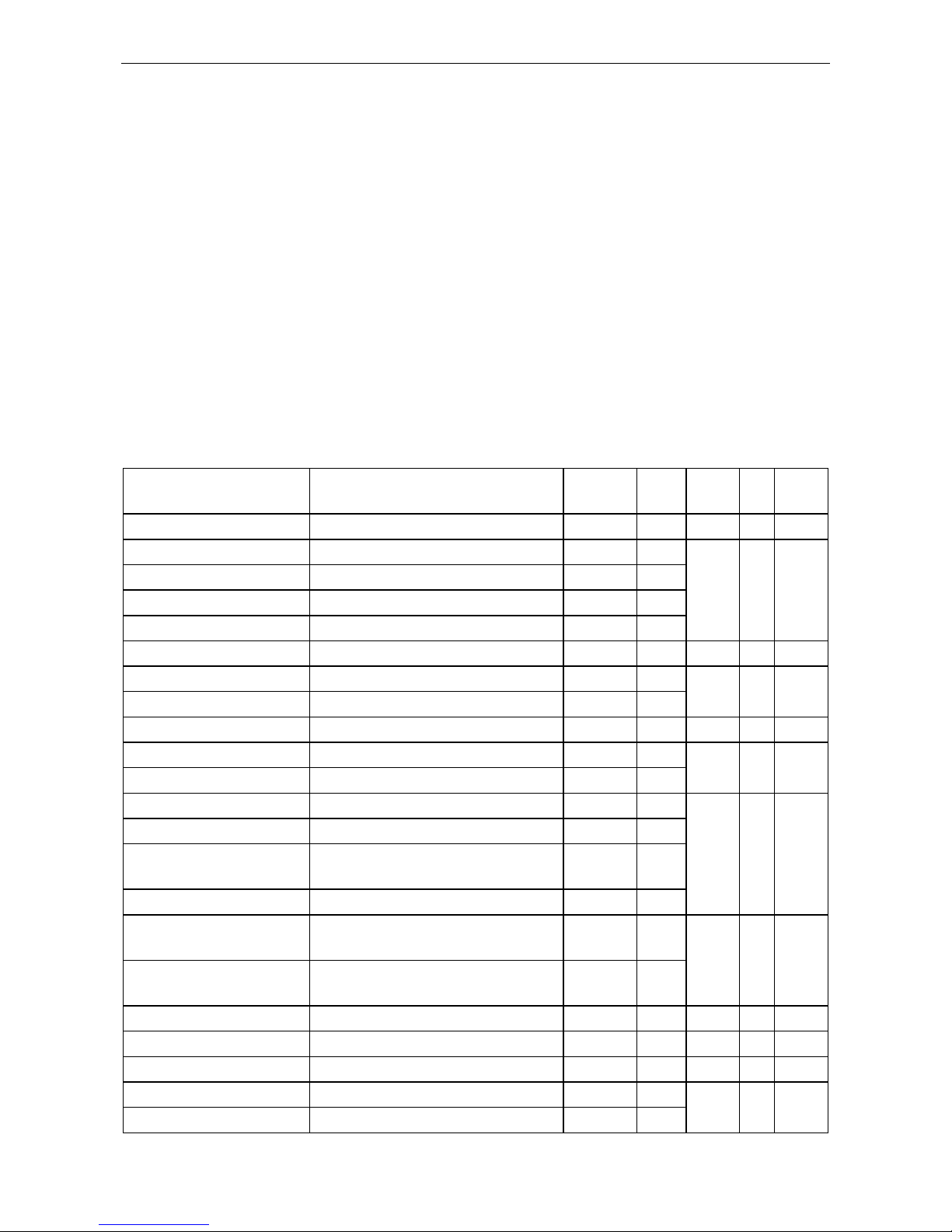
INSPECTION CHART
Part No.
Description
Interval
RCO
Instr.
No.
TM
LC
A32-0-530000-00-000
Fuselage
100 h
OC
3.1
L
LRI
A32-0-561000-01-000
Windscreen glass
100 h
OC
3.2
L
OWN
A32-0-530000-12-000
Rear fuselage skin panel, top
100 h
OC
A32-0-530000-08-001
Rear fuselage skin panel, right
100 h
OC
A32-0-530000-08-002
Rear fuselage skin panel, left
100 h
OC
A32-0-572000-00-000
Wing
500 h
OC
3.3
L
OWN
A32-0-531200-00-001
Aft wing fillet, right
200 h
OC
3.10
LRI
A32-0-531200-00-002
Aft wing fillet, left
200 h
OC
COM-5T
Spherical bearings, 4 pcs.
2000 h
OC
3.4
L
LRI
A32-0-579000-00-001
Wing strut, right
500 h
OC
3.5
L
LRI
A32-0-579000-00-002
Wing strut, left
500 h
OC
A32-0-579120-00-001
Wings strut fairing, top, right
200 h
OC
3.6
L
LRI
A32-0-579120-00-002
Wings strut fairing, top, left
200 h
OC
A32-0-579110-00-001
Wings strut fairing, bottom,
right
200 h
OC
A32-0-579110-00-002
Wings strut fairing, bottom, left
200 h
OC
AN 175-16
Wing front attachment bolts, 2
pcs.
100 h
OC
1.8
L
OWN
AN 175-12
Wing aft attachment bolts, 2
pcs.
100 h
OC
-0-530000-63-000
Tail skid
100 h
OC
3.8
L
LRI
AN 3-6
Top tail skid bolt, 2 pcs.
100 h
OC
1.8
L
OWN
AN 4-7
Bottom tail skid bolt, 2 pcs.
100 h
OC
1.8
L
OWN
A32-3-711020-00-000
Engine cowling panel, top
100 h
OC
3.9
L
LRI
A32-3-711010-00-000
Engine cowling panel, bottom
100 h
OC

AEROPRAKT-32 Airplane Maintenance Manual A32-002-AMM
14
Instructions:
1.1 Remove the engine cowling, doors, wing strut fairings (undo the screws fixing the
fairings and 'slide' them along the strut), pilot seats, and rugs. Inspect the fuselage
for cracks and deformation, paying special attention to primary structural elements,
areas of their connection and rivet joints (frames No. 1, 4, 5, 6, longitudinal,
transverse and vertical beams of the cockpit, undercarriage beam, fuselage tubes,
tail boom and fin skin).
Inspection for fatigue cracks. Use torch or any other suitable source of light. When
detecting very thin cracks remove the paint in the area of the suspected crack for a
closer flaw detection. If possible apply load in this area in a manner that will 'open up'
the crack. If the closer inspection confirmed the crack existence contact the
manufacturer for required technical support. If the suspected crack was not detected
repaint this area.
Inspection for loose rivets. When inspecting rivet joints look at the area around
river heads. The paint around the rivet heads must have no cracks or black stains
that indicate on loose and corroded rivet joint. When detecting such flaws contact the
manufacturer for the required technical support.
If no flaws were detected reinstall everything in the reversed order. Apply Loctite 222
on the thread of the attachment screws of the wing strut fairings before reinstalling
them.
Recommended special tools: magnifying glass, electric torch.
Necessary parts/materials: paint, Loctite 222.
1.2 Inspect the glass for 'silvering' (micro cracks) and cracks in the attachment areas.
When detecting a crack shorter than 50 mm (2 in) carefully cut a hole at its end with
a 3 mm (0.12 in) drill to stop the crack propagation. If the crack is longer than
50 mm (2 in) the glass must be replaced. Contact the manufacturer for glass
replacement instructions.
WARNING! The glazing material is not resistant to fuels, oils and solvents. Spilling
those liquids on glazing may cause its dimness and cracking.
Recommended special tools: electric drill, 3 mm drill.
Necessary parts/materials: none.
1.3 Drain fuel from the fuel tanks. Remove the wing strut fairings and fuel tanks. Inspect
the wing for fatigue cracks, deformation and loose rivets as described in 1.1 (2nd and
3rd paragraph). Pay special attention to the strut-to-wing attachment points, rivet
joints of the wing leading edge section and top skin.
Inspect the fabric skin for damage and detachment from the wing framework. It is
allowed to repair small cuts/ruptures (shorter 50 mm or 2 in) covering them with
ORACAL permanent sticking film. Upon detecting bigger damages and delaminating
of the fabric skin from the framework contact manufacturer for the required technical
support.
Verify that there is no play in attachment points of the wing and strut by holding the
wingtip gently and moving it up and down with an amplitude of 300 mm (1 ft). The
movement in the attachment points due to loose joint (play) is not allowed. When
detecting insignificant radial play (less than 0.2 mm or 0.01 in) in the strut attachment
points it must be eliminated by tightening its bolt joint. In case if the play is more than
0.2 mm (0.01 in) contact the manufacturer for the required technical support.

AEROPRAKT-32 Airplane Maintenance Manual A32-002-AMM
15
In case if no defects are found re-assemble everything in the reversed order. Before
re-installing the screws attaching the fuel tanks and strut fairings apply Loctite 222 on
the thread.
Recommended special tools: magnifying glass, electric torch.
Necessary parts/materials: ORACAL permanent sticking film, Loctite 222.
1.4 Detach the wings by doing the following:
- detach the doors;
- drain fuel from the fuel tanks;
- disconnect the fuel lines from the fuel valves, close the valves, plug the fuel lines
and pull them out of cockpit through the rubber sealing rings in fuselage beams;
CAUTION! Be careful while working with the fuel system, the fuel remaining in the
fuel lines is highly fire-hazardous and when spilled on the cockpit glass may cause
glass dimness and cracking.
- disconnect the electric connectors of the navigation lights and fuel level probes at
wing root and take the cables out of fuselage;
- detach the strut fairings (undo the screws attaching the fairings and slide fairings
along the struts);
- detach the Cardan rings from the flaperon shafts by removing the vertical bolts;
- remove the split pins and undo the nuts from wing and strut attachment points;
- while holding the wing by the tip and strut carefully take out the strut attachment
bolts and remove the struts;
- while holding the wing by the tip and at the root take out the wing attachment bolts
and slowly move the wing away from fuselage carefully pulling the navigation light
from the wing fillets;
Inspect the wing and strut attachment fittings for fatigue cracks. Check the spherical
bearing for axial and radial play. When detecting play in bearings, as well as
corrosion and fatigue cracks in the attachment fittings contact the manufacturer for
the required technical support.
If no defects were detected re-assemble everything in the reversed order. Before
reinstalling the screws attaching the fuel tanks and strut fairings apply Loctite 222 on
the thread.
Recommended special tools: magnifying glass, electric torch.
Necessary parts/materials: screw clamps, Loctite 222.
1.5 Remove the strut fairings (undo the screws attaching the fairings and slide fairing
along the strut). Inspect the struts for fatigue cracks, deformation (bend) and loose
rivets as described in 1.1 (2nd and 3rd paragraph).
If no defects were found re-install the fairing applying Loctite 222 on the thread of the
attaching screws.
Recommended special tools: none.
Necessary parts/materials: none.
1.6 Undo the screws attaching the fairings and slide the fairings along the strut. Inspect
the sealing fabric tape in the inner side. If necessary use double-sided sticking tape
to fix the tape.
Re-install the fairings applying Loctite 222 on the thread of the attaching screws.

AEROPRAKT-32 Airplane Maintenance Manual A32-002-AMM
16
1.7 Inspect the tail skid for damage and cracks. When detecting a serious damage
replace the cracks.
Recommended special tools: none.
Necessary parts/materials: none.
1.8 Remove the top and bottom engine cowling and inspect for cracks, ruptures, as well
as damaged paint coating. When detecting damaged paint coating sand the
damaged area with sandpaper and re-paint. When detecting cracks and ruptures
sand the damaged area from inside with sandpaper and cover it with a patch of
fiberglass cloth with epoxy resin. After the resin solidifies properly, sand the damaged
area outside with sandpaper and re-paint.
Recommended special tools: rubber gloves.
Necessary parts/materials: fiberglass cloth, epoxy adhesive, paint.
1.9 Undo the screws attaching the aft wing fillets and remove. Inspect for cracks,
ruptures, as well as damaged paint coating. When detecting damaged paint coating
sand the damaged area with sandpaper and re-paint. When detecting cracks and
ruptures sand the damaged area from inside with sandpaper and cover it with a
patch of fiberglass cloth with epoxy resin. After the resin solidifies properly, sand the
damaged area outside with sandpaper and re-paint. Inspect the sealing fabric tape in
the inner side along outer edge. If necessary use double-sided sticking tape to fix the
tape.
Re-install the the aft wing fillets applying Loctite 222 on the thread of the attaching
screws.

AEROPRAKT-32 Airplane Maintenance Manual A32-002-AMM
17
4 Landing gear
A-32 may have the landing gear (LG) of one of the following three types: wheels, skis or
floats. This manual contains the information for servicing the wheel LG. The float and skis
type LG is not included in this manual. For obtaining additional information contact the
manufacturer.
When put on wheels the airplane is equipped with wheels of Matco mfg.
NOTE! When installing wheels tighten the axle nut as follows: first tighten the nut to
remove the axial play, then turn it back until its slots alight with the hole for the split pin in
the axle. Then lock the nut using the split pin.
The nose LG leg is steerable, telescoping type with spring shock absorber. The leg
structure consists of the strut, trailing link, bellcrank, wheel fork, spring shock absorber,
axle, spacing sleeves, wheel and fairing/mud-screen. The steering is achieved using the
rudder pedals via the rods connected to the bellcrank on the strut. The leg is attached to
the firewall at two points lower and upper supports. The upper support is made of
aluminum alloy plate, the lower support is an assembly. The supports contain bronze
bearings.
Main landing gear (MLG) is of cantilever spring type. The MLG leg consists of the spring, axle,
wheel, brake unit with supporting plate, and fairing (or mud-screen). The MLG spring is made
of aluminum alloy. It is bolted at two points to the lower beam of the frame No.2.
Maintenance of the brake unit with supporting plate is described in "Brake system" section.
INSPECTION CHART
Part No.
Description
Interval
RCO
Instr.
No.
TM
LC
A32-0-321000-00-
000
Nose leg
100 h
OC
4.1
L
LRI
AN 4-22A
Bellcrank bolt
100 h
OC
1.8
L
OWN
165x50 mm
Spring shock absorber
100 h
OC
4.2
L
LRM
A22LS-3-4110-00
Main leg, right
100 h
OC
4.3
H
LRM
A22LS-3-4110-00
Main leg, left
100 h
OC
4.3
AN 6-37
Spring bolts, upper, 2 pcs.
100 h
OC
1.8
L
OWN
AN 7-41
Spring bolts, lower, 2 pcs.
100 h
OC
See Matco P/N
Nose wheel assembly
200 h
OC
4.4
L
LRI
See Matco P/N
Right wheel assembly
200 h
OC
4.4
See Matco P/N
Left wheel assembly
200 h
OC
4.4
A22LS-0-4410-00
Nose wheel fairing
50 h
OC
4.5
L
LRI
A22LS-0-4420-01
Right wheel fairing
50 h
OC
4.5
A22LS-0-4420-02
Left wheel fairing
50 h
OC
4.5
Instructions:
Remove the nose wheel fairing. Inspect the nose leg for fatigue cracks, deformation
and play. When inspecting follow the instructions of 1.1 (2 and 3 paragraph) of
Structuressection. Pay special attention to the areas of the nose leg attachment
near its upper and lower supports as well as weld seams of the nose leg.

AEROPRAKT-32 Airplane Maintenance Manual A32-002-AMM
18
Check the nose leg supports for play. The radial play in the supports may not exceed
1 mm (0.04 in). No axial play is allowed.
If the radial play in the upper support exceeds the above specified value then the
bronze bearing in the support must be replaced. If the radial play in the lower support
exceeds the above specified value then the support with bearing must be replaced.
Contact manufacturer to obtain the instructions on replacement of the bearing and
support.
Upon detecting axial play in the supports tighten the upper support nut until play is
eliminated, if necessary, insert a washer of an appropriate thickness.
WARNING! Tightening the nut must eliminate the play while ensuring free rotation of
the leg in the supports. Do not over-tighten the nut!
Check the torque of all bolted joints with self-locking nuts.
Lubricate all surfaces of the nose leg trailing link subjected to friction depending on
their condition as follows:
- set parking brake to ON;
- disconnect the control rods from the nose leg bellcrank;
- remove the split pin and undo the nut of the upper support of the nose leg;
- undo the nut and take out the bellcrank bolt;
- while holding the nose leg carefully push down the airplane tail near the stabilizer
attachment points till the airplane sets on the tail wheel and hold it in this position
till the nose leg is re-installed back (this operation must be done by two persons);
- carefully take out the nose leg from the supports simultaneously removing the
bellcrank from it;
CAUTION! Do not lower the fuselage nose while the nose leg is removed! This may
cause damage to the airframe and propeller.
- remove the old grease from the surfaces of the nose leg trailing link subjected to
friction;
- apply thin layer of new grease;
- re-install the leg in the reversed order;
- squirt grease into the nose leg hinge till grease comes out;
- remove the excessive grease with rags.
Any lubricating grease for bearings may be used for the nose leg.
After servicing the nose leg re-install the nose wheel fairing.
Recommended special tools: none.
Necessary parts/materials: grease gun, grease.
If the spring shock absorber is seriously damaged, then it must be removed for repair
or replacement.
To remove the shock absorber do the following:
- set the parking brake to ON;
- remove the nose wheel fairing;
- remove the split pins and undo the nuts of the shock absorber attachment;
- carefully push down the airplane tail near the AFHT attachment points till the
airplane sets on the tail skid and remove the shock absorber (this operation must be
done by two persons);

AEROPRAKT-32 Airplane Maintenance Manual A32-002-AMM
19
- set the airplane level on a wooden support under its bottom as close to the frame
No. 1 (firewall) as possible (the support width must be equal or bigger than the
fuselage width).
To re-install the spring shock absorber perform the above actions in the reversed
order. Before installation of the spring shock absorber lubricate its attachment bolts
with bearing grease.
WARNING! When installing the shock absorber tighten the nuts as follows: first
tighten to remove the axial play, then rotate a little back to alight the nearest slot of
the castle nut with the hole for the split pin and secure it with a split pin. Tightening of
the shock absorber bolts must not restrict its free motion.
Recommended special tools: none.
Necessary parts/materials: none.
1.10 Remove the pilot seat and wheel fairing. Inspect the MLG attachment beam and
spring for fatigue cracks, deformation and play following the instructions of 1.1 (2nd
and 3rd paragraph) of "Structures" section. Pay special attention to the areas of the
spring attachment to the beam and wheel axle attachment to the spring.
If axial play is detected in the MLG attachment, check the attachment bolts' torque. If
radial play is detected, contact the manufacturer to obtain the required technical
support.
After 5000 landings careful inspection of the MLG spring is required. The MLG leg
must be removed for that.
To remove the MLG leg do the following:
- put the wheel chokes under the nose and opposite main wheel;
- remove the pilot seats;
- remove the wheel fairing;
- cut the plastic cable ties fixing the brake system tube to the MLG spring;
- lift the airplane using a jack placed under a special plate near the opening in the
fuselage bottom skin for the MLG spring;
- remove the safety wire and undo the brake disk screws and wheel axle nut;
- remove the wheel and brake disk;
- leaving the braking system tube assembled, disconnect the braking unit from the
supporting plate (undo two bolts and three screws of the braking unit and move the
brake unit with the tube aside);
WARNING! When handling the brake pads and disk avoid smearing their working
surfaces with any lubricating materials. Do not use braking system with a braking disk
removed.
- remove the split pins and undo the nuts of the upper and lower bolts of the MLG
spring attachment and carefully force the bolts out of the holes;
- remove the spring.
Inspect carefully the spring and fittings of the MLG attachment beam for fatigue
cracks. Pay special attention to the areas around the attachment holes in the beam
and spring. Upon detecting fatigue cracks in the MLG spring or MLG attachment
beam contact the manufacturer to obtain the required technical support.
If no defects were detected, install the MLG leg back by doing the above actions in
the reversed order.

AEROPRAKT-32 Airplane Maintenance Manual A32-002-AMM
20
Before re-installing the attachment screws of the brake disk and pilot seats apply
Loctite 222 on their thread.
Recommended special tools: none.
Necessary parts/materials: plastic cable ties.
1.11 Remove the wheel fairing. Inspect the tire for cracks and cuts. Determine the nature
and degree of the tire wear. In case of normal operation the wear will be uniform over
entire operating surface of the tire. Tire operation is allowed until exposure of its cord.
In case if exposed cord or deep cuts are detected the tire must be replaced.
To replace the nose wheel tire do the following:
- set the parking brake to ON;
- remove the split pin of the nose wheel axle nut and undo it;
- carefully push down the airplane tail near the stabilizer attachment points till the
airplane sets on the tail wheel and remove the nose wheel (this operation must be
done by two persons);
-
- replace the tire;
- inflate the wheel (1.6 bar) and install it back on the airplane making the above
actions in the reversed order.
To replace a main wheel tire do the following:
- put wheel chokes under the opposite main wheel and nose wheel;
- remove the split pin of the main wheel axle nut and undo it;
- lift the airplane using a jack placed under a special plate near the opening in the
fuselage bottom skin for the MLG spring;
- remove the safety wire and undo the brake disk screws and wheel axle nut;
- remove the wheel;
- replace the tire;
- inflate the wheel (1.6 bar) and install it back on the airplane making the above
actions in the reversed order.
Before re-installing the attachment screws of the brake disk apply Loctite 222 on their
thread.
If no defects were found, check the wheel pressure and inflate if necessary. The
pressure must be equal to 1.6 bar. Install the wheel fairing after servicing.
For more detailed information regarding the servicing (repairing) the wheels visit the
http://www.matcomfg .com.
Recommended special tools: none.
Necessary parts/materials: none.
1.12 Inspect the fairing for cracks, ruptures and paintwork damage. If damaged paint is
detected, remove the fairing, clean the damaged area with sand paper and repaint. If
cracks and ruptures were detected, remove the fairing, clean the damaged area with
sand paper from inside, and apply a patch of fiberglass cloth with epoxy resin. After the
resin solidifies properly, sand the damaged area outside with sandpaper and re-paint.
Check the torque of the fairing attachment bolts/nuts.
Recommended special tools: torque wrench, rubber gloves.
Necessary parts/materials: fiberglass cloth, epoxy adhesive, paint.
Other manuals for AEROPRAKT-32
1
Table of contents
Other AEROPRAKT Aircraft manuals

AEROPRAKT
AEROPRAKT A32-029-POH Owner's manual

AEROPRAKT
AEROPRAKT AEROPRAKT-32 Owner's manual

AEROPRAKT
AEROPRAKT A32-iS-129-POH Owner's manual

AEROPRAKT
AEROPRAKT AEROPRAKT-22L2 Owner's manual

AEROPRAKT
AEROPRAKT A32 Owner's manual

AEROPRAKT
AEROPRAKT A32 User manual

AEROPRAKT
AEROPRAKT A22LS User manual

AEROPRAKT
AEROPRAKT 22LS Owner's manual

AEROPRAKT
AEROPRAKT N226AM Owner's manual

AEROPRAKT
AEROPRAKT AEROPRAKT-22LS User manual


