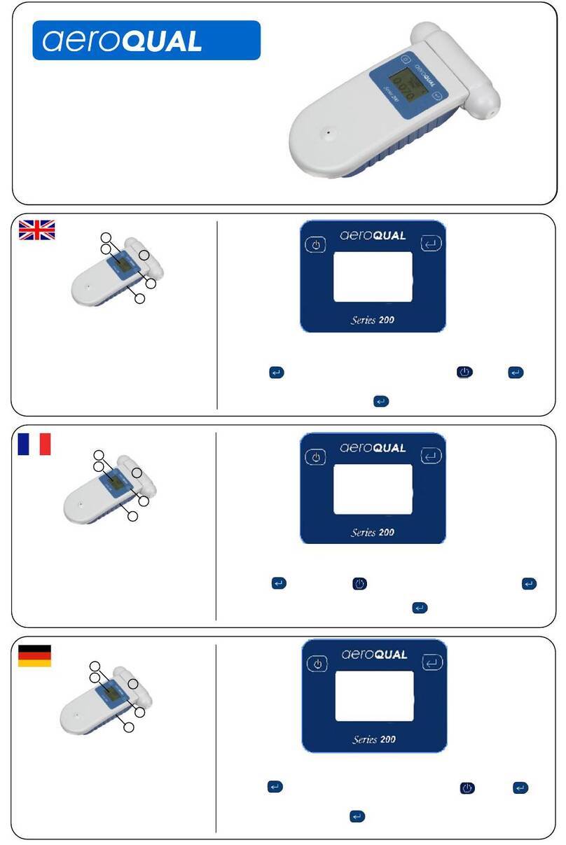
Aeroqual 200 series User manual

Aeroqual Limited
460 Rosebank Road, Avondale
Auckland, New Zealand
t +64 9 623 3013
f +64 9 623 3012
e technical@aeroqual.com
aeroqual.com

MRK-D-0022 V4 Aeroqual Series 200, 300 & 500 User Guide Page | 2
Table of Contents
1Monitor Components....................................................................................................................4
2Quick Start Guide..........................................................................................................................5
2.1 Connecting the Battery............................................................................................................5
2.2 Charging the Battery ...............................................................................................................6
2.3 Connecting the Sensor Head..................................................................................................6
3Sensor Heads ................................................................................................................................7
3.1 Sensor Head Technology........................................................................................................7
3.2Sensor Head Variants.............................................................................................................8
3.3 Sensor Head Warm-Up...........................................................................................................9
3.4 Sensor Head Failure Modes ...................................................................................................9
4Monitor Operation.......................................................................................................................10
4.1 Powering On/Off and Standby ..............................................................................................10
4.2 Menu Functions.....................................................................................................................11
5Aeroqual Monitor Software (Series 500)...................................................................................17
5.1 Computer Requirements.......................................................................................................17
5.2Connect to Monitor................................................................................................................17
5.3 Monitor Setup........................................................................................................................17
5.4 Data Logging.........................................................................................................................18
6External Control Wiring (Series 300 & 500)..............................................................................22
6.1 Wiring for Alarm.....................................................................................................................22
6.2 Wiring for Control ..................................................................................................................23
6.3 Wiring the 0-5 V Analogue Output ........................................................................................23
7Calibration....................................................................................................................................24
7.1 Calibration FAQ's ..................................................................................................................24
7.2 Calibration Certificate............................................................................................................26
7.3 Calibration Accessory ...........................................................................................................26
7.4 Bump Test.............................................................................................................................27
7.5 Zero Calibration.....................................................................................................................27
7.6 Span Calibration (Series 300 and 500).................................................................................28
7.7 Health and safety during calibration......................................................................................29
8Specifications..............................................................................................................................32
8.1 Dimensions............................................................................................................................33
9Optional Accessories: ................................................................................................................34
9.1 Temperature and Relative Humidity Sensor (HH TRH)........................................................34
9.2 Handheld Enclosure (HH ENC).............................................................................................34
9.3 Remote Sensor Head Adaptors (AS R10 / AS R13).............................................................36
10 Troubleshooting..........................................................................................................................37

MRK-D-0022 V4 Aeroqual Series 200, 300 & 500 User Guide Page | 3
10.1 Sensor Failure.......................................................................................................................39
11 Technical Support.......................................................................................................................39
12 Care and Maintenance................................................................................................................40
12.1 Disposal / Recycling..............................................................................................................40
13 Appendix......................................................................................................................................41
13.1 General Guidelines on the Measurement of Gases..............................................................41
13.2 Specific Guidelines on the Measurement of Ozone..............................................................42
13.3 Sensor Characteristics..........................................................................................................43
13.4 Gas Sensitive Electrochemical (GSE) Sensor - Ozone........................................................44
13.5 Gas Sensitive Electrochemical (GSE) Sensor - Other..........................................................45
13.6 Particulate Matter Sensor Head PM10 / PM2.5 sensor........................................................47
13.7 Volatile Organic Compound (VOC) sensors .........................................................................49
14 Copyright .....................................................................................................................................55
15 Software License.........................................................................................................................55
16 Terms and Conditions ................................................................................................................55
17 Statements of Compliance.........................................................................................................56

MRK-D-0022 V4 Aeroqual Series 200, 300 & 500 User Guide Page | 4
1 Monitor Components
The following components are supplied with each monitor:
Component
Series 200
Series 300
Series 500
Monitor base
Sensor head
(If ordered)
12 VDC AC/DC
Lithium Smart
Charger
Battery pack –
11.1V Lithium
Polymer
USB to monitor
cable
Two-way PS2
adapter cable
NOTE: Data logging software for the Series 500 can be found at:
https://www.aeroqual.com/support/product-software
Please check that all these components have been supplied, if any of the components are missing,
contact your distributor, or Aeroqual at: sales@aeroqual.com.
Replacement batteries, sensor heads and other accessories can be purchased separately.

MRK-D-0022 V4 Aeroqual Series 200, 300 & 500 User Guide Page | 5
2 Quick Start Guide
The following actions need to be completed before the monitor is ready for use:
1. Connect the battery.
2. Charge the battery.
3. Connect the sensor head.
2.1 Connecting the Battery
The battery is shipped installed in the monitor but disconnected. Follow the steps below to connect
the battery.
Push tabs on both
sides in.
Holding in both tabs
pull the blue battery
cover upwards. If it is
difficult to move then
you may be squeezing
too tight.
With the cover
removed the battery is
visible. Push the base
of the battery forward
to clear the clips at the
bottom.
The battery is shipped
unplugged.
Insert the connector
and firmly depress.
Gently tug on the
wires to ensure the
plug does not come
free.
Reinsert the battery by
locating the top right
hand corner under the
top right tab.
Push down the top left
side of the battery,
position the battery into
place under the clips at
the bottom.
Re-engage the top
hinge of the cover,
swing down and shut,
ensuring tabs lock cover
into place.

MRK-D-0022 V4 Aeroqual Series 200, 300 & 500 User Guide Page | 6
2.2 Charging the Battery
IMPORTANT
Switch off the monitor before removing the sensor head
Do not use the battery pack for any other purpose than operating the Aeroqual monitor
Do not disassemble or deface the batteries as this may cause burns
Do not incinerate or heat as this may cause burns, the batteries may burst or cause the release of
toxic materials
Do not short circuit as this may cause burns
Use only batteries approved by Aeroqual and recharge your battery only with the AC/DC adaptor
supplied with the instrument
Never use any charger or battery that is damaged or worn out
Batteries must be recycled or disposed of properly. They must not be disposed of in municipal
waste
Never charge the battery in a hermetically sealed container
Perform charging at temperatures between 0 °C to 45 °C
With the adaptor plugged in and monitor off allow 3 hours for the battery to fully charge.
A new battery's full performance is achieved only after a number of complete charge and discharge
cycles. A fully charged battery will run for approximately 8 hours depending on the sensor head
being used.
Smart Charger LED Status
Red LED = Battery is charging OR battery is fully charged and monitor is on.
Green LED = Battery is fully charged and monitor is off.
NOTE: The unit can be charged when switched on but it will charge more slowly. The battery
can be charged with the sensor head installed or removed from the base.
2.3 Connecting the Sensor Head
IMPORTANT
Do not insert/remove the sensor head while the monitor is switched on. This may damage the
unit. If the sensor head is removed under these conditions without AC/DC adapter connected,
the unit will automatically shut down.
Always place the sensor head perpendicular to the air flow to avoid damage to the sensor.
Sensors require a warm-up period before operation, refer to Section 3.3.
To avoid damage to the sensor, do not shake or invert the monitor when a sensor is attached.
Sensor heads have a keyed connector and are shaped to ensure correct insertion into the monitor
base. When the sensor is fully inserted you can turn on the monitor. Sensors require a warm-up
period before operation, refer to Section 3.3.

MRK-D-0022 V4 Aeroqual Series 200, 300 & 500 User Guide Page | 7
3 Sensor Heads
IMPORTANT
Do not insert/remove the sensor head while the monitor is switched on. This may damage the
unit. If the sensor head is removed under these conditions without AC/DC adapter connected,
the unit will automatically shut down.
Always place the sensor head perpendicular to the air flow to avoid damage to the sensor.
Sensors require a warm-up period before operation, refer to Section 3.3.
3.1 Sensor Head Technology
Aeroqual sensors are as unique as the monitors and accessories they are compatible with. Below are
the different sensor technologies and the designs you may encounter.
Type
Description
Design
GSS
Our gas sensitive semiconductor (GSS) sensor uses proprietary
sensing material, built in automatic baseline correction (ABC) and
interference rejection. This combination results in ppb resolution and a
highly linear response.
GSE
Our gas sensitive electrochemical (GSE) sensors generate nano-amp
currents proportional to the gas concentration. Aeroqual uses low noise
electronics to capture these signals resulting in low detection levels.
LPC
Our laser particle counter (LPC) for Particulate Matter (PM)
measurements uses optimized signal processing using low noise
electronics, we add algorithms to correct for interferences, e.g.
humidity.
NDIR
Our non-dispersive infrared (NDIR) sensor uses infra-red light, a
narrow band-pass filter and photodiode to measure the intensity of light
at the gas absorption band. The light intensity is proportional to the gas
concentration.
PID
Our photoionization detector (PID) sensor uses a krypton filled UV
lamp to ionize VOC gas molecules and generate a current that is
proportional to the VOC concentration. The PID sensor responds to a
wide range of VOCs and is industry recognized.
All sensors in the portable range benefit from active sampling and come factory calibrated.
NOTE: Sensor head colours vary by gas type, not all colours are shown in the table above.
Outlet
(On side)
Inlet
(Mesh screen)
Inlet
Outlet
(On end)

MRK-D-0022 V4 Aeroqual Series 200, 300 & 500 User Guide Page | 8
3.2 Sensor Head Variants
Sensor heads come in a variety of shapes and configurations to suit different gases and accessories.
Sensor Head Type 1
Compatible with: Series 200 / 300 / 500
Standard Remote Sensor Kit and Series 900
fixed monitors
Not compatible with: Industrial Enclosure,
and IP 41 Remote Senor Kit
Sensor Head Type 2
Required for: Industrial Enclosure, and IP41
Remote Sensor Kit and Series 930 fixed monitors
Sensor Head –Carbon Dioxide
Compatible with: Series 200 / 300 / 500
Standard Remote Sensor Kit
Not compatible with: Industrial Enclosure,
and IP 41 Remote Senor Kit
Sensor Head –Particulate Matter
Compatible with: Series 200 / 300 / 500
Standard Remote Sensor Kit
Not compatible with: Industrial Enclosure, and
IP 41 Remote Senor Kit
Sensor Head Type 4
Required for:Series 940 fixed monitors only

MRK-D-0022 V4 Aeroqual Series 200, 300 & 500 User Guide Page | 9
3.3 Sensor Head Warm-Up
When the monitor is switched on the sensor needs to warm up to burn off any contaminants, there are
two stages:
3 minutes; sensor WARMING UP, no measurement
7 minutes; sensor stabilising, measurement is flashing
When not being used, keeping the monitor in ‘standby’ mode will keep the sensor heated and prevent
a build-up of contaminants.
If the sensor is new (or unused for long periods) it can take up to 24 hours for the message
WARMING UP (or SENSOR FAILURE in older models) to disappear. Should the message remain
after this time, a genuine sensor failure may have occurred, see Section 10.
For an ozone sensor, 24 hours is a conservative time to burn off contaminants and achieve its stated
performance specification. In most instances this will be achieved well within 24 hours. The warm-up
period can be reduced by subjecting the sensor to elevated ozone levels for a short period. For
example, 0.1 ppm of ozone for 5 minutes typically reduces the warm-up time to < 30 minutes.
3.4 Sensor Head Failure Modes
There are two possible sensor failure modes that will be indicated on the display:
SENSOR FAILURE, REPLACE SENSOR
The sensor head should be replaced as there has been a component failure.
SENSOR AGING (Ozone Low/Ultra Low sensor heads only)
The sensor has reached the end of its usable life, the measurement readings can no longer
be relied upon to be within specification.
See also Trouble shooting in Section 10.

MRK-D-0022 V4 Aeroqual Series 200, 300 & 500 User Guide Page | 10
Alarm mute
Scroll down
Scroll up
4 Monitor Operation
The following instructions detail the operation and set up of the monitor:
Series 200
Series 300
Series 500
4.1 Powering On/Off and Standby
To turn the monitor on: Press and hold the power button until the screen activates. The monitor
will turn on and the display will appear as below:
After 5 seconds the display will change to indicate the type of sensor head and the monitor will enter
WARMING UP mode (see Section 3.3), after which the main display will appear as below:
or
Gas only Gas / Temp / RH
The battery indicator does not represent the remaining battery life.
Mand L(Monitor ID and Location ID) only show on the Series 300 and 500.
Only 3 parameters can be shown on the screen at one time. If a sensor captures more
than one parameter (e.g. PM2.5 /PM10 sensor head) they will scroll up the screen.
AEROQUAL
MONITOR
S500 V6.4
LITHIUM BATTERY
O3 ULOW
WARMING UP
3 MINUTES
SV 7.1
M 01
L 01
O3 ULOW
0. 080
ppm
M 02
L 03
O3 UL0.080
TEMP 21.6C
RH 35.1%
ppm
M 02
L 03
Enter
Power button
Series 300 / 500
Power / Scroll button
Series 200

MRK-D-0022 V4 Aeroqual Series 200, 300 & 500 User Guide Page | 11
To turn the monitor off: Press and hold the power button for 2 seconds until the monitor
beeps. The display will now be blank and operation of the monitor will cease.
To activate standby mode: With the monitor on, press the power button once. This will stop
operation of the monitor; however the sensor will be kept warm.
This mode is used to conserve power between operations but keep the sensor ready to measure the
gas concentration with only a short warm-up phase needed. In this mode the display will show the
sensor type and standby symbol .
To return the monitor to operational mode press the power button .
NOTE: When using a Carbon Dioxide sensor head in standby mode, the sensor runs at full power
and the fan remains on.
4.2 Menu Functions
Use the enter button to enter the SETUP menu.
Use the scroll up and scroll down buttons to navigate, select options, and change values.
Use the enter button to confirm the selections and changes.
Series 200 Series 300 Series 500
To exit a menu; complete the action for the menu you are in, or scroll to EXIT and press enter .
Each menu item is covered in the following sub-sections.
EXIT
MONITOR ID
UNITS
OUTPUT SENSOR
ALARM POINTS
CONTROL POINTS
MUTE KEY
CLOCK SETUP
EXIT
LOCATION ID
MAX MIN AV
CALIBRATE
MONITOR SET UP
EXIT
LOCATION ID
MAX MIN AV
CALIBRATE
MONITOR SETUP
LOGGING SETUP
EXIT
ZERO CAL
UNITS
MIN MAX AV
MUTE KEY
LOG FREQ
CLEAR LOG
LOGGING
Series 500 only

MRK-D-0022 V4 Aeroqual Series 200, 300 & 500 User Guide Page | 12
4.2.1 ZERO CAL
See section 7.4
4.2.2 UNITS
In the Series 300 and 500, UNITS is found under MONITOR SETUP. Use the scroll up and scroll
down buttons to select the required units, press enter to confirm the selection.
ppm or mg/m3for gases
mg/m3for particulate matter (PM) only
If a temperature and humidity sensor is attached, choose from:
°C or °F
4.2.3 MAX MIN AV
When activated, MIN MAX AV displays the minimum, maximum and average readings from the start
of the measurement cycle.
To activate:
Select MAX MIN AV
Select START to initiate the measurement cycle and return to the setup menu
Scroll to EXIT to return to the main display
The readings will scroll up the screen
NOTE: Only three parameters will be shown on the screen at one time.
In the Series 300 and 500, the MAX MIN AV cycle can also be initiated from the main display by
holding down the scroll down button for 2 seconds until the unit beeps. Hold down the scroll
down button again for 2 seconds to stop the measurement cycle.
When the MAX MIN AV cycle is initiated, the display should read as seen below:
or
NOTE: The RD value is the current reading. The speed of the display scrolling is dictated by the
slowest sensor. The display will scroll every time a new set of readings have been taken.
O3 UL
PPM
RD 0.010
MIN 0.005
MAX 0.024
AVE 0.015
O3 UL TEMP RH
PPM C %
RD 0.010 23 50
MIN 0.005 22 50
MAX 0.024 25 56
AVE 0.015 24 54

MRK-D-0022 V4 Aeroqual Series 200, 300 & 500 User Guide Page | 13
4.2.4 ZERO CAL / CALIBRATE
Select ZERO CAL on the Series 200, or CALIBRATE on the Series 300 and 500.Then to enter the
CALIBRATE menu, hold down the mute button and scroll down button for 2 seconds. ZERO
CAL or SPAN CAL can be selected.
For information on how to calibrate the sensor heads please refer to Section 7.
4.2.5 MUTE
Mute silences the audible feedback ‘beeps’that occur when you press a button.
Select MUTE KEY (Series 200) or under MONITOR SETUP (Series 300 and 500).
Press the enter to silence the audible feedback ‘beeps’, the word MUTED will appear
next to MUTE KEY.
NOTE: On the Series 200, if the device is turned off the mute settings will be returned to the default
state and mute will have to be reset when the monitor is restarted.
4.2.6 LOCATION ID (Series 300 & 500)
The location ID provides a means of identifying the location where a measurement was taken. This
can be used to quickly trace a measurement back to a location. Location ID is logged for each
measurement.
Select LOCATION ID under MONITOR SETUP.
Use the scroll up and scroll down buttons to select the required ID.
Press enter to confirm the ID and return to the setup menu.
4.2.7 MONITOR ID (Series 300 & 500)
Each monitor can be numbered to identify them quickly when more than one is in use. Data is tagged
with the monitor ID at the time it is downloaded to the PC, so you can use more than one monitor with
a single instance of PC software (S500 only). Each record in the database contains the following;
date, time, monitor id, location id, sensor type, sensor reading.
Select MONITOR ID under MONITOR SETUP
Use the scroll up and scroll down buttons to select the required ID
Press enter to confirm the ID and return to the setup menu
In the Series 500 data logging mode, only the Location ID will be logged. The monitor ID is loaded to
the database at the time of data upload (where it is logged).
NOTE: For compatibility purposes the database records for earlier versions of the S500 (v5.x) default
to monitor ID = 1 and location ID = 1. This cannot be changed.

MRK-D-0022 V4 Aeroqual Series 200, 300 & 500 User Guide Page | 14
4.2.8 OUTPUT SENSOR (Series 300 & 500)
The output sensor selection will determine which sensor parameter the alarm, control points and
buzzer refer to.
Select OUTPUT SENSOR under MONITOR SETU
Use the scroll up and scroll down buttons to select the required parameter
Press enter to confirm the selection and return to the setup menu
NOTE: The 0-5v analogue signal will also operate on the selected sensor and measurement range.
4.2.9 ALARM POINTS (Series 300 & 500)
Select ALARM POINTS under MONITOR SETUP, ALARM HI will display
Use the scroll up and scroll down buttons to select the required high concentration
Press enter to confirm the change, ALARM LO will display
Use the scroll up and scroll down buttons to select the required low concentration
Press enter to confirm the change, BUZZER display will display
Use the scroll up and scroll down buttons to enable or disable the alarm
Press enter to confirm the selection and return to the setup menu
If the alarm is disabled a P will show on the right hand side of the alarm mute symbol on the main
display, highlighting that the alarm has been permanently muted.
Alarms indication:
ALARM HI = accompanied by a fast beeping sound
ALARM LO = accompanied by a slow beeping sound
The alarm can be muted by pressing the mute button on the display screen. However, this is only
a temporary mute and will only mute the alarm during that specific alarm condition. Once the
concentration has moved back into the alarm limits the settings will reset. To turn off the mute
permanently follow instructions to disable the alarm in Section 4.2.5.
4.2.10 CONTROL POINTS (Series 300 & 500)
Select CONTROL POINTS under MONITOR SETUP, CONTROL HI will display
Use the scroll up and scroll down buttons to select the required high concentration
Press enter to confirm the change, CONTROL LO will display
Use the scroll up and scroll down buttons to select the required low concentration
Press enter to confirm the selection and return to the setup menu

MRK-D-0022 V4 Aeroqual Series 200, 300 & 500 User Guide Page | 15
4.2.11 CLOCK SETUP (Series 500)
Select CLOCK SETUP under MONITOR SETUP, HOUR will display,
Use the scroll up and scroll down buttons until the correct hour is displayed
Press enter to confirm the change, MINUTES will display
Repeat steps for seconds, month, day and year
NOTE: The clock is a 24 hour clock (e.g. 14:30 = 2:30 pm)
4.2.12 LOGGING SETUP (Series 500)
The Series 500 monitor can log up to 8188 data points divided by the number of parameters being
logged. Parameters include; gas sensors, temperature and optional relative humidity sensor and for
the PM sensor PM2.5 and PM10 are treated as separate parameters.
Select LOGGING SETUP under MONITOR SETUP, LOG FREQ 1
MIN will appear on the display.
Use the scroll up and scroll down buttons to select the
required frequency in 1 minute intervals
Press enter to confirm the selection, CLEAR LOG will display
Use the scroll up and scroll down buttons to select YES
or NO
Press enter to confirm the selection, LOGGING will display
Use the scroll up and scroll down buttons to select ON or
OFF
Press enter to confirm the selection and return to the setup menu
Logging short cuts
The data log can also be cleared directly from the main display screen by holding down the
mute button for 2 seconds until the monitor beeps (if the monitor keys are not muted).
Data logging can also be both started and stopped directly from the main display screen by
pressing the scroll up button for two seconds until the monitor beeps (if the monitor keys
are not muted).
Month: Day: Year
Hours: Minutes: Seconds
14:30:12
Oct 07 12
CLEAR LOG
YES NO
LOGGING
ON OFF
LOG FREQ.
1 MIN

MRK-D-0022 V4 Aeroqual Series 200, 300 & 500 User Guide Page | 16
Logging indicator
When data logging is initiated a triangle will appear on the main display screen. The triangle is an
indication that data logging is active, and is also used as an indication of the presence of data, as
below:
An empty triangle indicates that no data is stored
A filling triangle indicates that some data is stored in the memory. The triangle will fill up in
10% increments.
A full triangle indicates that the memory is full and needs downloading to the PC.
For direct logging to a PC using Aeroqual Monitor Software refer to Section 5.4.

MRK-D-0022 V4 Aeroqual Series 200, 300 & 500 User Guide Page | 17
5 Aeroqual Monitor Software (Series 500)
Aeroqual Monitor Software for the Series 500 is available for free download from the Aeroqual
website: https://www.aeroqual.com/support/product-software
5.1 Computer Requirements
USB to monitor cable (supplied with the Series 500)
Window OS version 2000 or later required –iOS platforms are not supported
512 Mb RAM or more recommended
1 GHz processor speed or faster recommended
NOTE: S500 V6.5 software will support Series 500 monitors with firmware S500 V5.x, earlier
versions are incompatible.
5.2 Connect to Monitor
Connect the Series 500 monitor to a computer using the cable supplied and turn on
Launch the Aeroqual Monitor PC software and click on the toolbar to search for the
monitor. The unit will be detected automatically and connect
Test the connection by clicking on the tool bar. This will display the Monitor Name,
Version and ID Number
5.3 Monitor Setup
The Software can be used to setup the following on the Series 500 monitor:
Monitor ID
Location ID
Units
Logging Frequency
Output Sensor
Alarm Settings
Control Settings
Clock
To setup:
Monitor Setup (or Ctrl P), the Monitor Setup dialog box will
appear
Type in, or scroll up or down to set the desired values
Click the ‘Save’button to synchronise the monitor values with
those on the PC
In order to log data it is essential that the clock on the monitor is
set to the real time. Click ‘Update Clock’. This can also be done
on the monitor (Section 4.2.11)
NOTE: If the temperature and humidity sensor is connected, an option to select Temperature unit will
appear.

MRK-D-0022 V4 Aeroqual Series 200, 300 & 500 User Guide Page | 18
5.4 Data Logging
The Aeroqual Monitor Software can be used to log data directly from a Series 500 monitor to a PC.
For instructions on how to log data on the monitor itself, refer to Section 4.2.12.
5.4.1 PC Data Logging
Ensure that the USB cable is connected to the monitor and to the PC. Click File Start PC Data
Logging, or click on the toolbar. The data will be logged directly to the database on the PC. No
data will be stored on the monitor memory in this mode of operation. However, if PC data logging is
stopped by clicking on the toolbar, the data will start to be stored in the Series 500 monitor
memory.
5.4.2 Downloading Logged Data from Series 500
Logged data from the monitor memory can be downloaded by clicking File Download Logged
Data or by clicking on the toolbar.A data download progress bar will appear while the data is
downloading.
If for any reason, the data download does not complete, is terminated or stops:
Turn off the monitor to prevent any data loss.
Delete the data that has been downloaded to the PC
Close the PC software program and repeat the downloading process with the monitor on,
connected and with the PC software running.
NOTE: Downloaded data will not be removed from the monitor memory. To delete the logged data
from the monitor refer to Section 4.2.12.
5.4.3 Graphs
While logging directly to a PC, the Real Time View Graph or the Logged Data Graph can be
accessed via ‘Data’ on the menu bar. Logged data graph can be viewed be clicking Data
GraphLogged Data. Each parameter is shown in individual tabs.
To Configure graphs:
Graph Default Style or by right clicking
on the graph and selecting ‘Graph Style’
To zoom in:
Click on the graph and drag to create a yellow
rectangle. The yellow rectangle shows the
selected area the graph will zoom into.
To save graphs:
Right click on the graphs to save or print.
Graphs will be saved as a JPG file
To reset the graph to the default:
Right click and select ‘Reset to Default’

MRK-D-0022 V4 Aeroqual Series 200, 300 & 500 User Guide Page | 19
In the Logged Data Graph the date, time and sensor type to be viewed can be selected. The Monitor
and Location ID can also be selected.
NOTE: The Monitor ID is not logged on each record in the monitor but will be stored in the database
against each measurement when the data is downloaded. The data will be tagged with
whatever the monitor ID is at the time of download. Conversely, the location ID is logged on
each record in the monitor.
5.4.4 Tables
While logging directly to a PC, the Real Time Table View or Logged Data Table View can be
accessed via the Data menu on the menu bar.
In the logged data table view the date, time and sensor type can be selected to view the relevant data.
The Monitor and Location ID can also be selected. Once these parameters have been selected click
‘Apply’ to filter the data and display the selected parameters.
The logged data table will display up to 7 days of data on each page. Click the arrows at the
bottom of the table to view the previous or next 7 days of data within the filtered data set.
NOTE: Only one monitor ID can be viewed at a time in the logged data table view.

MRK-D-0022 V4 Aeroqual Series 200, 300 & 500 User Guide Page | 20
5.4.5 Daily View
This is a summary for each day, from midnight to
midnight, of the Minimum, Maximum and Average
readings over the 24 hour period. To launch the Daily
View window:
Data Daily Analysis
Select the date range, monitor and location ID
and click ‘Apply’ or click ‘View All’
Click ‘Export’ to export summary data files to
programs such as MS Excel.
NOTE: Only one monitor ID can be viewed at a time in
the daily view table.
5.4.6 Exporting Data
To export the database:
File Export Logged Data
Select the range of data to be exported using
the date, time, monitor ID, location ID and
sensor type parameters
Click ‘Export’, select a directory, choose a file
format (either plain text or MS Excel file)
Click ‘Save’ to export the data to the chosen
location
NOTE: Only one monitor ID can be exported at a time. Up to 50,000 lines of file can be exported at
once. If more than 50,000 lines need to be exported it will need to be carried out in two
exports.
Other manuals for 200 series
2
This manual suits for next models
2
Table of contents
Other Aeroqual Measuring Instrument manuals
