Aeroqual AQM 65 User manual
MRK-D-0034 V2.0 Aeroqual AQM 65 User Guide Page | 1

MRK-D-0034 V2.0 Aeroqual AQM 65 User Guide Page | 1
Table of Contents
1Description of AQM 65................................................................................................................6
1.1 Gas Modules......................................................................................................................7
1.1.1 Gas Module design.........................................................................................................7
1.1.2 Gas flow through modules............................................................................................ 10
1.2 Particulate matter (TSP, PM10, PM2.5, PM1.0) modules..................................................12
1.2.1 Particle Monitor modules..............................................................................................12
1.2.2 Particle Profiler modules...............................................................................................14
1.2.3 Comparison between the Particle Monitor and the Particle Profiler................................ 14
1.3 Optional external sensors and auxiliary modules ..............................................................15
1.3.1 Temperature and Humidity Sensor ...............................................................................16
1.4 Thermal management system and system manager module.............................................16
1.5 Interfacing with the AQM 65 using Connect and Cloud .....................................................18
1.5.1 Aeroqual Connect......................................................................................................... 18
1.5.2 Aeroqual Cloud ............................................................................................................19
1.6 Quick start guide ..............................................................................................................21
2Set-up ......................................................................................................................................22
2.1 Unpacking........................................................................................................................ 23
2.2 Initial assembly and powering the AQM 65 for the first time .............................................. 23
2.2.1 Wire AC mains power and initial start-up.......................................................................24
2.2.2 Attach PM inlet.............................................................................................................25
2.2.3 Attach gas inlet............................................................................................................. 28
2.2.4 Wire external third party sensors ..................................................................................30
2.3 Set up MOXA G3111 HSPA modem for remote communication........................................ 31
2.4 Re-packing and transport ................................................................................................. 32
3Connect Software.....................................................................................................................33
3.1 Connecting to the AQM 65 for the first time ...................................................................... 34
3.2 Options for connecting to the AQM 65..............................................................................35
3.2.1 Direct WIFI................................................................................................................... 36
3.2.2 Direct connection using Ethernet cable......................................................................... 36
3.2.3 Connecting over a local area connection (LAN) ............................................................ 36
3.2.4 Connecting using a cellular modem .............................................................................. 37
3.3 Resetting the communication settings back to factory settings..........................................39
3.4 Apps for instrument control and calibration .......................................................................40
3.4.1 Manage Data app.........................................................................................................40
3.4.1.1 Charts................................................................................................................... 41
3.4.1.2 Table....................................................................................................................41
3.4.1.3 Download data...................................................................................................... 42
3.4.1.4 Manual sync .........................................................................................................43
3.4.2 Service and Calibration app..........................................................................................44
3.4.3 Diagnostics and Advanced ...........................................................................................45
3.4.4 Journal.........................................................................................................................46
3.5 User permission types: Administrator, Engineer, User and Instrument licences.................47

MRK-D-0034 V2.0 Aeroqual AQM 65 User Guide Page | 2
3.5.1 Instrument licences.......................................................................................................47
4Maintenance and service..........................................................................................................48
4.1 Safety requirements.........................................................................................................48
4.2 Gas flow meters and flow measurement...........................................................................49
4.3 AQM 65 Service mode and using the Journal to document service...................................50
4.3.1 Manual service mode ...................................................................................................50
4.3.2 Journal.........................................................................................................................50
4.4 List of maintenance procedures........................................................................................ 51
4.4.1 Tools required for regular service and maintenance...................................................... 51
4.4.2 Replace gas sample inlet filter...................................................................................... 52
4.4.3 Measure and adjust AQM 65 inlet flowrate and module flow rates.................................53
4.4.3.1 Measure main gas inlet flow rate...........................................................................53
4.4.3.2 Measure the flow rate of the individual modules ....................................................54
4.4.3.3 Adjust the AQM 65 inlet flow rate and replacement of the gas sample pump. ........55
4.4.4 Replace filter on Particle Monitor or Particle Profiler......................................................56
4.4.5 Flow check and flow adjustment of the Particle Monitor and Particle Profiler .................57
4.4.5.1 Using the buffer chamber when checking the flow of the Particle Profiler...............58
4.4.5.2 Flow adjustment of Particle Monitor.......................................................................59
4.4.5.3 Flow adjustment of Particle Profiler....................................................................... 60
4.4.6 Leak check Particle Monitor and Particle Profiler...........................................................61
4.4.6.1 Leak check a Particle Monitor...............................................................................61
4.4.6.2 Leak check a Particle Profiler................................................................................ 62
4.4.7 Zero calibration check and flow check of Particle Module..............................................63
4.4.7.1 Check zero baseline of Particle Monitor ................................................................63
4.4.7.2 Check the auto zero calibration flow rate of the Particle Monitor............................64
4.4.7.3 Check the zero baseline of the Particle Profiler .....................................................65
4.4.8 Clean the Particle Monitor TSP inlet, particle trap and cyclone......................................65
4.4.9 Replace pumps in pump module...................................................................................66
4.4.10 Leak check gas module............................................................................................67
4.4.11 Add, remove or replace a gas module.......................................................................68
4.4.11.1 Removing a module without replacing it ............................................................69
4.4.11.2 Replacing a module with another of the same type............................................69
4.4.11.3 Adding a new module........................................................................................ 70
4.4.12 Thermal management system, maintenance and troubleshooting .............................71
4.4.12.1 Changing the internal set point temperature ......................................................71
4.4.12.2 Loss of thermal control......................................................................................72
4.4.12.3 Clean TMS cassette and condenser fins ...........................................................73
4.4.12.4 Check TMS compressor gas pressure and re-fill ...............................................75
4.5 Factory calibration of Particle Monitor and Particle Profiler................................................81
4.6 Service frequency guidelines............................................................................................81
4.7 Aeroqual Advanced Engineer Certification........................................................................83
5Gas module calibration.............................................................................................................85
5.1 Calibration frequency .......................................................................................................86
5.2 Guidelines for purchasing calibration gas cylinders and gas regulators .............................87
5.2.1 Purchasing calibration gas: recommended cylinder concentrations and sizes................87

MRK-D-0034 V2.0 Aeroqual AQM 65 User Guide Page | 3
5.2.2 Cylinder of certified zero air and certified CO2 for CO2 calibration ................................88
5.2.3 Considerations for gas cylinder size..............................................................................88
5.3 Calibration safety .............................................................................................................90
5.4 Aeroqual portable calibration systems: AirCal 1000, and AQM O3CAL. ............................90
5.5 Aeroqual integrated calibration system AirCal 8000..........................................................92
5.6 Calibration accessories: tubing, fittings, gas regulator.......................................................93
5.6.1 Inert fluoropolymer tubing for module calibration...........................................................93
5.7 Calibration procedure.......................................................................................................95
5.7.1 Site inspection and instruments pre-checks ..................................................................95
5.7.2 Using the AQM 65 Journal to log calibration details ......................................................95
5.7.3 Overall calibration workflow: .........................................................................................96
5.7.4 Instrument checks before starting calibration ................................................................97
5.7.5 Setting up calibration equipment...................................................................................98
5.7.5.1 Zero calibration using the AirCal 1000...................................................................98
5.7.5.2 Span calibration using the AirCal 1000..................................................................99
5.7.5.3 Span calibration using the AQM O3CAL ozone calibrator.................................... 100
5.7.5.4 Zero and span calibration using the AirCal 8000 ................................................. 101
5.7.6 Perform the zero calibration........................................................................................ 102
5.7.6.1 Wait for the module response to stabilise towards zero air .................................. 102
5.7.6.2 Decide if a zero offset adjustment is required...................................................... 103
5.7.6.3 Upload the new offset and check the offset has been applied correctly................ 103
5.7.7 Perform the span calibration....................................................................................... 104
5.7.7.1 Choose your span gas concentration .................................................................. 104
5.7.7.2 Wait for the module response to stabilise towards the span gas.......................... 105
5.7.7.3 Decide if a gain adjustment is required................................................................ 106
5.7.7.4 Calculate a new gain, and decide if the gain should be applied ........................... 106
5.7.8 Record your results in the Journal............................................................................... 107
5.7.9 Pack up and final instrument checks, schedule the next calibration............................. 107
6Particle Monitor calibration...................................................................................................... 108
6.1 Factory Servicing ........................................................................................................... 108
6.2 Field Calibration............................................................................................................. 108
6.3 Steps to perform a K factor correction............................................................................. 109
7Appendices ............................................................................................................................ 111
Appendix 1 Troubleshooting....................................................................................................... 111
Appendix 2 AQM 65 dimensions and weight............................................................................... 114
Appendix 3 DC Power consumption of the AQM 65.................................................................... 115
Appendix 4 CO2 module calibration ........................................................................................... 117
Appendix 5 AQM 65 site installation and commissioning with mounting examples ...................... 119
Appendix 6 Gas calibration systems from other suppliers ........................................................... 124
8Copyright................................................................................................................................ 126
9Compliance ............................................................................................................................ 126
10 Warranty............................................................................................................................. 126


MRK-D-0034 V2.0 Aeroqual AQM 65 User Guide Page | 5
Alternative sources of information and help
In addition to this User Guide, Aeroqual offers other sources of information which can assist in the
operation of the AQM 65. The Aeroqual website contains many brochures and technical notes and
user guides for all products: www.aeroqual.com.
The training website contains a comprehensive document library of technical notes and service and
calibration templates to download and print. The training website has detailed descriptions of service
activities and calibration and installation examples and is updated regularly. Video tutorials are
featured heavily. Go to training.aeroqual.com. Contact technical@aeroqual.com to receive access.
The online training website has sections on all the key topics
Where possible, references to online material will provided throughout this user guide
Online
reference
training.aeroqual.com
Online video
https://vimeo.com
Contact your distributor in your local country for initial technical support. If local technical support is
MRK-D-0034 V2.0 Aeroqual AQM 65 User Guide Page | 6
1 Description of AQM 65
The Aeroqual AQM 65 is a compact air quality station designed for precise measurement of ambient
pollution and environmental conditions.
The AQM 65 platform is modular, each measurement parameter is selected by the user and added to
the platform as an individual measurement module. An AQM 65 can be configured with 1- 6 gas
modules as well as particulate and weather sensors.
A typical customised configuration might include ozone (O3), nitrogen dioxide (NO2), carbon monoxide
(CO), sulfur dioxide (SO2) PM10, and PM2.5,temperature, humidity, wind speed and direction.
Measurement modules can easily be added, removed or replaced after the AQM 65 has been
installed in the field.
The AQM 65 is fully weather proof (IP 65) and houses a power module, thermal management system,
embedded PC running Aeroqual Connect software and the user selected analyser modules.
Users can make use of Aeroqual’s web-based Cloud software services for data storage and
management of networks of AQM 65s.
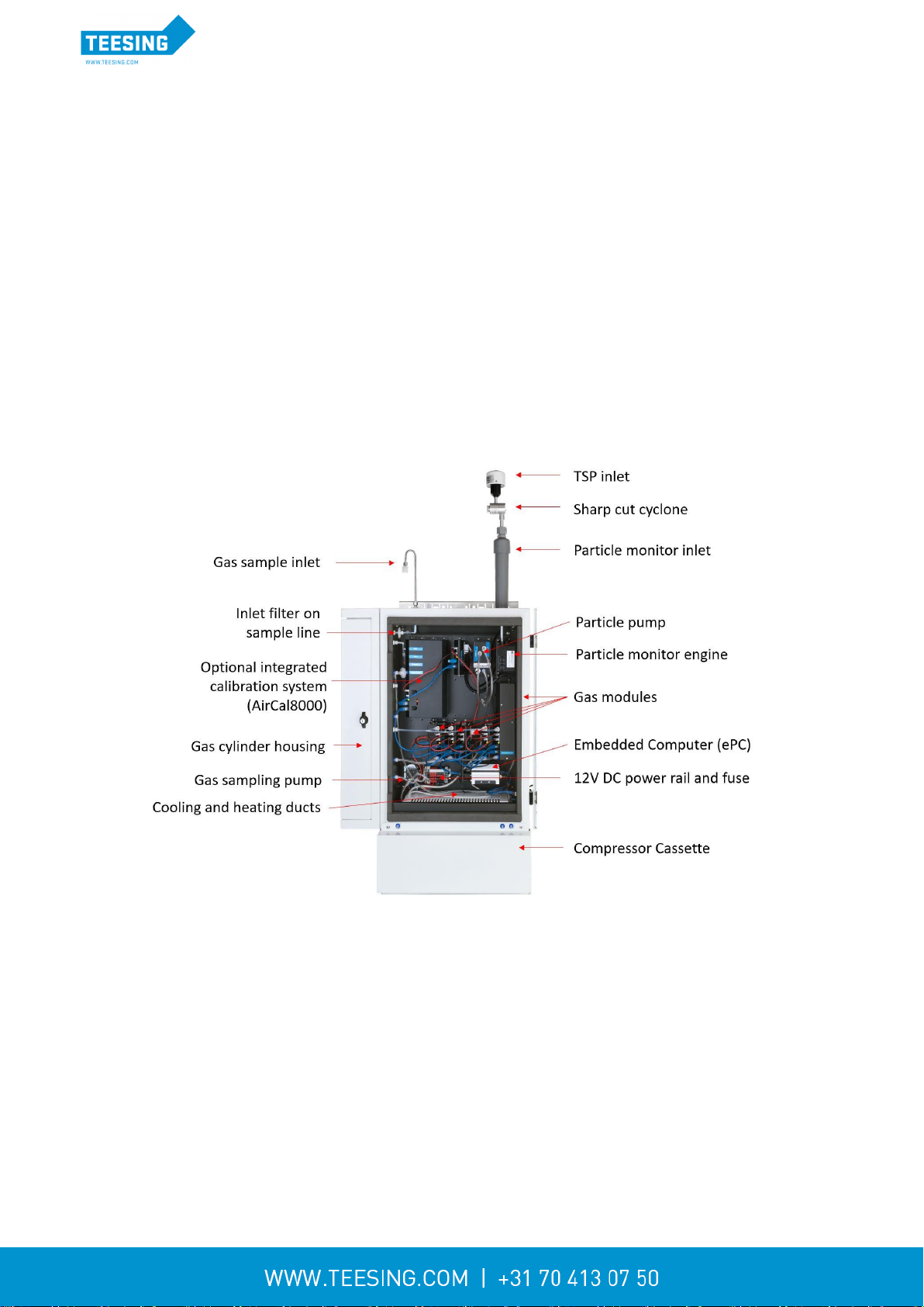
The AQM 65 can be fitted with an optional internal calibration system called the AirCal8000 shown in
Figure 1-1
Figure 1-1 AQM 65 with key parts labelled

MRK-D-0034 V2.0 Aeroqual AQM 65 User Guide Page | 7
1.1 Gas Modules
Several gas modules are available for integration in to the AQM 65. A full list of the gas modules
which can be included is given in Table 1.1.
The following section provides an overview of AQM 65 module design. A full specification of module
performance is given in Table 1-1
1.1.1 Gas Module design
The AQM 65 can be configured with a range of gas modules. Two gas module designs are used in
the AQM 65. These two designs are shown schematically in Figure 1-2 A list of which gas modules
use which design is given in Table 1-1.
Direct design: The gas is passed directly to the sensor continuously
Zero switching design: The module uses a solenoid to switch between a zero path which
removes the target gas and creates a “zero” or baseline measurement, and a measurement
path which measures the ambient air. The final measurement in ppm is an arithmetic
combination of the zero and sample measurement.
Figure 1-2 Gas sensor modules are based on two different designs
Each gas module uses a sensor technology that is most suited to its target gas. For example the
Ozone module uses gas sensitive semiconductor (GSS) sensor and the VOC module uses a photo
ionisation detector (PID). A list of which sensor technology is used in each gas module is given in
Table 1-1
The gas flow rate is controlled using a critical orifice, shown in red in Figure 1-2. The flow rate is
different for each module. A list of flow rates for each module is given in Table 1-1. The gas modules
come in different sizes, the size of the gas modules varies depending upon the size and number of
components used inside the module such as the zero scrubbers for example. The size of each gas
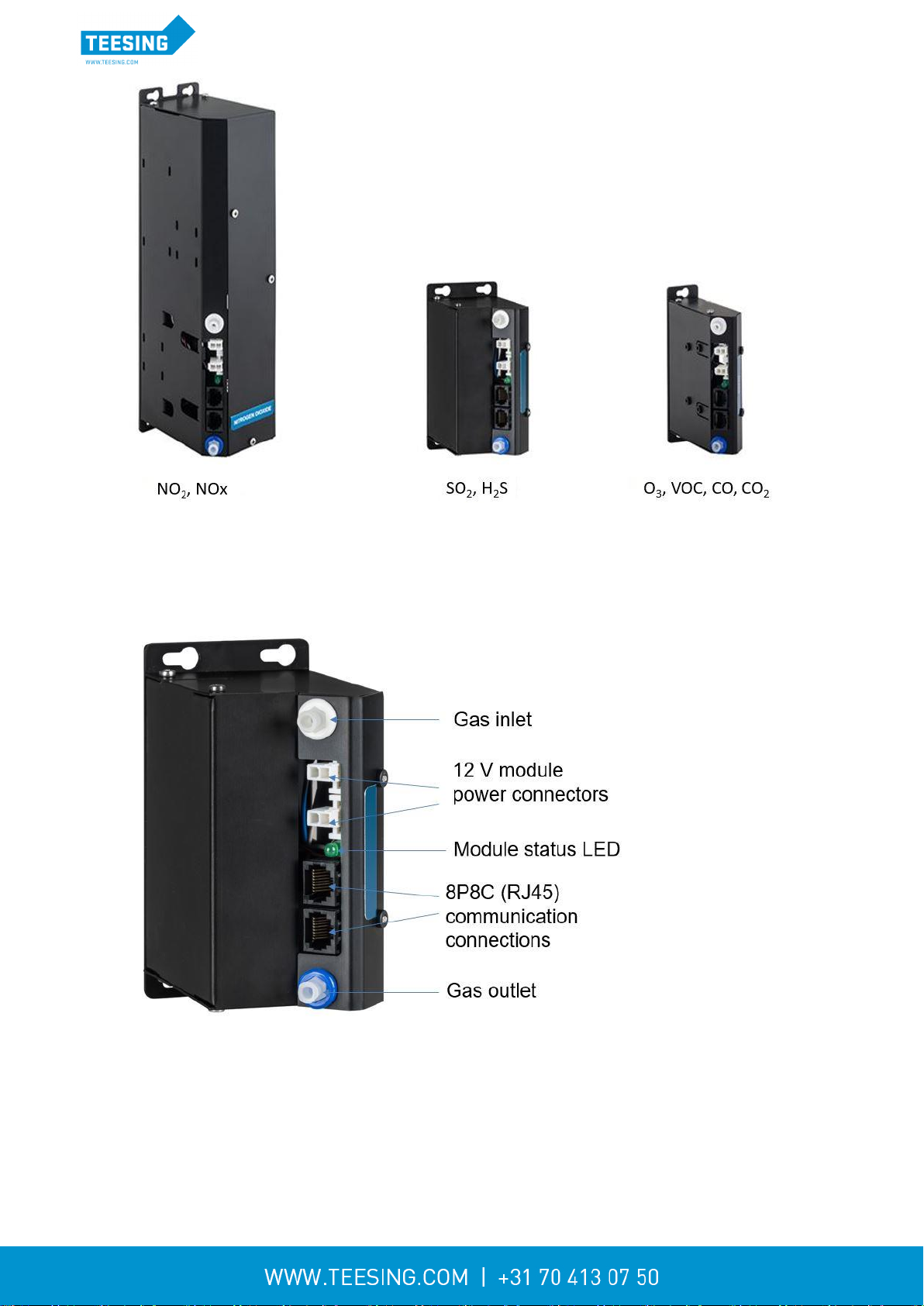
module is shown in Figure 1-3.
MRK-D-0034 V2.0 Aeroqual AQM 65 User Guide Page | 8
Figure 1-3 Gas sensor modules come in three different sizes
Each gas module contains a gas inlet port (white ring) and a gas exhaust port (blue ring). Each
module contains two 12 V power connectors to allow the module to be connected to a 12 V power
bus. Each module contain two RJ-45 connections to allow the module to be connected to the RS-485
communications bus and each module contains a status LED.
Figure 1-4 Gas sensor module with key components labelled

MRK-D-0034 V2.0 Aeroqual AQM 65 User Guide Page | 9
Module
Range
(ppm)
Resolution
Sensor
Technology
Module
Size
Measurement
method
Serviceable
parts
Module
flow rate
ml min-1
Lower
detectable
limit
(ppm)
Precision
Drift 24
hour
Expected
module
lifetime
Zero
(ppm)
Span %
of F.S
O3
0 –0.5
0.001
GSS
Small
Zero Switching
none
110 - 130
0.001
< 2% of
reading
0.001
2 –3 years
or 0.002 ppm
0.2 %
NO2
0 –0.2
0.001
GSS
Large
Zero Switching
none
55 - 65
0.001
< 3% of
reading
0.001
2 –3 years
or 0.003 ppm
0.5 %
NOx
0 –0.5
0.001
GSS
Large
Zero Switching
none
55 - 65
0.001
< 3% of
reading
0.001
2 –3 years
or 0.003 ppm
0.2 %
SO2
0 –10.0
0.001
GSE
Medium
Zero Switching
none
55 - 65
0.009
< 3% of
reading
0.001
1 –2 years
or 0.003 ppm
0.2 %
CO
0 –25.0
0.001
GSE
Small
Direct
none
55 - 65
0.040
< 3% of
reading
0.02
1 –2 years
or 0.050 ppm
0.2 %
H2S
0 - 10
0.001
GSE
Medium
Zero Switching
none
55 - 65
0.012
< 3% of
reading
0.001
1 –2 years
or 0.012 ppm
0.6 %
VOC
0 - 20
0.001
PID
Small
Direct
Lamp
(6 months)
140 - 160
0.010
< 2% of
reading
0.005
1 –2 years
or 0.010 ppm
0.2 %
CO2
0 - 2000
1
NDIR
Small
Direct
none
140 - 160
10
< 2% of
reading
1
1 –2 years
or 10 ppm
0.6 %
Table 1-1 Module specification table
NOTE: Performance criteria are provided for factory test conditions and may change without notice
MRK-D-0034 V2.0 Aeroqual AQM 65 User Guide Page | 10
1.1.2 Gas flow through modules
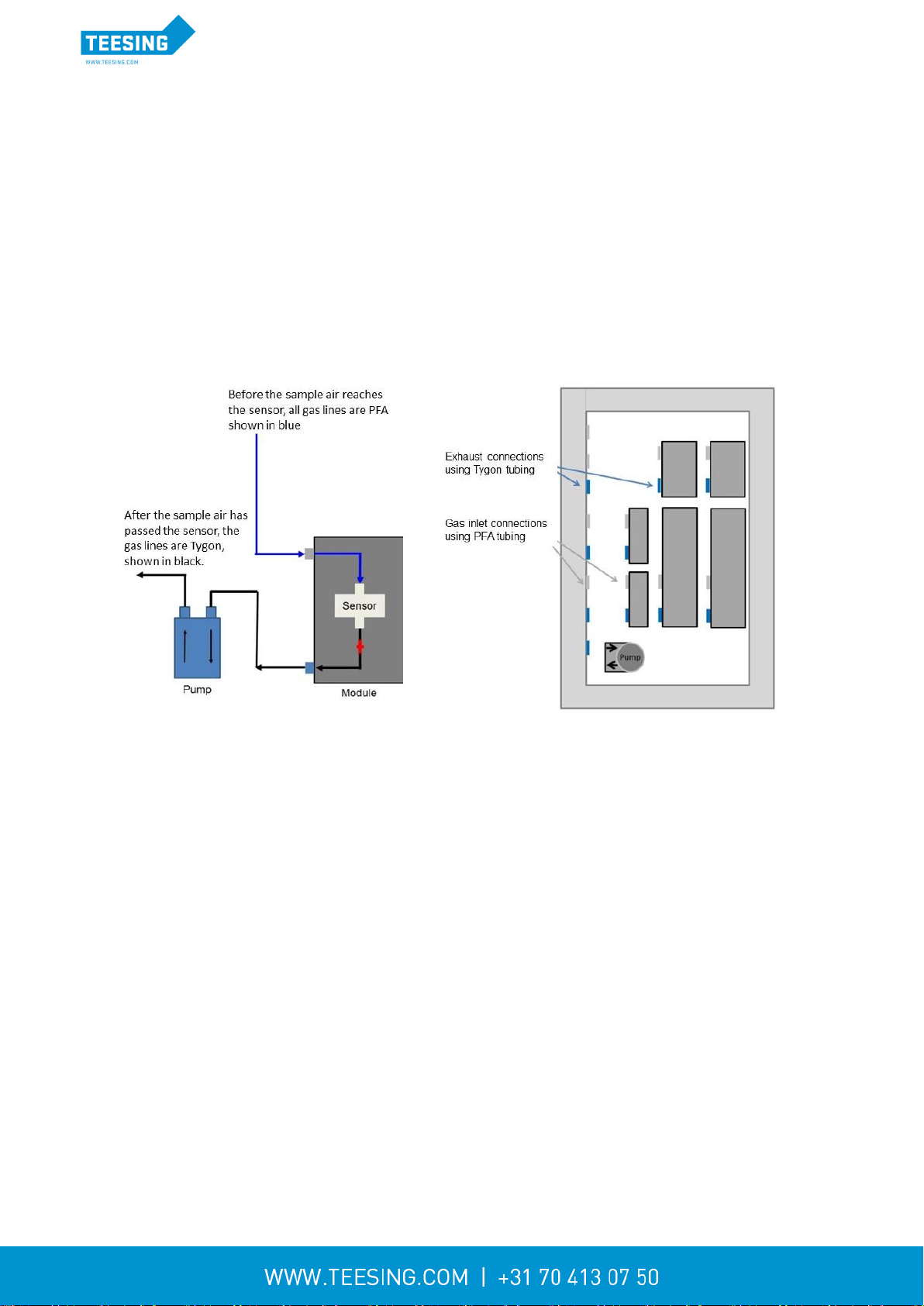
The gas flow through all of the gas modules is powered by a single diaphragm pump at the bottom left
of the enclosure. The vacuum side of the pump is connected to the gas outlet (exhaust) of each
module. This is illustrated for a single gas module in Figure 1-5.
The pump pulls sample air through the module and then pushes air out through the exhaust so that
the sample air passes through the pump only after it has been measured in the module.
There are two different types of tubing material used to handle the gas flow.
Before the gas reaches the sensor, all of the tubing material is rigid non-reactive PFA.
After the sample has passed the sensor all of the tubing is flexible R3603 Tygon
Figure 1-5 A single pump is used for all gas modules. The vacuum port of the pump is connected to the
outlet of each gas module
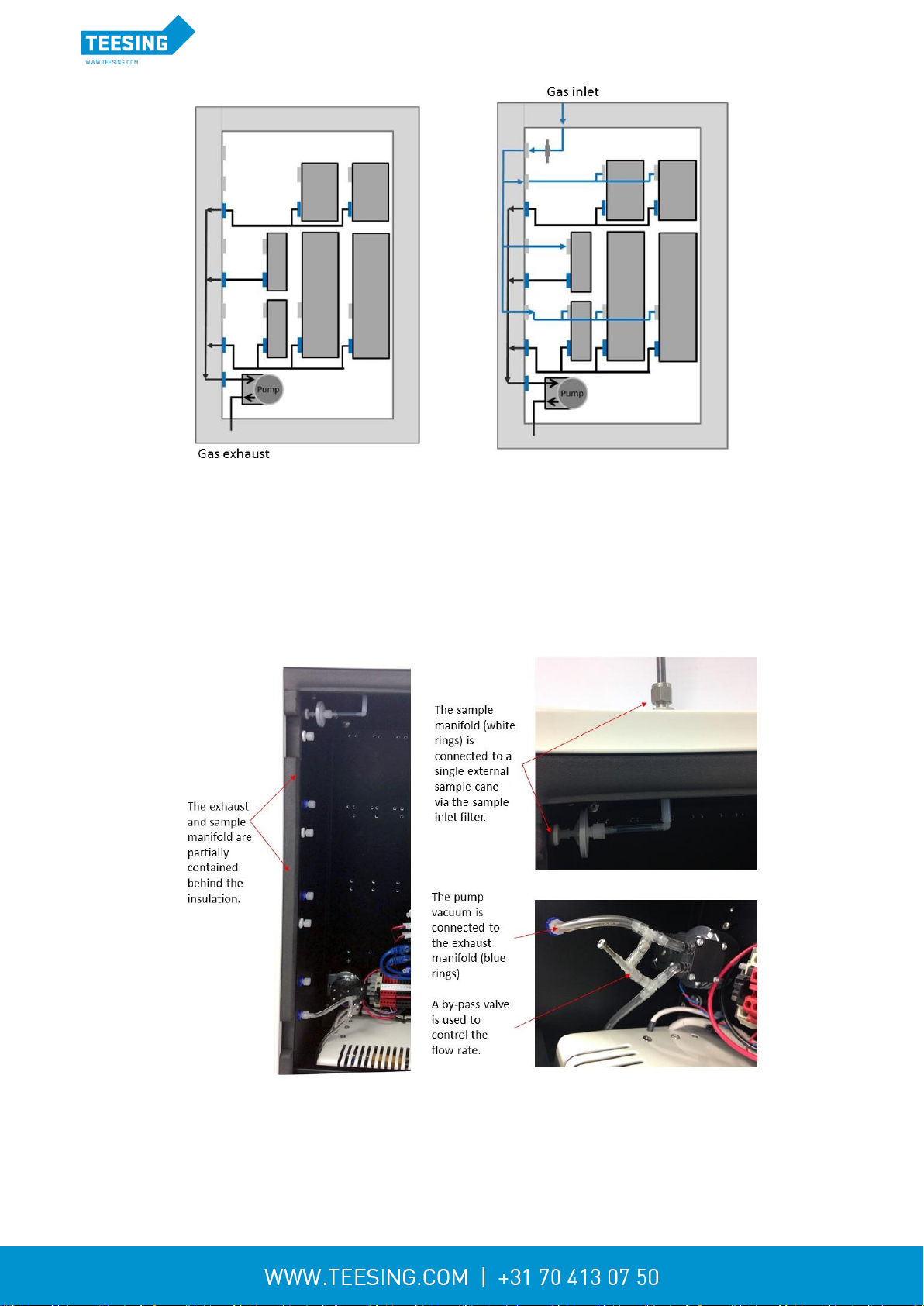
The gas modules are connected in two rows inside the AQM 65 enclosure. There is one main gas
inlet for sampling ambient air and one gas exhaust port both shown in Figure 1-6. Each gas module is
connected to the pump via the Tygon exhaust manifold. The modules are connected in parallel as
shown in Figure 1-6 on the left side. Each gas module is connected to the inlet via the PFA sample
manifold, also in parallel as shown in Figure 1-6 on the right.
MRK-D-0034 V2.0 Aeroqual AQM 65 User Guide Page | 11
Figure 1-6 Each module is connected to the exhaust and inlet manifolds in parallel.
Part of the manifold is protected on the inside left wall of the enclosure, behind the insulation so it
cannot be seen. The pump uses a flow bypass valve to regulate the pressure on the vacuum side of
the pump, this by-pass valve is used to regulate the overall flow through all of the module
simultaneously. This is discussed in more detail in Section 4.4.3.3.
Figure 1-7 The vacuum side of the pump is connected to the exhaust manifold (blue rings). The AQM 65
inlet is connected to the inlet manifold (white rings). The pump has a by-pass valve to control flow rate.
MRK-D-0034 V2.0 Aeroqual AQM 65 User Guide Page | 12
1.2 Particulate matter (TSP, PM10, PM2.5, PM1.0) modules
The AQM 65 can measure particulate matter such as PM10 and PM2.5. There are three separate
modules:
1. for measuring the particulate (optical engine), there are two types of optical engine:
the Particle Monitor uses a nephelometer (See Figure 1-8)
the Particle Profiler use an optical particle counter (OPC) (See Figure 1-11)
2. for handling the data transfer (I/O module)
3. for controlling the flow rate (pump module)
The Particle Monitor measures a single size fraction such as TSP or PM10 or PM2.5or PM1.0. A
Particle Profiler measures four size fractions simultaneously, TSP and PM10.0 and PM2.5 and
PM1.0.
The Particle Monitor has an international performance certification (MCERTS), and is more accurate
than the Particle Profiler.
The sample flow for the Particle Monitor and Particle Profiler is separate from the gas sample flow.
There is a separate pump, a separate inlet and a separate exhaust.
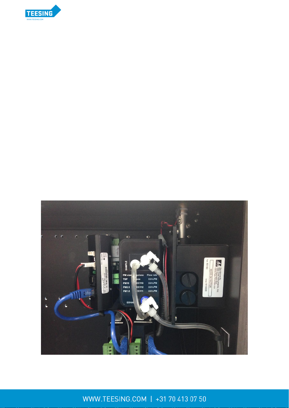
1.2.1 Particle Monitor modules
The Particle Monitor uses a custom Met One near forward scattering nephelometer to measure
particle concentration and a sharp cut inlet cyclone to select the particle size. This module is shown
on the far right in Figure 1-8.
An AQM 65 can be configured with one Particle Monitor to measure a single particle size or an AQM
65 can be configured with two separate Particle Monitor systems so that two size fractions can be
measured at the same time.
All of the modules used in the Particle Monitor system are held in the top row of the AQM 65. Figure
1-8 shows an AQM 65 with one Particle Monitor installed (three modules total) and Figure 1-9 shows
an AQM 65 with two Particle Monitors installed (six modules total).
Figure 1-8 The Particle Monitor uses three module: a) the optical engine on the far right, b) the pump
module in the middle, c) the I/O module on the left

MRK-D-0034 V2.0 Aeroqual AQM 65 User Guide Page | 13
In the single Particle Monitor configuration, the three modules are held in the top right corner. If the
AQM 65 contains two Particle Monitor then all six modules will be in the top row.
The standard configuration is to have the PM10 on the right and the PM2.5 on the left.
Figure 1-9 Two Particle Monitors can be installed in an AQM 65, each Particle Monitor will have three
modules each
The size selection is determined by the sharp cut cyclone on the Particle Monitor inlet on the outside
of the AQM 65 shown in Figure 1-10.
An AQM 65 that has a single Particle Monitor can be configured to measure either of these four size
fractions simply by changing the inlet cyclone and making a small change in the software. This is
described in Section 4.5 of the online training website.
Online
reference
training.aeroqual.com AQM 65 technical training Section 4.5
Figure 1-10 Size selection in the Particle Monitor is determined by the sharp cut cyclone on the inlet

MRK-D-0034 V2.0 Aeroqual AQM 65 User Guide Page | 14
1.2.2 Particle Profiler modules
The AQM 65 uses a Met One optical particle counter to measure four particle size fractions
simultaneously. There is no sharp cut cyclone used in the Particle Profiler; both the concentration and
size are measured inside the optical particle counter.
The three modules for the Particle Profiler are installed in the top right side of the AQM 65 enclosure.
An AQM 65 will only ever have one Particle Profiler installed.
The Particle Profiler has the sample and purge filters mounted on the outside of the optical module,
(in the Particle Monitor they are held inside).
Figure 1-11 The Particle Profiler uses three modules: a) the optical module on the far right, b) the pump
module in the middle, c) the electronics module on the left
1.2.3 Comparison between the Particle Monitor and the Particle Profiler
The Particle Profiler measures particulate concentrations using particle counting, it measures
multiple size fractions at the same time.
The Particle Profiler can measure TSP and PM10 and PM2.5 and PM1.0 without requiring a
sharp cut cyclone.
The Particle Monitor measures particulate concentrations by nephelometry, it measures TSP
or PM10 or PM2.5 or PM1.0 using a sharp cut cyclone.
There is a difference in the accuracy of the measurement for the Particle Profiler compared to
the Particle Monitor.
The Particle Profiler is not certified under the MCerts framework

MRK-D-0034 V2.0 Aeroqual AQM 65 User Guide Page | 15
Particle Monitor
Particle Profiler
Mass measurement
TSP or PM10 or PM2.5or PM1.0
Can be configured with two Particle
Monitors
TSP and PM10 and PM2.5 and
PM1.0
Accuracy
<±(2 μg/m3+ 5% of reading)
<±(5 μg/m3+ 15% of reading)
International certification
Yes, MCERTS for PM10
No certification
Factory calibration period
Every two years (24 months)
Every year (12 months)
Inlet flow rate
2.0 LPM
1.0 LPM
Table 1-2 Summary of the difference between the Particle Monitor and the Particle Profiler.
1.3 Optional external sensors and auxiliary modules
The AQM 65 can integrate a number of external sensors such as weather sensors, solar radiation and
noise sensors. These sensors are mounted outside the AQM 65 enclosure. An auxiliary module
(AUX) module is used to provide power to the external sensor and to process data from the sensor.
Some examples of external sensors are shown in Figure 1-12. The AUX module is shown in Figure
1-13. The external sensors which Aeroqual supports include (shown left to right in Figure 1-12.
MSO weather station from Met One
MK427 noise meter from Cirrus
WXT536 weather station from Vaisala
Windsonic from Gill Instruments
LI-200 Pyranometer from Li-Cor
MetOne MSO
weather station
Cirrus MK427
noise meter
Vaisala WXT536
weather station
Gill Instruments
Windsonic
Li-Cor LI-200
Pyranometer
Figure 1-12 The AQM 65 can integrate several external sensors
The AUX module uses a 12 way green connector plug to connect to the external sensor. The cable
from the external sensor is threaded through a water proof gland on the right outside wall of the AQM
65 and then connected to the green plug on the front of the AUX module.
Details on how to mount each external sensor and how each sensor is wired to the AUX module are
given in the online training:
Online
reference
training.aeroqual.com AQM 65 technical training Section 2.5
Online video
https://vimeo.com/130818560

MRK-D-0034 V2.0 Aeroqual AQM 65 User Guide Page | 16
Figure 1-13 The external sensors are connected to the green plug on the Aux module. The cable passes
through water proof glands on the right wall of the AQM 65
1.3.1 Temperature and Humidity Sensor
Every AQM 65 comes preconfigured with a temperature and humidity sensor located underneath the
AQM 65 enclosure. The temperature sensor is cable of measuring down to -40 oC and above 50 oC
with an accuracy of ±0.3 oC and humidity range is 0 to 100 %.with an accuracy of ± 2 %
1.4 Thermal management system and system manager module
The AQM 65 has a thermal management system (TMS) to maintain a stable internal temperature
irrespective of ambient temperature changes.
The internal set-point temperature is typically 30.0 ± 0.5 oC, but this can be changed to better suit the
external temperature conditions. Section 4.4.12 discusses this in detail.
The internal temperature is maintained using a fridge compressor for cooling and resistive heaters for
warming. The AQM 65 has thick insulation foam to minimise heat transfers through the wall and the
outer shell has a high performance reflective coating to minimise solar incidence.
The compressor is located on the bottom of the AQM 65 behind a protective shield and can be
removed if required. Temperature controlled air is passed into the compressor heat exchanger
through vents in the bottom of the enclosure. Air is then passed behind the back plate and then out a
vent at the top of the inside of the enclosure, Figure 1-14.

MRK-D-0034 V2.0 Aeroqual AQM 65 User Guide Page | 17
Figure 1-14 Air conditioned air is constantly circulated in the AQM 65 enclosure. Air comes in to the
enclosure at the top and exits through vents at the bottom
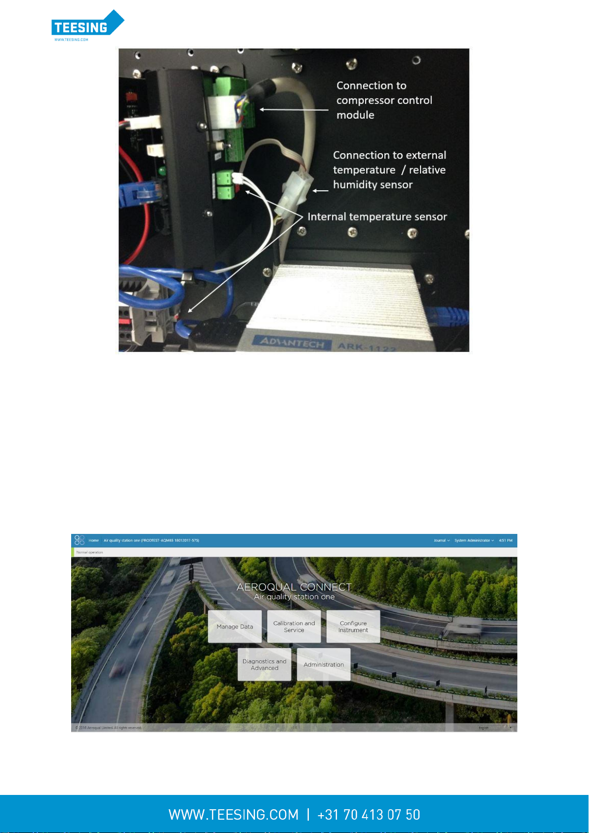
The system manager module shown in Figure 1-15 is used to measure the internal temperature and
control the compressor and heaters to maintain a constant internal temperature. The system manager
module also connects to the external temperature/RH sensor. The system manager module is placed
above and to the left of the embedded PC.
NOTE: The switch on the side of the system manager module has no function, it is deactivated.
MRK-D-0034 V2.0 Aeroqual AQM 65 User Guide Page | 18
Figure 1-15 The system manager module controls the internal temperature and also measures the
external temperature and relative humidity
1.5 Interfacing with the AQM 65 using Connect and Cloud
There is no software to download or install. Engineers who need to perform service or data users who
need to view or download data can do so using a browser on their PC, tablet or smart phone.
1.5.1 Aeroqual Connect
Aeroqual connect is the instrument’s operating system. The AQM 65 is controlled with an embedded
PC, (ePC) which is running a webserver. The user connects to the AQM 65 using a web browser such
as Firefox, Chrome or Safari. The connection can be over WIFI, Ethernet cable or cellular modem.
Aeroqual connect contains all of the tools necessary to view and download the data and maintain and
calibrate the AQM 65.
Figure 1-16 Aeroqual Connect is the operating system for the AQM 65. Aeroqual Connect is accessed
using a web browser.
MRK-D-0034 V2.0 Aeroqual AQM 65 User Guide Page | 19
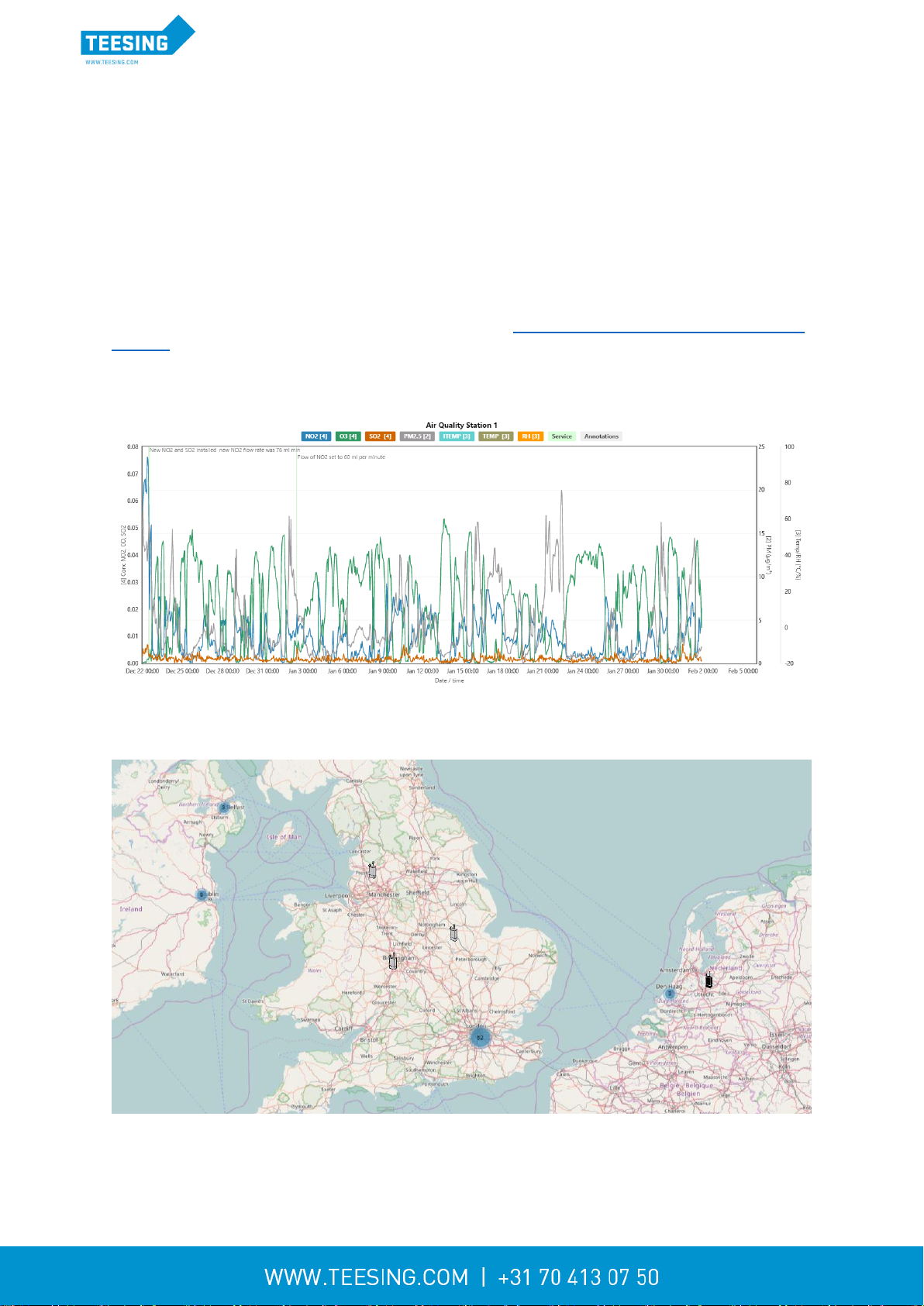
1.5.2 Aeroqual Cloud
Aeroqual Cloud gives you and other trusted users access to all of your instruments via secure third
party servers. Use Cloud to:
Communicate with your instrument from anywhere in the world at any time
Use advanced charting features such as wind roses and pollution roses
Receive fast and comprehensive technical support from your distributor or Aeroqual technical
support team.
Automatically export data to multiple users via email or to an FTP server.
Securely back up data in case of local data access issues.
Maintain service records in the Cloud Journal for auditing and engineer certification.
There are three versions of Aeroqual Cloud available: see www.aeroqual.com/product/air-monitoring-
software for details on what is included. Aeroqual Cloud Support is a free Cloud version and is used
to make technical support fast and efficient for the end user. Aeroqual Cloud basic and Cloud Plus
offer extra features and are paid for on a yearly basis.
Figure 1-17 Aeroqual Cloud has many useful features such as plotting multiple channels on a single
graph
Figure 1-18 Select multiple instruments by region, and plot data from multiple different instruments on
the same graph.
Other manuals for AQM 65
1
Table of contents
Other Aeroqual Measuring Instrument manuals


Popular Measuring Instrument manuals by other brands

Dynamica
Dynamica HALO XB-10/BIOmaster/VIS-20/ENVmaster instruction manual

Triacta
Triacta PowerHawk 6212 installation guide

Endress+Hauser
Endress+Hauser Prosonic T FMU30 Brief operating instructions

Rion
Rion VM-55 instruction manual
geo-FENNEL
geo-FENNEL FL 275HV-TRACKING user manual

MULTI MEASURING INSTRUMENTS
MULTI MEASURING INSTRUMENTS MET-1 instruction manual


