Aeroqual AQM 65 User manual

Aeroqual AQM60 User Guide
WWW.TEESING.COM | +31 70 413 07 50

Page | 2
Contents
User Guide Revision History ...................................................................................................................5
1. Description.......................................................................................................................................6
1.1. External Connections................................................................................................................. 7
1.2. Gas Modules.............................................................................................................................. 7
1.2.1. Gas Sensor Specifications.................................................................................................. 8
1.3. Thermal Management System .................................................................................................. 8
1.4. Sensirion SHT75 Temperature and Humidity Sensor ............................................................... 9
1.5. Auxiliary Module (Optional) ....................................................................................................... 9
1.6. Particle Monitor........................................................................................................................ 11
1.6.1. Nephelometer.................................................................................................................... 11
1.6.2. Inlet heater ........................................................................................................................ 11
1.6.3. Inbuilt filters....................................................................................................................... 11
1.7. Profiler ..................................................................................................................................... 12
1.7.1. Optical Particle Counter .................................................................................................... 12
1.7.2. Connections ...................................................................................................................... 12
1.7.3. Data Outputs..................................................................................................................... 12
1.8. Particle Mass Pump Modules.................................................................................................. 13
1.8.1. Profiler Pump Module........................................................................................................ 13
1.8.2. Nephelometer Pump Module ............................................................................................ 13
1.9. Electrical Connections............................................................................................................. 14
1.10. Pneumatic Connections........................................................................................................... 15
2. Set Up.............................................................................................................................................16
2.1. Unpacking................................................................................................................................ 16
2.2. Assembly................................................................................................................................. 16
2.2.1. Connect Mains Power....................................................................................................... 16
2.2.2. Connect Inlet System........................................................................................................ 18
2.2.3. Assembly of heated inlet for PM/Profiler (Optional).......................................................... 18
2.2.4. Connect third party sensors (Optional) ............................................................................. 19
2.3. Connect to the AQM 65........................................................................................................... 19
2.3.1. Initial Connection via Access Point Mode......................................................................... 20
2.4. Initial Commissioning............................................................................................................... 21
2.4.1. System Checks ................................................................................................................. 21
2.4.2. System Values .................................................................................................................. 22
2.4.3. Zero and Span Checks for Gas Modules.......................................................................... 22
3. Connecting to Aeroqual Connect and Cloud .............................................................................22
3.1. Connection Options................................................................................................................. 22
3.1.1. Client Mode....................................................................................................................... 22
3.1.2. Cellular Network Connection............................................................................................. 23
3.2. Aeroqual Cloud........................................................................................................................ 25
3.2.1. Manual Sync ..................................................................................................................... 26
3.3. Connection Scenarios.............................................................................................................. 26
4. Using Aeroqual Connect and Cloud ...........................................................................................27
4.1. Journal..................................................................................................................................... 27
4.2. Manage Data........................................................................................................................... 28
4.2.1. Charts................................................................................................................................ 28
4.2.2. Table ................................................................................................................................. 29
4.2.3. Download Data.................................................................................................................. 29
4.2.4. Auto Export (Only Available in Aeroqual Cloud)............................................................... 29
4.3. Calibration and Service ........................................................................................................... 30
4.3.1. Gain and Offset................................................................................................................. 30
4.3.2. AirCal 8000........................................................................................................................... 30
4.4. Diagnostics and Advanced...................................................................................................... 31
4.4.1. Diagnostics........................................................................................................................ 32
4.4.2. Module Settings ................................................................................................................ 32
4.5. Configure Instrument............................................................................................................... 32
WWW.TEESING.COM | +31 70 413 07 50

Page | 3
4.5.1. Settings ............................................................................................................................. 32
4.5.2. Configuring the System..................................................................................................... 33
4.5.3. Configuring the Sensors.................................................................................................... 33
4.5.4. Alerts (Only Available in Aeroqual Cloud)......................................................................... 34
4.5.5. Sensor List ........................................................................................................................ 34
4.5.6. Data filters......................................................................................................................... 34
5. Gas Module Calibration................................................................................................................35
5.1. Introduction.............................................................................................................................. 35
5.2. Calibration Gas Humidity......................................................................................................... 35
6. Calibration setup...........................................................................................................................36
6.1. Zero Calibration Procedure ..................................................................................................... 37
6.2. Span Calibration Procedure .................................................................................................... 38
6.2.1. Recommended Span Points and Acceptance limits......................................................... 39
6.2.2. Gas Phase Titrations......................................................................................................... 39
6.3. AirCal 8000 (Optional)............................................................................................................. 39
6.3.1. Overview ........................................................................................................................... 39
6.3.1. Gas Cylinder Housing ....................................................................................................... 41
6.3.2. Configuring the AirCal 8000 Scheduler............................................................................. 41
6.4. Calibration Standards and Equipment..................................................................................... 42
6.4.1. Calibration Gas ................................................................................................................. 42
6.4.2. Recommended Span Points and Cylinder Concentrations............................................... 42
6.4.3. Gas cylinders .................................................................................................................... 42
6.4.4. Gas regulators................................................................................................................... 43
6.4.5. Recommended fittings and Tubing for Aircal 1000........................................................... 44
6.5. Calibration Frequency.............................................................................................................. 45
7. Third Party Sensors......................................................................................................................46
7.1. Met One MSO.......................................................................................................................... 46
7.2. Vaisala Weather Transmitter WXT520.................................................................................... 46
7.3. Gill WindSonic ......................................................................................................................... 47
7.4. Cirrus MK427 Noise Sensor.................................................................................................... 47
7.5. Novalynx 240-200SZ Silicon Pyranometer.............................................................................. 48
8. Field Installation............................................................................................................................48
8.1. Site Selection........................................................................................................................... 48
8.2. Dimensions.............................................................................................................................. 49
8.3. Mounting.................................................................................................................................. 50
9. Maintenance...................................................................................................................................50
9.1. Safety Requirements............................................................................................................... 50
9.2. Maintenance Schedule............................................................................................................ 50
9.2.1. Standard AQM .................................................................................................................. 50
9.2.2. Particle Monitor ................................................................................................................. 51
9.2.3. Profiler............................................................................................................................... 51
9.3. AQM Maintenance Procedures ............................................................................................... 51
9.3.1. Replacing the Inlet Filter ................................................................................................... 51
9.3.2. Measuring Sample Inlet Flow Rate................................................................................... 52
9.3.3. Gas Sensor Module Flow Rate......................................................................................... 52
9.3.4. Leak Check Gas Sensor Plumbing................................................................................... 53
9.3.5. Removing and Replacing AQM Modules.......................................................................... 54
9.4. Particle Monitor........................................................................................................................ 54
9.4.1. Sample Flow Check .......................................................................................................... 54
9.4.2. Purge Flow Check............................................................................................................. 55
9.4.3. Sheath Flow Check........................................................................................................... 56
9.4.4. Leak Check ....................................................................................................................... 56
9.4.5. Manual Zero Air Check ..................................................................................................... 57
9.4.6. Fibre Span Check ............................................................................................................. 57
9.4.7. Laser Current Check......................................................................................................... 57
WWW.TEESING.COM | +31 70 413 07 50

Page | 4
9.4.8. Filter Changes................................................................................................................... 57
9.4.9. Cyclone and Inlet Cleaning............................................................................................... 58
9.4.10. Changing the Size Fraction Measured.............................................................................. 59
9.5. Profiler ..................................................................................................................................... 59
9.5.1. Sample Flow Check and Adjustment ................................................................................... 59
9.5.2. Sheath Flow Check........................................................................................................... 60
9.5.3. Leak Check ....................................................................................................................... 60
9.5.4. Filter Changes................................................................................................................... 61
9.5.5. Inlet Cleaning .................................................................................................................... 62
10. Troubleshooting............................................................................................................................62
10.1. AQM 65 Basics........................................................................................................................ 62
10.2. Particle Monitor/Profiler ........................................................................................................... 63
10.3. Diagnostics .............................................................................................................................. 64
11. Appendix........................................................................................................................................65
11.1. Guidelines................................................................................................................................ 65
11.2. Technical support .................................................................................................................... 65
11.3. Copyright ................................................................................................................................. 65
11.4. Compliance.............................................................................................................................. 66
WWW.TEESING.COM | +31 70 413 07 50

Page | 5
User Guide Revision History
Current version: 1.0
Description: User guide for AQM 65
This user guide is a newly created document for the use of the AQM 65.
Date
Revision number
Description of change
Affected
Sections
March 2015
1.0
New User Guide
All
WWW.TEESING.COM | +31 70 413 07 50

Page | 6
1. Description
The Aeroqual AQM 65 is a compact air quality station designed for precise measurement of ambient
pollution and environmental conditions. Its platform is configurable to measure a wide range of air
pollutants such as ozone (O3), nitrogen dioxide (NO2), carbon monoxide (CO), sulphur dioxide (SO2)
PM10, and PM2.5 as well as meteorological parameters such as temperature, humidity, wind speed and
direction.
The AQM 65 is complete air quality station consisting of a custom made IP65 rated aluminium
enclosure which houses a power module, thermal management system, embedded PC running
Aeroqual Connect software and user configured analyser modules.
Note 1: The placement of individual modules will vary depending on the user configuration
12 and 0 VDC
Terminals
Fuse Holder
Cooling ducts
Compressor
Cassette
Thermal
Management
System Module
Sample Pump
Embedded PC
PM Pump module
Gas Cylinder
Enclosure for
AirCal 8000
AirCal 8000
module
Inlet filter on
sample line
Gas Modules
(User Configurable)
PM Engine
Sharp Cut
Cyclone
TSP Inlet
PM Inlet
Sample Inlet
WWW.TEESING.COM | +31 70 413 07 50

Page | 7
1.1. External Connections
There are 4 external water tight glands located on the right hand side of the AQM 65 enclosure. The
black gland is an Ethernet output for use when a wired connection to the instrument is required (See
Section 3.1.1. for more information). The 3 other glands are designed to allow third party sensors to be
wired into the instrument.
1.2. Gas Modules
The AQM 65 can be configured with a range of gas modules. All modules are mounted onto the base
plate using 4 or 2 screws depending on the module size. Inlet and outlet tubes are connected to the gas
distribution manifold and exhaust respectively. The inlet tubing used is PFA 3.2ID x 0.75WT and the
exhaust tubing used is Tygon R3603.2ID x 1.6WT.
Sample Exhaust
RJ45 Connectors for RS485 bus
12VDC Power
Connectors
Sample inlet
Status LED
WWW.TEESING.COM | +31 70 413 07 50
Page | 8
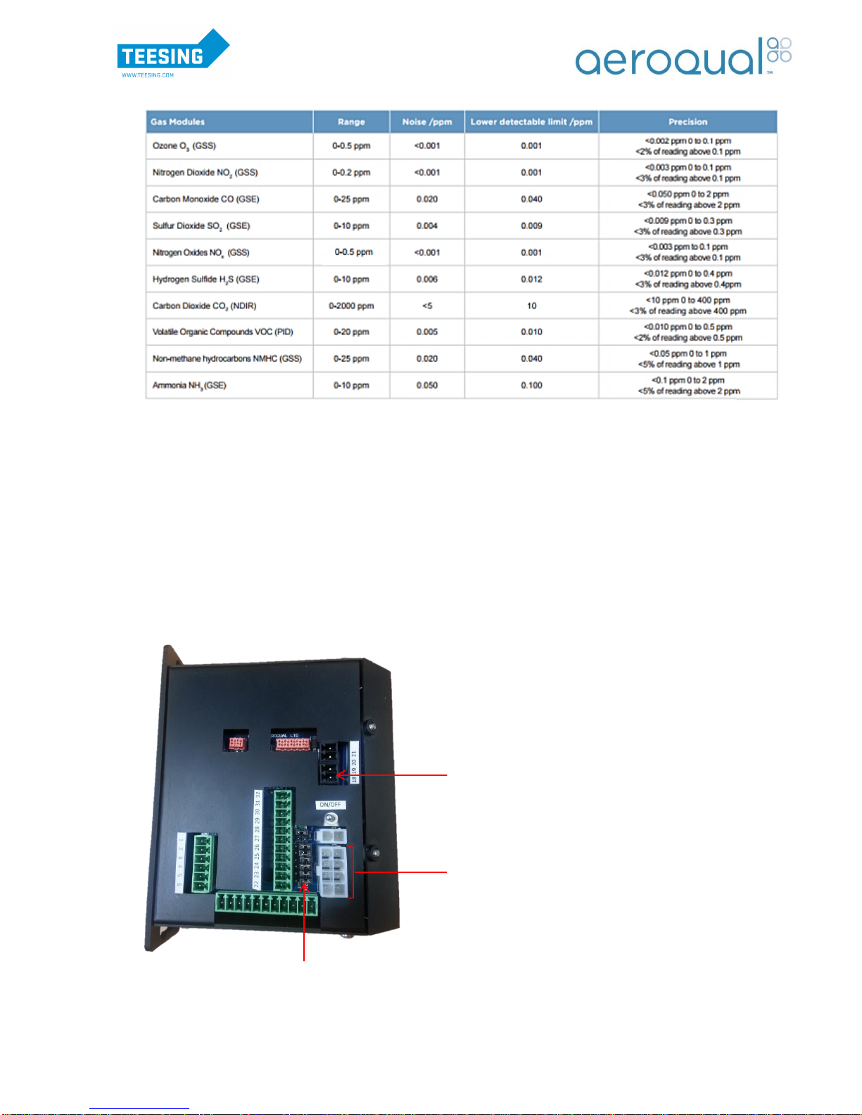
1.2.1. Gas Sensor Specifications
Note: The sensor specifications are subject to change; please contact Aeroqual for latest performance data
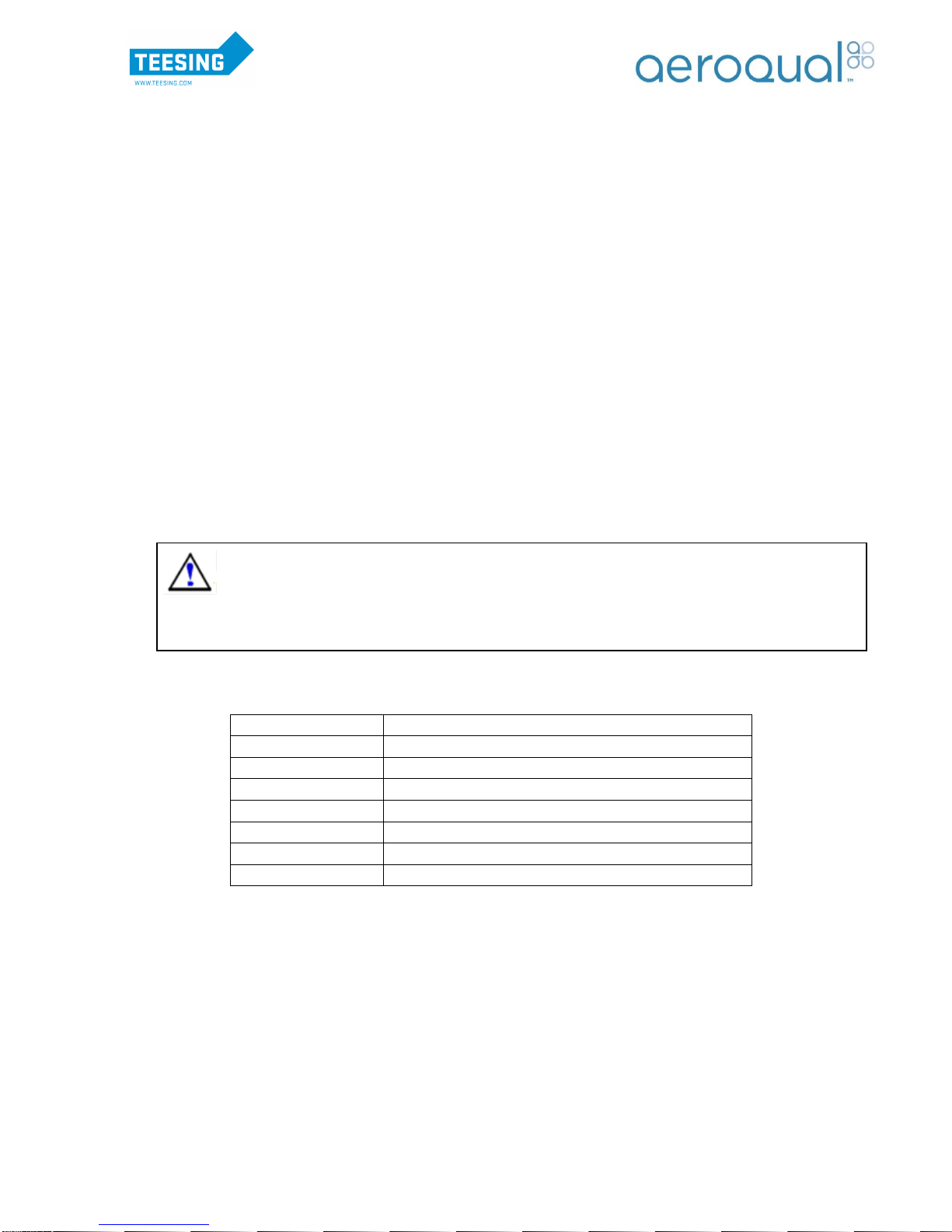
1.3. Thermal Management System
The AQM 65 has a thermal management control system to maintain a stable internal temperature
irrespective of ambient temperature changes. The TMS cassette is located at the base of the instrument
and comprises of a Danfoss compressor, IP55 cooling fan and ducting. The TMS cassette is separate
from the main enclosure and can be removed if required.
The control software is stored on the System Management module which is installed inside the main
housing. The module initiates the compressor, fans and heater when necessary to maintain the internal
temperature at a constant of within ±0.2°C.
System Management Module
Note: The jumpers in the system management module should be positioned as shown in the
image above.
TMS
Communication
Connector
ITemp Sensor
Connection
Jumpers
WWW.TEESING.COM | +31 70 413 07 50

Page | 9
1.4. Sensirion SHT75 Temperature and Humidity Sensor
The Humidity and Temperature Sensor is a Sensirion single chip device which contains a capacitive
polymer sensing element for relative humidity and a band-gap temperature sensor. More detailed
specifications are in the table below. The temperature and humidity sensor is housed in a connector
located on the bottom of the enclosure. It is connected directly to the system manager module. For full
details visit the company website www.sensirion.com.
1.5. Auxiliary Module (Optional)
The auxiliary module acts as an interface between third party sensors and the AQM 65 communication
bus. It is configured with different operating modes which can be user selected by adjusting the
dipswitches located on the side of the module. Aeroqual has integrated a number of third party sensors
and is able to supply the auxiliary module preconfigured for your sensor.
The tables below list the various functions:
Firmware: AUX_MODULE_01.
Use for: Analogue inputs, Vaisala WXT520 weather, Gill Windsonic wind, Cirrus MK: 427 noise
1
2
3
4
Function
OFF
OFF
OFF
OFF
Default - standard Auxiliary module with AN1, AN2, Freq
ON
OFF
OFF
OFF
Vaisala WXT520 with RS232 communication + AN1, AN2, Freq
OFF
ON
OFF
OFF
Vaisala WXT520 with RS232 communication + Cirrus MK427 Noise
ON
ON
OFF
OFF
Wind Sonic with RS232 communication + AN1, AN2, Freq
OFF
OFF
ON
OFF
Wind Sonic with RS232 communication + Cirrus MK427 Noise
ON
OFF
ON
OFF
Cirrus MK427 Noise module only
Air Temperature
Range
Accuracy
Resolution
-40°C to + 124°C
±0.3°C
0.01°C
Relative Humidity
Range
Accuracy
Resolution
0-100 %RH
±2 %RH
0.1 %RH
Programming Dip
Switch
Programming Port
WWW.TEESING.COM | +31 70 413 07 50

Page | 10
Firmware: AUX_MODULE_02.
Use for: Analogue inputs, Met One MSO weather, Met One 034b wind, Cirrus MK:427 noise.
1
2
3
4
Function
OFF
OFF
OFF
OFF
Default - standard Auxiliary module with AN1, AN2, Freq
ON
OFF
ON
OFF
Cirrus MK427 Noise module only
OFF
ON
ON
OFF
Met One MSO with RS232 communication + Cirrus MK427 Noise
ON
ON
ON
OFF
Met One MSO with RS232 communication + AN1, AN2, Freq
OFF
OFF
OFF
ON
Met One 034B analogue module + Cirrus MK427 Noise
The third party sensor needs to be correctly wired into the auxiliary module for it to function correctly.
The image and table below provide further information on wiring the auxiliary module.
Example of wiring:
Wind Sonic
(Pin 1) GND,
SIGNAL GND
(Pin 2) 12V
(Pin 5) RX
(Pin 6) TX
Vaisala
(Pin 1) GND for
operating, data &
heating
(Pin 2) 12V for
operating & heating
(Pin 5) RX
(Pin 6) TX
Met One MSO
(Pin 1) GND,
SIGNAL,
COMMON, SHIELD
(Pin 2) 12V
(Pin 5) RX
(Pin 6) TX
Met One 034B
(Pin 1) GND
(Pin 11) METONE
034B PWR
(Pin7) WD
(Pin 9) WS
Cirrus MK:427
(Pin 1) GND,
ACTUATOR GND
(Pin 2) 12V, LOOP
IN
(Pin 8) LOOP OUT
(Pin 12)
ACTUATOR IN
A programming port is also exposed through the side of the module to allow custom programs to be
loaded into the module.
Note 1: Aeroqual can supply a standard programming tool for distributors to reprogram the
auxiliary module to the specified requirements.
Pin 12
Pin 1
Status LED
12VDC Power
Connectors
RJ45 Connectors
for RS485 bus
Wiring of Aux Module:
PIN 1: GND
PIN 2: 12V FUSED
PIN 3: RESERVED
PIN 4: RESERVED
PIN 5: RX
PIN 6: TX
PIN 7: 0-5V IN
PIN 8: 4-20mA IN
PIN 9: FREQ IN
PIN 10: AGND
PIN 11: METONE 034B PWR
PIN 12: CIRRUS ACTUATOR
WWW.TEESING.COM | +31 70 413 07 50
Page | 11
Note 2: The above wiring connections are subject to change, please refer to the third party
sensor manuals for the latest wiring instructions.
Note 3: The Wind Sonic comes with an Aeroqual supplied cable and therefore the latest wire
outputs will be sent with the cable.
1.6. Particle Monitor
The particle monitor is an optional device that can be installed in the AQM 65 to provide reliable real
time indicative particulate measurement of TSP, PM10, PM2.5 or PM1 using a well proven near forward
light scattering nephelometer and high precision sharp cut cyclone.
1.6.1. Nephelometer
Aeroqual uses a customised nephelometer optical sensor from Met One Instruments. The optical sensor
uses light scattering from particulate matter to provide a continuous real-time measurement of airborne
particle mass. The light source is a visible laser diode and scattered light is measured in the near
forward angle using a focusing optics and a photo diode.
The sensor has an on-board temperature sensor which is corrected for thermal drift, sheath air filter to
keep the optics clean, automatic baseline drift correction and a fibre optic span system to provide a
check of the optical components.
The electrical connections to the nephelometer are summarised below:
Wire colour
Function
Orange (x2)
Fibre optic solenoid
Red
5V (power in)
Black
Ground
White
Signal out (0-5 V)
Black/white
Signal Ground
Yellow
Laser current monitor ( 10mV = 1 mA laser current)
Grey
Temperature output
1.6.2. Inlet heater
The nephelometer uses a 12 V heater on the sample inlet tube to reduce the humidity of sampled air to
prevent particle growth and fogging of the nephelometer optics in high RH conditions.
1.6.3. Inbuilt filters
The nephelometer contains two filters which should be replaced at specified intervals. The “Sample”
filter is a coarse filter designed to protect the sample pump from excessive particle build-up. The
“Purge” filter is a fine filter which filters the sheath air flow and also produces particle-free air during the
auto-zero cycle. See Section 8.4.8 for information on changing the filters.
Safety: This sensor is considered a Class I laser product. Class I laser products are not
considered to be hazardous. There are no user serviceable parts inside the cover of the
sensor. The device contains a laser operating at 670 nm which is visible to the eye and can
cause damage to the eye if directly exposed. Only trained service personnel should
attempt servicing or repair of the sensor.
WWW.TEESING.COM | +31 70 413 07 50

Page | 12
1.7. Profiler
1.7.1. Optical Particle Counter
Aeroqual uses a customised optical particle counter from Met One Instruments. The particle counter
uses scattered light to measure and count particles. Light from a laser diode is collimated to illuminate
the aerosol sample flow. When a particle is present it scatters the incident laser light which is detected
using a 60osolid angle elliptical mirror at right angles to the laser beam. The amount of scattered light is
converted to a voltage pulse and the amplitude of the pulse is calibrated to a particle diameter. The
particles are thus assigned on the basis of size to one of eight channels.
1.7.2. Connections
The connections to the optical particle counter are at the bottom of the unit. There is also a LED which
turns red if there is a fault condition. The optical unit requires an earth wire to be connected between the
housing and the 0VDC line on the power bus. Please check that this is fitted if the unit has been
replaced.
1.7.3. Data Outputs
The Profiler can be configured to display and log the measurements detailed in the table below. The
sensor name is that used in the active sensors list and module settings.
Sensor
Name
Definition
Range
Units
8PC0.3
number of particles with diameter larger than 0.3 µm
0-100000
particles/L
8PC0.5
number of particles with diameter larger than 0.5 µm
0-100000
particles/L
8PC0.7
number of particles with diameter larger than 0.7 µm
0-100000
particles/L
8PC1.0
number of particles with diameter larger than 1.0 µm
0-100000
particles/L
8PC2.0
number of particles with diameter larger than 2.0 µm
0-100000
particles/L
8PC2.5
number of particles with diameter larger than 2.5 µm
0-100000
particles/L
8PC5.0
number of particles with diameter larger than 5.0 µm
0-100000
particles/L
8PC10
number of particles with diameter larger than 10 µm
0-100000
particles/L
PM1
Particle mass below 1 µm
200
ug/m3
PM2.5
Particle mass below 2.5 µm
2000
ug/m3
PM10
Particle mass below 10 µm
5000
ug/m3
TSP
Total suspended particle mass
5000
ug/m3
RS232 serial
LED
Green = normal
Red = fault
Air out
Not used
12 VDC in
Not used
WWW.TEESING.COM | +31 70 413 07 50
Page | 13
1.8. Particle Mass Pump Modules
The pump modules for the Nephelometer and Profiler contain a microprocessor for mass calculation
and a pump for sampling. The pump module varies depending on whether a Nephelometer or Profiler
has been installed in the AQM 65.
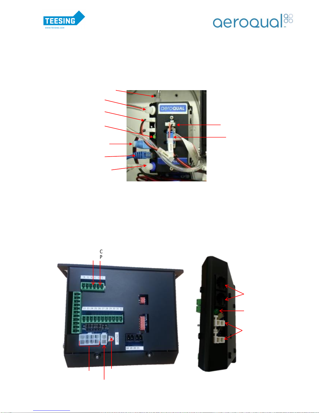
1.8.1. Profiler Pump Module
1.8.2. Nephelometer Pump Module
The Pump Module is split into two sections:
1. The electronics
2. The pump and pneumatics
The functionality of the electronics module can be seen below:
Status LED
12VDC Power
Connectors
RJ45 Connectors for
RS485 bus
Connection
80180 engine
PM Fibre Span Switch
Inlet Heater
Connection to
Purge Pump
Connection to
Sample Pump
Termination Dongle
Purge line
Exhaust line with
flow adjuster
Inlet heater connector
RS232 connector from
optical engine.
12VDC power
connection
RS485 bus cable
Sample line
Power on LED
WWW.TEESING.COM | +31 70 413 07 50

Page | 14
Note: The jumpers in the current module should be positioned as shown in the previous image.
The pump and pneumatics are easy to access for servicing and replacement:
1.9. Electrical Connections
Pin 1 = 12V (blue)
Pin 2 = GND (white)
Purge Pump
Pin 3 = 12V (red)
Pin 4 = GND (black)
Sample Pump
Purge
Pump
Sample Pump
Exhaust Line
Sheath Air Out
Sample In
Connection to
electronics module
(Pin 1 to 4)
Embedded PC
Compressor
SM
Module
Gas
Module 1
TMS
Heater
Power supply 1
12V DC
Mains Power in (Section 2.2.1)
12V DC
Power
Signal
Mains
Power
TMS = Thermal Management
System
Power supply 2
12V DC
AC
SWITCH
BOX
BOX
DC
SWITCH
BOX
Cabinet
Air in
Blower
TMS
fan
T/RH
Sensor
Gas
Module 2
WWW.TEESING.COM | +31 70 413 07 50
Page | 15
RS485 Bus
The two wire RS485 bus connections are made using 20 cm CAT5 cables between the sensor modules
12 VDC Power Bus
All modules inside the AQM 65 operate from the 12VDC power. The power is supplied by a daisy chain
of black and red cables. To turn off the 12VDC power to the upper cabinet release the fuse holder.
Status LED
Each module includes a status LED which indicates that the electrical status of the module is
functioning correctly. It does not indicate the calibration status of the module.
a) Continuous on indicates correct electrical functionality
b) Slow flash (1 second) indicates warm up period
c) Fast flash (0.2 seconds) sensor failure
d) LED not on indicates no power to module.
e) The System Manager LED is a special case. This flashes to indicate RS485 bus traffic.
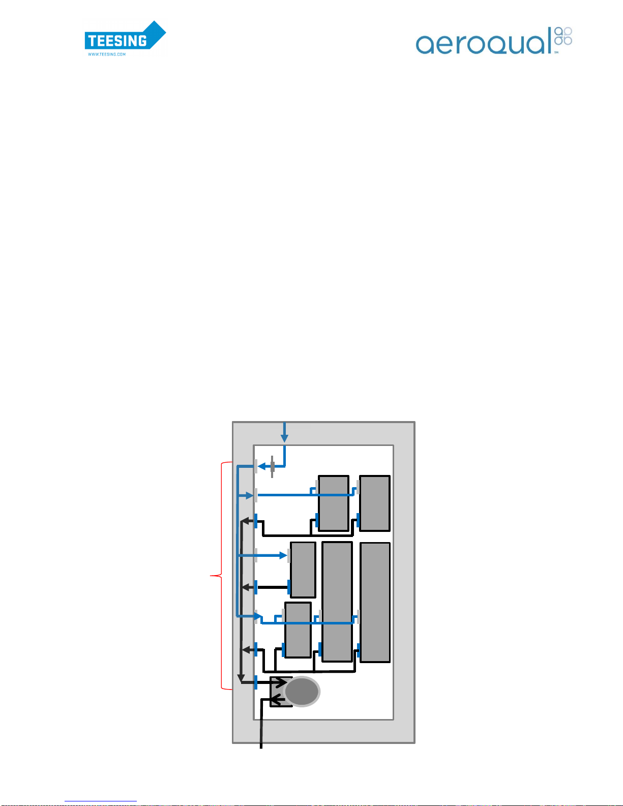
1.10. Pneumatic Connections
The sample gas passes into a PFA manifold behind the left hand side wall and is distributed to the
sensors. The gas modules sample via a single pump located in the bottom left of the enclosure. The
pump is easily accessible for maintenance. The sample inlet tubing is PFA tubing which is inert and
smooth walled. The module exhaust tubing is Tygon 3603 PVC tubing.
Note: The ports on the manifold which are not used must be capped off to prevent leaks.
Note 2: The blue lines represent the sample flow and the black lines represent the exhaust flow.
Exhaust
Inlet
PFA manifold
Pump
Module
Module
Module
Module
Module
Module
WWW.TEESING.COM | +31 70 413 07 50

Page | 16
An adjustable bypass valve is included between the vacuum and pressure side of the pump. This is to
allow an adjustment to be made to the module flow rates and to relieve the excess pressure placed on
the pump when only one or two modules are installed.
The total sample flow rate will be dependent on the number of gas sensor modules in the AQM. All
module flows are controlled by critical orifices located within the sensor modules. See Section 8.3.3.for
expected flow rates.
2. Set Up
The purpose of this section is to enable the user to correctly assemble, configure and commission their
AQM 65 prior to field installation.
2.1. Unpacking
a) Examine the Shockwatch label on the side of the shipping box. If the indicator is red do not
refuse shipment. Make a notification on delivery receipt and inspect for damage. If damage is
discovered, leave item in original packaging and request immediate inspection from carrier
within 15 days of delivery date (3 days international).
b) Verify the serial number label on the documentation matches the serial label on the AQM
(located on inside of enclosure).
c) Verify that all components have been shipped as per the packing slip. Contact your Distributor
or Aeroqual if you suspect any parts are missing.
d) Unpack the AQM.
e) Remove all internal shipping/packaging material from the AQM enclosure.
f) Retain the packaging.
Note: Always transport the AQM in the three piece aluminum skins with foam packing provided
to avoid breakages. Wrap all peripheral assemblies in their original packaging also. The AQM is
a sensitive instrument and should be transported with care.
2.2. Assembly
2.2.1. Connect Mains Power
Caution: The high voltage mains supply must be wired by a certified electrician in
compliance with local electrical regulations.
To connect the mains power follow the steps below:
1. Unscrew the front panel of the AQM 65 TMS cassette. There are 4 screws at each corner that
need to be removed to allow the front panel to slide off. The door must be open to access these
screws.
2. Unscrew the lid of the terminal box to access the wiring.
WWW.TEESING.COM | +31 70 413 07 50

Page | 17
AC Switch Box
3. The mains electrical cable needs to be fed through the gland at the base of the instrument into
the terminal box.
Note 1: The AQM65 can be placed flat on its back to access the gland
Note 2: Ensure the nut gland and rubber plug have been fed through the electrical cable before
feeding the cable through the gland at the base of the instrument
4. Wire the cable to the terminal block
5. Tightly screw the gland at the base of the instrument to secure the cable in place and create a
waterproof seal.
6. Replace the lid of the terminal box and the front panel of the TMS cassette.
Connected by local
electrician:
Brown = Live
Blue = Neutral
Yellow/Green = Ground
Connected by Aeroqual (Do
not remove)
Mains electrical cable from
base of instrument
WWW.TEESING.COM | +31 70 413 07 50

Page | 18
2.2.2. Connect Inlet System
Once the AQM 65 has been wired the inlet
system needs to be connected before the
instrument is turned on. The inlet system consists
of an inert fluoropolymer and glass inlet with
mesh fitting which is designed to prevent
unwanted materials, such as water and dust,
being drawn into the instrument. The inlet pipe is
connected to the top of the AQM 65.
A 5/8 spanner is required to securely tighten the
¼” stainless steel compression fitting.
If an external filter holder has been purchased with the AQM 65, remove the mesh fitting from the inlet
pipe and screw the filter holder into place. The arrow on the filter holder should be pointing upwards.
2.2.3. Assembly of heated inlet for PM/Profiler (Optional)
If the AQM 65 is configured with a Nephelometer or Profiler the heated inlet needs to be connected prior
to the instrument being turned on.
Parts List:
A. Inlet Tube/Heater including power cable
B. Sharp Cut Cyclone (if fitted)
C. TSP Inlet
i. Connect parts A, B and C
ii. Open door of enclosure and remove protective cap from the optical engine
A
B
C
Protective
Cap
Mesh
fitting
External
filter holder
WWW.TEESING.COM | +31 70 413 07 50

Page | 19
iii. Insert Inlet Tube Assembly through base mount and fix the three mounting screws
Note 1: Ensure the power cable is fed through the inlet hole when connecting the inlet
iv. Connect power to Inlet Tube/Heater inside the enclosure
2.2.4. Connect third party sensors (Optional)
Third party sensors such as the Vaisala Weather Transmitter WXT520 or Met One MSO are connected
to the unit via the external glands located on the right hand side of the enclosure. Feed the cable
through the glands and connect to the auxiliary module using the instructions in Section 1.5.
Note: Turn off the AQM 65 before plugging in any external third part sensor.
2.3. Connect to the AQM 65
Aeroqual Connect is the standard user interface which comes with the AQM instrument and allows the
user to be connected directly to the AQM instrument. It can be accessed via WiFi, Ethernet or a cellular
modem. The on-board computer has an Ethernet output for direct wired connection. . Alternatively,
connection can be made over WIFI by connecting to the AQM network (Access point mode), a local
network (Client mode) or via a modem.
Mounting
Screws
Power cable from
heated inlet
WWW.TEESING.COM | +31 70 413 07 50

Page | 20
2.3.1. Initial Connection via Access Point Mode
The default setting of the instrument when first purchased will be to connect to Aeroqual Connect via
access point mode. Access point mode allows connection to the AQM via the AQM network signal
which will show up on a laptop, tablet or smart phone within range. This type of connection will most
commonly be used when working on the AQM in the field. However, it will also be used to initially
connect when the instrument first arrives.
Connecting by this mode will mean the user’s device is connected via WIFI directly to the AQM. There
will be no internet connection on the user device when using this option. To connect you will need to
select the AQM WIFI network and enter the password.
Note: The default password will be “Aeroqual”.
Once a WiFi connection has been made Aeroqual Connect can be accessed via the PC browser by
entering the IP address 10.10.0.1 in the address bar. The login screen below will then be displayed.
1. An Aeroqual Connect login name and password will be provided when Aeroqual Connect is first
2. Once you have logged in the homepage will be displayed.
Note 1: Different applications will appear depending on the user accessibility configured for
your account.
Note 2: See Section 3 for more connection options
AQM Network
Signal
WWW.TEESING.COM | +31 70 413 07 50
Other manuals for AQM 65
1
Table of contents
Other Aeroqual Measuring Instrument manuals


Popular Measuring Instrument manuals by other brands


Tektronix
Tektronix TTR500 series manual

Mobeye
Mobeye ThermoGuard CM2200 user manual

Silva
Silva Alba Windwatch user guide

Critical Environment Technologies
Critical Environment Technologies YES IMS Operation manual

Exotek Instruments
Exotek Instruments MC-160SA user manual

Milwaukee
Milwaukee Smart Monitoring System SMS110 user manual


