Aeroquip ProCrimpT 1390 User manual
1
Aeroquip ProCrimp 1390 Crimp Machine
© Aeroquip Corporation 1996
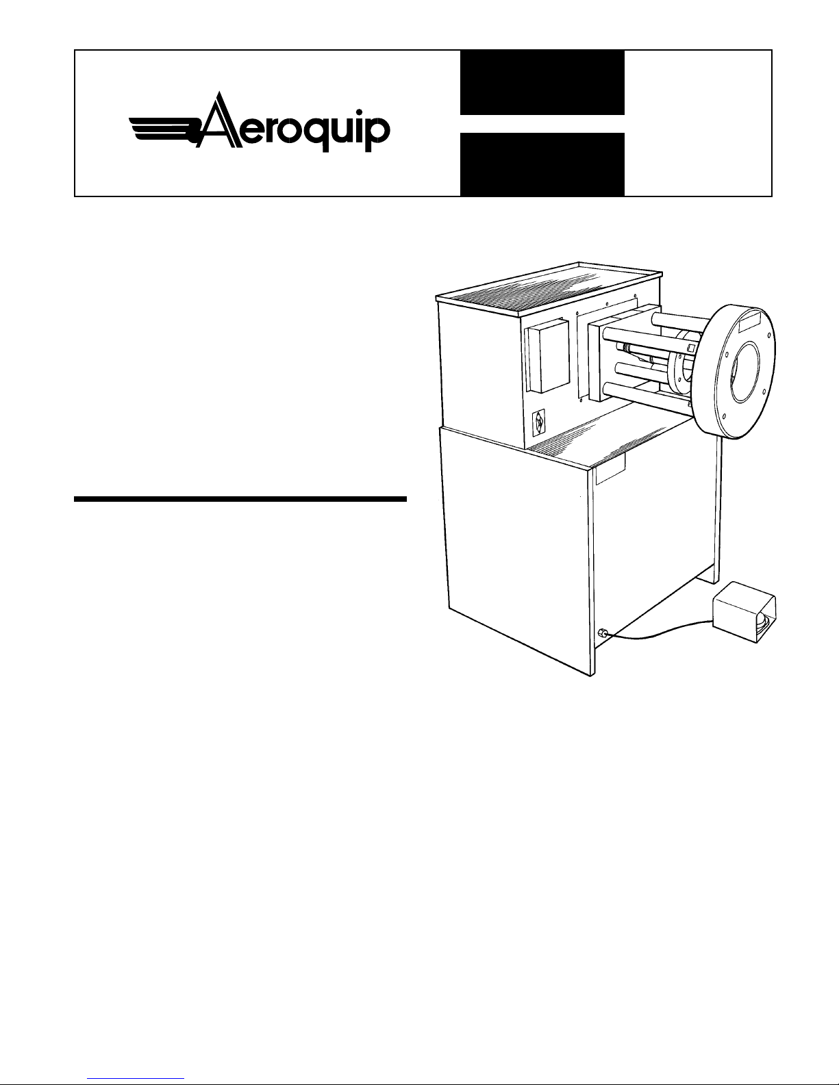
Aeroquip
ProCrimpTM
1390
Crimp Machine
Operator’s
Manual
Table of Contents
Safety Instructions .................................................... 2
Specifications ............................................................ 3
Accessories............................................................... 3
Setup and Installation ............................................... 3
Operating Instructions
Loading and Unloading Die Cages ................... 4
Operating the Keypad ..................................... 4-5
Entering a Number into the Display .................. 5
Storing a Number from the Display ................... 5
Recalling a Preset into the Display ................... 5
Programmable Retract Stop ..................................... 5
Adjustable Back Stop ............................................... 5
Crimping Procedures ................................................ 6
Calibration ................................................................. 7
Maintenance
Intervals .............................................................. 8
Machine Maintenance Procedures .................... 8
Die Cage Maintenance Procedures................... 8
Troubleshooting Tips ................................................ 9
Crimp Machine Parts Breakdown ..................... 10-12
Die Cage Parts Breakdown .................................... 12
Electrical Schematics ........................................ 13-14
Hydraulic Schematic ............................................... 14
FT1390-500
www.TheCatalogRoom.com Purchase at: www.EatonProducts.com

2
Aeroquip ProCrimp 1390 Crimp Machine
© Aeroquip Corporation 1996
WARNING
Failure to follow Aeroquip process and
product instructions and limitations could
lead to premature hose assembly failures, resulting in
property damage, serious injury or death.
Aeroquip fitting tolerances are engineered to match
Aeroquip hose tolerances. The use of Aeroquip fittings
on hose supplied by other manufacturers and/or the use
of Aeroquip hose with fittings supplied by other manu-
facturers may result in the production of unreliable and
unsafe hose assemblies and is neither recommended
nor authorized by Aeroquip.
Read and understand the operator’s manual before
attempting to operate any equipment.
Aeroquip hereby disclaims any obligation or liability
(including incidental and consequential damages) arising
from breach of contract, warranty, or tort (under
negligence or strict liability theories) should Aeroquip
hose, fittings or assembly equipment be used with the
hose, fittings or assembly equipment supplied by
another manufacturer, or in the event that product
instructions for each specified hose assembly are
not followed.
Safety Instructions
1. PREVENT UNAUTHORIZED OPERATION. Do not per-
mit anyone to operate this equipment unless they have
read and thoroughly understand this manual.
2. WEAR SAFETY GLASSES.
3. AVOID PINCH POINTS. Do not rest your hand on the
crimp ring. Keep your hands clear of all moving parts.
Do not allow anyone, other than the operator, close to
the equipment while it is in operation.
4. MAINTAIN DIES WITH CARE. Dies used in the FT1390
crimp machine are hardened steel, offering the best
combination of strength and wear resistance for long
life. Hardened dies are generally brittle, and care should
be taken to avoid any sharp impact. Never strike a die
with a hardened instrument.
5. USE ONLY SPECIFIED AEROQUIP PRODUCTS. Make
hose assemblies using only Aeroquip hose and fittings
specified for this assembly equipment.
6. VERIFY CORRECT CRIMP DIAMETERS. Check and
verify correct crimp diameters of all fittings after crimp-
ing. Do not put any hose assemblies into service if the
crimp diameters do not meet Aeroquip crimp specifications.
7. Make sure all dies are completely in place and the cage
is positioned properly on the pressure plate.
8. DO NOT OVER PRESSURIZE. Do not exceed the 10,000
psi hydraulic pressure supplied to the machine. This setting
is preset at the factory and should not require adjustment.
NOTE: All components used to connect the pump and
crimp cylinder must meet the criteria set forth in Material
Handling Institute Specification #IJ100 for hydraulic jack-
ing applications.
9. DIE CHANGE. Do not insert/remove dies while the
power is on.
10. SECURE THE EQUIPMENT TO A STABLE WORK SUR-
FACE. Prior to operation, secure the crimp machine to a
stable work surface to prevent the equipment from tipping.
11. UNPLUG THE POWER SUPPLY WHEN NOT IN USE.
12. KEEP YOUR WORK AREA CLEAN. Cluttered areas and
workbenches invite accidents.
www.TheCatalogRoom.com Purchase at: www.EatonProducts.com

3
Aeroquip ProCrimp 1390 Crimp Machine
© Aeroquip Corporation 1996
Setup and Installation
1. Secure the Aeroquip ProCrimp 1390 crimp machine to
the floor using the holes provided in the corners of the
crimp machine base.
2. Remove the plug from the hydraulic reservoir vent port, and
replace it with the vent cap that is supplied with the unit.
CAUTION: Failure to do so will cause cavita-
tion and damage to the pumping mechanism.
Hand tighten the vent cap.
3 CAUTION: Provide electrical service with a
dedicated circuit (per the crimp machine elec-
trical requirements) in order to eliminate the
possibility of a low-voltage situation.
4. Never use an extension cord. Always plug the unit
directly into the power outlet.
Specifications
Electrical Requirements:
FT1390-115 ....... 110 to 120-Volt AC single phase 60 Hz
........................... circuit with a minimum of 20 amps
FT1390-23050 ... 208 to 230-Volt AC single phase 50 Hz
circuit with a minimum of 15 amps
Crimp Machine Dimensions:
Width ................. 29 inches
Depth ................. 28 inches
Height ................ 49 inches
Weight ............... 825 pounds
Production Capacity:
• All Aeroquip MatchMate Plus™braided and spiral
hose through -32 size
• Flat field crimp through -16
• Barrel field crimp through -20
• Flat single skive 1- & 2-wire braid crimp through -32
• Flat single skive 4-wire spiral crimp through -32
• Internal skive fittings
• Air conditioning hose fittings
• OTC flat crimp or OTC beer can crimp fittings
NOTE: A positive-stop backstop is required to crimp Aeroquip
2807, 2808, FC186, FC465, FC469 and FC505 hose styles.
Accessories
Crimp Die Cage Storage Cabinet
Aeroquip recommends that crimp die cages be kept free of
dust or dirt. An optional wall-mountable cabinet is offered
which has the capability to store nine crimp die cages.
Part Number ............................................................. FT1283
Die Cages
Part Number ........................................... FT1307-200-M070
........................................... FT1307-200-M090
........................................... FT1307-200-M120
........................................... FT1307-200-M150
........................................... FT1307-200-M180
........................................... FT1307-200-M210
........................................... FT1307-200-M240
........................................... FT1307-200-M280
........................................... FT1307-200-M320
........................................... FT1307-200-M370
........................................... FT1307-200-M420
........................................... FT1307-200-M465
........................................... FT1307-200-M520
........................................... FT1307-200-M550
........................................... FT1307-200-M570
........................................... FT1307-200-M630
........................................... FT1307-200-M690
Additional die cages are required for internal skive and spe-
cial application hoses.
.
www.TheCatalogRoom.com Purchase at: www.EatonProducts.com

4
Aeroquip ProCrimp 1390 Crimp Machine
© Aeroquip Corporation 1996
Operating Instructions
Loading and Unloading Die Cages
To load the die cage, press and hold the RETRACT switch
until the crimp cylinder reaches the “full retract” position
and stops. The die cage may be inserted or removed in this
position. (See Figure 1.) NOTE: To minimize cycle time
during normal operation, the Aeroquip ProCrimp 1390 crimp
machine can be programmed to stop retracting before it
has fully retracted. This reduces the crimping cycle time.
The die cage may not be able to be removed. Pressing and
holding RETRACT will always bring the cylinder to the full
retract position. See instructions on Page 5.
CAUTION: Figure 2 shows a die cage that is
installed improperly. When inserted properly, the
cage is flush against the pressure plate. If the
die cage is at an angle to the pressure plate,
lift it up and realign properly.
Operating the Keypad (Figure 3)
1. The DISPLAY shows the three-digit setting that will
determine the crimp diameter. The DISPLAY number
itself is a relative number, not a crimp diameter. The
ratio of crimp diameter change to the DISPLAY change
is 1 to 1. For example, if you crimp a fitting at a setting
of 250, and the crimp diameter is .014 inch too large,
you will need to decrease the DISPLAY by 014 to
(250-014) = 236. A display of 236 should produce the
correct crimp diameter.
2. The STORE button is used to store the DISPLAY read-
ing in any of the 10 numbered keys. The green light
next to the STORE button will illuminate when you are
working in the STORE mode.
3. The ENTER button is used to put any three-digit num-
ber into the DISPLAY. The green light next to the EN-
TER button will illuminate when you are working in the
ENTER mode.
Figure 2
Figure 1
Figure 3
1 23
Store Display Enter
Number
Buttons
www.TheCatalogRoom.com Purchase at: www.EatonProducts.com

5
Aeroquip ProCrimp 1390 Crimp Machine
© Aeroquip Corporation 1996
4. The numbered keys have two functions:
a. In the ENTER mode, their numeric value is put into
the DISPLAY.
b. In the STORE mode, they act as 10 different memory
locations in which to store a DISPLAY setting.
Entering a Number into the DISPLAY
1. Turn the power control switch below the keypad to the
ON position. The DISPLAY will illuminate to show that
the power is on.
2. Press the ENTER button. (The green light next to the
ENTER button will illuminate.)
3. Press three number buttons. (If more than five seconds
elapse between pressing the number buttons, the DIS-
PLAY reverts back to its previous setting.) After the third
number is pressed, the DISPLAY will remain and the
green light next to the ENTER button will turn off.
4. The FT1390 is now ready to crimp to the DISPLAY setting.
Storing a Number from the DISPLAY as a Preset
1. Enter a three-digit number as described in the pro-
cedure above.
2. Press the STORE button. (The green light next to the
STORE button will illuminate.)
3. Press and hold down any one of the 10 numerical but-
tons for three seconds. (After three seconds, the green
light next to the pressed button will illuminate, indicating
that the DISPLAY has been stored to that button.)
Recalling a Preset into the DISPLAY
1. Make sure that the STORE and ENTER lights are off. (If
one is on, it will go off in five seconds if the keypad is left
untouched.)
2. Press the numeric button that has the stored setting for a
given hose and fitting style. That setting will then be
seen in the DISPLAY, and the light next to the numeric
button will illuminate.
Programmable Retract Stop
1. Using the Crimp/Retract switch, place the cylinder in the
position where you want it to stop during retraction.
2. Press and hold the ENTER button until the green light
next to the button turns off (approximately three sec-
onds). The cylinder will now automatically stop retracting
at this position until another position is set or until the
crimp machine is shut off.
NOTE: Pressing and holding the RETRACT switch will allow
the cylinder to fully retract. This will not change or erase the
programmable retract stop.
NOTE: Turning the crimp machine off and back on erases the
programmable retract stop position.
Adjustable Backstop (Figure 4)
1. Turn off the power to the machine.
2. Insert the die cage.
3. Loosen the thumbscrew on the backstop.
4. Place the fitting against the locator cone. Pushing it too
hard will compress the spring, which will affect the accu-
racy of the position.
5. Slide the backstop to the desired position. (For Match-
Mate Plus fittings refer to Figure 5.)
6. Tighten the thumbscrew.
7. Turn the power on.
Figure 4
➚
Backstop
www.TheCatalogRoom.com Purchase at: www.EatonProducts.com

6
Aeroquip ProCrimp 1390 Crimp Machine
© Aeroquip Corporation 1996
Crimping Procedures
Refer to the current Aeroquip Crimp Specifications bulletin
for complete and detailed crimp specification information
for each hose and fitting style.
1. Retract the cylinder by pressing the RETRACT switch
until the cylinder is fully retracted. Select the proper die
cage from the current Aeroquip Crimp Specifications
bulletin. Insert the die cage onto the pressure plate.
(See Figure 1.)
2. Press the proper PRESET button or key in a value to
the DISPLAY. (See Example.) MatchMate Plus and
MatchMate BLUE™ target setting charts are available
from Aeroquip.
3. Position the fitting in the crimp die cage according to the
corresponding figure in the current Aeroquip Crimp Speci-
fications bulletin. (A MatchMate Plus fitting is shown in
Figure 5.)
4. To crimp the fitting, press the CRIMP switch or footswitch.
The die cage will advance until the fitting is fully crimped
(Figures 6 & 7). It will then automatically begin to retract,
signifying that the crimp is complete. Release the crimp
switch or footswitch. The die cage will automatically re-
tract and stop at the “full retract” position or at the pro-
grammable retract position if it has been set.
HINT: Retraction can be halted at any point by
momentarily pressing the RETRACT switch or footswitch.
5. Verify the correct crimp diameter.
REMINDER: Full retraction is required for changing
die cages.
Figure 7Figure 5
Example:
Enter the number “500” into the DISPLAY, and start the
crimping process. If the dies crimp the fitting, measure
the crimp diameter and decrease the DISPLAY setting
by the same amount that you wish to decrease the
crimp diameter. If the dies don’t touch the fitting, lower
the DISPLAY setting by 050 to “450” and crimp the
fitting again. If that still isn’t enough, continue to reduce
the DISPLAY setting by 050 increments until the dies
make contact with the fitting. Then, measure the crimp
diameter and decrease the DISPLAY setting by the
same amount that you wish to decrease the crimp
diameter.
If a display setting of “250”–using GH793-8 hose
with TTC fittings–produces a crimp diameter of 1.004
inches, subtract the crimp specification (0.990 inches)
from the diameter that you measured (1.004-
0.990=0.014). Then, subtract “014” from the DIS-
PLAY setting (250-014=236), and change the
DISPLAY to “236.” Crimp the fitting again, and mea-
sure the crimp diameter. If the crimp diameter is still
too large, repeat this process.
Figure 6
Proper Crimping Position
for MatchMate Plus Fittings
Scribe
Line
➚
www.TheCatalogRoom.com Purchase at: www.EatonProducts.com
7
Aeroquip ProCrimp 1390 Crimp Machine
© Aeroquip Corporation 1996
Calibration
The calibration procedure below will calibrate the Aeroquip
ProCrimp 1390 crimp machine to the original factory set-
ting. While new machines are calibrated at the factory and
will be ready to use upon receipt, this procedure should be
followed if the crimp machine has been disassembled or
has had components replaced. The procedure requires the
use of an FT1307-200-M180 die cage, a 1SB4 socket (or
TTC-4 fitting), and a 1SB8 socket (or a TTC-8 fitting).
NOTE: While in the calibration mode, follow the instructions
precisely, and press the keys deliberately. If a mistake is
made, the calibration procedure must be started over by
turning the machine off and then on again.
1. Insert an FT1307-200-M180 die cage.
2. Press the STORE and ENTER buttons simultaneously, and
then release. Both button lights will now illuminate and will
remain lit until the calibration procedure is finished.
3. Input the value of “210” using the keypad.
4. Center a 1SB4 socket or TTC-4 fitting (without a hose)
in the die cage, holding the socket or fitting in place with
a pencil or other suitable tool. Crimp the socket by
pressing the crimp switch or footswitch until the ma-
chine retracts by itself, indicating a completed cycle.
Allow the die cage to retract to the “full retract” position.
5. Using a micrometer, measure the crimp diameter. The
preferred method is to use the average of the four pairs
of indentations.
6. Locate the crimp diameter in Table A, below. Using the
keypad, enter in the three-digit DISPLAY reading that
corresponds to the crimp diameter.
NOTE: If your crimp diameter falls between the numbers
shown in Table A, simply determine or interpolate the DISPLAY
reading, since the numbers are a direct ratio.
7. Input in the value of “610” using the keypad.
8. Center a 1SB8 socket or TTC-8 fitting (without a hose)
in the die cage, holding the socket or fitting in place with
a pencil or other suitable tool. Crimp the socket by
pressing the crimp switch or footswitch until the ma-
chine retracts by itself, indicating a completed cycle.
Allow the die cage to retract to the full retract position.
9. Repeat steps 5 and 6 at left, using Table B for the -8 socket.
10. After the three-digit DISPLAY reading in Step 9 is entered,
the machine will automatically exit the calibration mode.
Table A for -4 Table B for -8
Crimp Display Crimp Display
Diameter Reading Diameter Reading
0.670 170 1.070 570
0.680 180 1.080 580
0.690 190 1.090 590
0.700 200 1.100 600
0.710 210 1.110 610
0.720 220 1.120 620
0.730 230 1.130 630
0.740 240 1.140 640
Calibration Example:
Crimp a 1SB4 socket, and measure the four crimp
diameters around the socket. Let's say, for example,
that the diameters measure .692, .693, .694 and .694
inches. To obtain the average diameter, add the four
diameters, and divide that sum total by 4.
(.692+.693+.694+.694) =2.773 = 0.69325 = 0.693
44
(round to nearest
thousandth)
Look at the crimp diameter column in Table A and
find your average diameter. If it falls between two
numbers, as this one does, interpolate the desired
setting. In this case, you would enter 193. If your
crimp diameter is .690, you would enter 190; if it is
.697, you would enter 197.
Crimp a 1SB8 socket, and measure the four crimp
diameters around the socket. This time, let's say that
the diameters measure 1.113, 1.115, 1.114 and 1.115
inches. Obtain the average diameter by adding the
four diameters and dividing that sum total by 4.
(1.113+1.115+1.114+1.115) =4.457 = 1.11425 = 1.114
44
(round to nearest
thousandth)
Look at the crimp diameter column in Table B and
find your average diameter. If it falls between two
numbers, as this one does, interpolate the desired
setting. In this case, you would enter 614. If your
crimp diameter is 1.110, you would enter 610; if it is
1.119, you would enter 619.
www.TheCatalogRoom.com Purchase at: www.EatonProducts.com
8
Aeroquip ProCrimp 1390 Crimp Machine
© Aeroquip Corporation 1996
Maintenance Intervals
Die Cage Lubrication
Every 50 crimps............. Relube sliding surfaces of dies
Every 500 crimps .......... Remove old grease and relube
Every 1000 crimps ........ Die cage maintenance
(See below.)
Crimp Ring Maintenance
Every 500 crimps .......... Remove old grease and relube
Every 2000 crimps ......... Remove old grease, inspect for
wear or damage and relube if OK.
Cylinder Plate Bushing Maintenance
Every 2000 crimps ......... Remove old grease, inspect for
wear or damage and relube if OK.
Use NEVER•SEEZ lubricant (Aeroquip Part Number FT1092).
Maintenance Procedures
Machine Maintenance Procedures
1. Sliding surfaces must be kept free of dirt and other
abrasive materials.
2. All exposed black metal surfaces should be coated oc-
casionally with a light film of oil to prevent corrosion.
3. Periodically check the oil level in the fluid reservoir of
the hydraulic power unit. Maintain the oil level according
to the indicator on the top of the reservoir. Add ENERPAC
premium hydraulic oil as needed.
NOTE: Completely retract the crimp ring when checking
the oil level.
Die Cage Maintenance Procedures
1. Lubricate the die cage. For maximum service, die cages
require lubrication at 50-crimp intervals with NEVER•SEEZ
(Aeroquip Part Number FT1092). FT1092 is an eight-
ounce container that will provide sufficient lubricant for
about 5,000 crimps.
Periodically remove NEVER•SEEZ residue that has built
up on the sides of the dies and in the crimp ring during
the crimping process. Do not allow contaminated
NEVER•SEEZ to come into contact with the dies. (This
can cause dies to stick to the crimp insert.) NEVER•SEEZ
residue becomes contaminated with metal and plating
chips and airborne contaminants, which can cause pre-
mature wear of the dies and crimp ring.
2. Die cage maintenance should be performed at 1000-
crimp intervals or every six months, which ever occurs
first. Die cages should be free of grease and debris and
inspected for worn or damaged components.
a. The sliding surface of the dies should appear smooth
with no apparent galling. Galled dies must be re-
placed. Individual dies in a cage can be replaced
without replacing all eight dies.
b. Replace springs that show any sign of damage or
collapse such as those which are shorter than the
other springs.
c. The spring plate should appear smooth with no
apparent galling. Galled spring plates must be re-
placed.
d. Inspect remaining components, and replace those
that are badly worn.
Reassemble components, and liberally apply
NEVER•SEEZ to the die surface which slides along the
spring plate. Torque the die cage bolts to 50 in. -lbs.
Ensure that all dies slide in and out freely.
WARNING: Removal of the cylinder and hydraulic
power unit from a crimp machine that is not se-
cured to the floor will cause reduced stability.
www.TheCatalogRoom.com Purchase at: www.EatonProducts.com

9
Aeroquip ProCrimp 1390 Crimp Machine
© Aeroquip Corporation 1996
Troubleshooting Tips
Symptom Possible Cause Corrective Action
Pump will not start • No power or wrong voltage • Make sure that the unit is plugged in.
• Make sure that the power source is on.
• Make sure that the power voltage is correct.
• Check for loose wires on the circuit board.
• Check for loose wires on the CRIMP switch.
Motor stalls under load • Low voltage • Verify that the branch circuit conforms to the
electrical specifications on Page 3 of this manual.
• Remove any extension cords.
Electric valve will not • No power or wrong voltage • Check for loose wires on the circuit board.
operate • Low voltage • Check for loose wires on the CRIMP switch.
• Make sure that the power voltage is correct.
Pump fails to build • External leak in system • Wipe away spilled oil, and locate the source of
pressure • Internal leak in pump leak. If the hose assembly is leaking, tighten or
• Internal leak in valve replace it. If the pump or cylinder is leaking,
• Internal leak in system component refer to the ENERPAC Repair Parts Sheets.
Slight oil seepage of the cylinder is normal.
Pump builds less than • Relief valve set low • Refer to the ENERPAC Repair Parts Sheets for
full pressure • External system leak possible adjustment or leakage repair.
• Internal leak in pump
• Internal leak in valve
• Internal leak in system component
Pump builds full pressure, • Tie rods may be binding • Replace the tie rods.
but cylinder does not move • Flow to cylinder blocked • Refer to the ENERPAC Repair Parts Sheets.
Cylinder will not return • Valve malfunction • Refer to the ENERPAC Repair Parts Sheet for
• Restricted/blocked valve or cylinder repair.
• Tie rods may be binding • Replace the tie rods.
• Die cage may be binding • Check the die cage and crimp ring for damage,
and repair or replace them if necessary.
• Lubricate the die cage per the maintenance
procedures on Page 8.
• Lubricate the tie rod bushings per the
maintenance procedures on Page 8.
Crimp diameters change • Incorrect hose/fitting combination • Verify the correct hose/fitting combination.
• Incorrect die cage • Verify the correct die cage.
• Die cage or crimp insert damage • Repair or replace the damaged components.
• Transducer is loose • Tighten the transducer and brackets, and then
• Loose crimp machine components recalibrate them if necessary.
• External damage to crimp machine • Tighten any loose bolts or screws
• Insufficient lubrication on dies • Lubricate the die cage per the maintenance
procedures on Page 8.
• Lubricate the tie rod bushings per the
maintenance procedures on Page 8.
DISPLAY blinks • Loose or broken wires • Tighten any wires that may have become
loose on the circuit board, pump electrical
enclosure, or CRIMP switch.
If the symptom appears to be solely pump or cylinder related, refer to the ENERPAC Repair Parts Sheets.
Any electrical checks must be done by a qualified electrician.
Remember: The electric motor only runs during the
crimping process. The motor energizes when the crimp/
retract switch or footswitch is pressed and de-energizes
when the cylinder has retracted.
Refill oil reservoir with ENERPAC premium hydraulic oil only (ENERPAC P/N H-F-101).
www.TheCatalogRoom.com Purchase at: www.EatonProducts.com

10
Aeroquip ProCrimp 1390 Crimp Machine
© Aeroquip Corporation 1996
Detail Part Number Description Qty
1 1C02217GGG0310A Hose Assembly 2
2 FF2032T0606S 90°Adapter 2
(may have all 45°adapters)
3 FF2093T0606S 45°Adapter 2
4 FF9339-08-24S 1/2-13 X 1.50 SHCS 4
5 FT1289-2-2-14 Retaining Ring 1
6 FT1289-2-2-15 Crimp Ring Insert 1
7 FT1289-3-13 Push Rod 4
8 FT1289-3-15 Pressure Plate 1
9 FT1289-3-46 Plate 1
10 FT1289-3-60 Caution Decal 1
11 FT1289-3-62 Guard 1
12 FT1303-3-76 Shoulder Bolt 2
13 FT1330-3-64 Attention Decal 1
14 FT1330-3-68 Work Lamp 1
15 FT1330-3-7 Rubber Grommet 1
16 FT1340-2-2-19 Tie Bar 4
Detail Part Number Description Qty
Crimp Machine Parts Breakdown
➚
15
➚
48
44
➚
39
➚
56
➚
57
➚
17
➚
36
➚
42
➚
20
➚
(
19
➚
56
➚
34
47
49
OR
OR
➚
2
➚
1
➚
51
➚
38
➚
43
➚
51
➚
3
➚
35
28
➚
➚
44 48
➚
50
➚
58
17 FT1340-2-2-20 Nut 4
18 FT1340-2-2-23 Crimp Ring 1
19 FT1340-2-5-1 Motor Starter Switch 1
20 FT1340-3-2 Tray Matting (2 pieces) 1
FT1340-3-4 Backstop Assembly 1
(includes Details 22 through 27)
22 FT1340-3-4-1 Shoulder Bolt 1
23 FT1340-3-4-2 Spring 1
24 FT1340-3-4-3 Locator Plate 1
25 FT1340-3-4-4 Bronze Bushing 1
26 FT1340-3-4-5 Thumb Screw 1
27 FT1340-3-4-6 Locator Cone 1
28 FT1360-3-8 1/4-20 X .38 BHCS 4
29 FT1380-3-3 3-Position Switch 1
30 FT1380-3-6 Key Pad 1
31 FT1380-3-7 Electrical Enclosure 1
32 FT1380-3-18 #4-40x.188 lg. SHCS 4
➚
55
➚
40
➚
21
www.TheCatalogRoom.com Purchase at: www.EatonProducts.com

11
Aeroquip ProCrimp 1390 Crimp Machine
© Aeroquip Corporation 1996
100 Watt Maximum
13
➚
➚
41
➚
59 7
➚
➚
16
➚
26
➚
22
➚
27
➚
8
➚
4
➚
10
➚
18
➚
5
➚
6
➚
11
➚
52
➚
53
➚
9
➚
12
➚
23
24
➚
25
➚
➚
51
➚
31
➚
32
37
➚
➚
33
➚
29
➚
30
➚
46
➚
14
➚
54
Detail Part Number Description Qty
33 FT1380-3-31 Insulated Wire 3
34 FT1390-3-1 Hydraulic Power 1
Unit 115VAC 60HZ
35 FT1390-3-2 Hydraulic Cylinder 1
36 FT1390-3-3 Cylinder Adapter 1
37 FT1390-3-4 Control Card 1
38 FT1390-3-5 Transducer 1
(includes clips and rod adapter)
39 FT1390-3-6 Base (includes electrical box) 1
40 FT1390-3-7 Transducer Rod Extension 1
41 FT1390-3-8 Push Block 1
42 FT1390-3-9 Cylinder Mounting Plate 1
43 FT1390-3-10 Transducer Bracket 1
FT1390-3-11 Decal, Serialized (Not Shown) 1
44 FT1390-3-14 Compression Connector 3
45 FT1390-3-15 Compression Connector 1
46 FT1390-3-16 Foot Switch 1
Detail Part Number Description Qty
47 FT1390-3-17 Hydraulic Power 1
Unit 208-240VAC 60HZ
48 FT1390-3-18 Locknut 4
49 FT1390-3-19 Hydraulic Power 1
Unit 230VAC 50HZ
50 FT1390-3-6-2 Rear Panel 2
51 222003-1-8-6S #8-32 X .38 SHCS 8
52 FF9339-0108-06S #8-32 X .38 BHCS 2
53 FF90258-0110-06S #10-32 X .38 FHCS 2
54 FF9156-0110-08S #10-32 X .50 BHCS 2
55 FF9197-06-08S 3/8-16 X .50 SHSS 1
56 222003-6-12S 3/8-16 X 0.75 SHCS 10
57 222003-6-40S 3/8-16 X 2.50 SHCS 4
58 222003-8-56S 1/2-13 X 3.50 SHCS 2
59 222003-6-32S 3/8-16 X 2.00 SHCS 4
60 222003-1-10-6S #10-24 x .38 SHCS 2
FT1092 NEVER-SEEZ (not shown) 1
JA570 ProCrimp 1390 Decal (not shown) 1
JA146C Aeroquip Decal (not shown) 2
www.TheCatalogRoom.com Purchase at: www.EatonProducts.com
12
Aeroquip ProCrimp 1390 Crimp Machine
© Aeroquip Corporation 1996
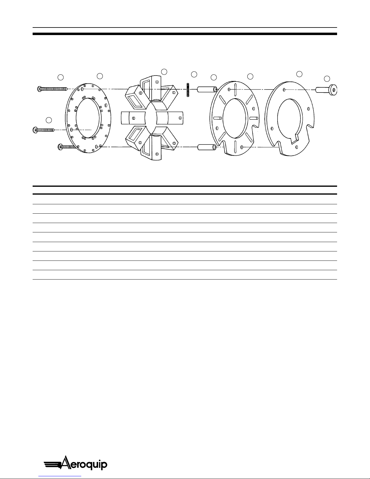
FT1307 Die Cage Parts Breakdown
Detail Qty Part Number Description
1 8 pc 21057-7 Roll Pin .25 dia x .62 long
2 8 pc FT1209-2-9-7 Spring
3 1 pc FT1307-2-9-3 Spring Plate
4 1 pc FT1307-2-9-4 Front Plate
5 3 pc FT1307-2-9-5 BHCS 5/16-18x2.56 long
6 4 pc FT1307-2-9-6 Spacer
7 1 pc FT1307-2-9-7 Nut
8 1 pc FT1307-2-9-8 Back Plate
9 1 pc FT1307-2-9-10 BHCS 5/16-18x3.00 long
18
7
5
➚
9
➚
4
➚
➚
2
➚
➚
63
➚
➚
➚
www.TheCatalogRoom.com Purchase at: www.EatonProducts.com

13
Aeroquip ProCrimp 1390 Crimp Machine
© Aeroquip Corporation 1996
Detaill Qty Part Number Description
1 3 pc FT1209-2-9-1 BHCS 5/16-18x3.90 long
2 1 pc FT1209-2-9-2 Front Plate
3 4 pc FT1209-2-9-3 Spacer
4 1 pc FT1209-2-9-4 Back Plate Assembly (Details 5 through 9)
5 1 pc FT1209-2-9-4-1 Back Plate
6 2 pc FT1209-2-9-4-2 Roll Pin .09 dia x .50 long
7 2 pc FT1209-2-9-4-3 Rod
8 2 pc FT1209-2-9-4-4 Spring
9 2 pc FT1209-2-9-4-5 Roll Pin .125 dia x .75 long
10 1 pc FT1209-2-9-5 Shoulder Screw
11 8 pc 21057-7 Roll Pin .25 dia x .62 long
12 1 pc FT1209-2-9-7 Spring
13 1 pc FT1209-2-9-8 BHCS 5/16-18x3.50 long
FT1209 Die Cage Parts Breakdown
➚
1
13
➚
2
➚
3
➚
8
➚
6
➚
7
➚
9
➚
10
➚
5
➚
4
OR
➚
11
➚
12
www.TheCatalogRoom.com Purchase at: www.EatonProducts.com

14
Aeroquip ProCrimp 1390 Crimp Machine
© Aeroquip Corporation 1996
Electrical Schematic for FT1390-115 (115V model)
Electrical Schematic for FT1390-230 (230V model)
www.TheCatalogRoom.com Purchase at: www.EatonProducts.com
15
Aeroquip ProCrimp 1390 Crimp Machine
© Aeroquip Corporation 1996
Electrical Schematic – Terminal Blocks and Pin Numbers
(115V and 230V models)
Terminal Pin
Block Number Voltage Wire Color Description
TB1 1 +12V AC Black From transformer
TB1 2 +0V AC White From transformer
TB1 3 None Green To earth ground
TB2 1 +4.04V DC Orange To transducer
TB2 2 +4.04 to 0.04V DC* Red To transducer
TB2 3 +0.04V DC Brown To transducer
TB2 4 +5V DC Red Crimp switch
TB2 5 0V DC White Switch common
TB2 6 +5V DC Red Retract switch
TB2 7 +5V DC Black Footswitch
TB2 8 0V DC White Footswitch common
TB3 1 +24V AC Blue To retract solenoid
TB3 2 +24V AC Orange To motor contractor
TB3 3 +24V AC Red To advance solenoid
*The voltage at TB2 pin 2 varies between 4.04V DC and 0.04V DC, depending on the position of the cylinder.
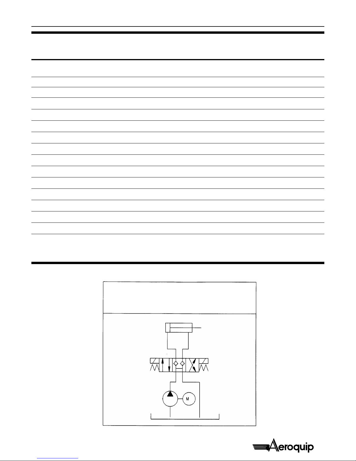
Hydraulic Schematic
SEQUENCE
1. Pump and extend solenoid on: Cylinder extends
2. Pump and retract solenoid on: Cylinder retracts
3. Pump and both solenoids off: Cylinder holds
www.TheCatalogRoom.com Purchase at: www.EatonProducts.com

16
Aeroquip ProCrimp 1390 Crimp Machine
© Aeroquip Corporation 1996
3-96 FT1390-500 Litho in U.S.A.
AMERICAS INDUSTRIAL DIVISION
1695 Indian Wood Circle
P.O. Box 700
Maumee, OH 43537-0700
Phone: 419-891-5100
Fax: 419-891-7890
http://www.aeroquip.com
Specifications subject to change without notice.
Aeroquip products are protected by patents internationally
www.TheCatalogRoom.com Purchase at: www.EatonProducts.com
Table of contents


