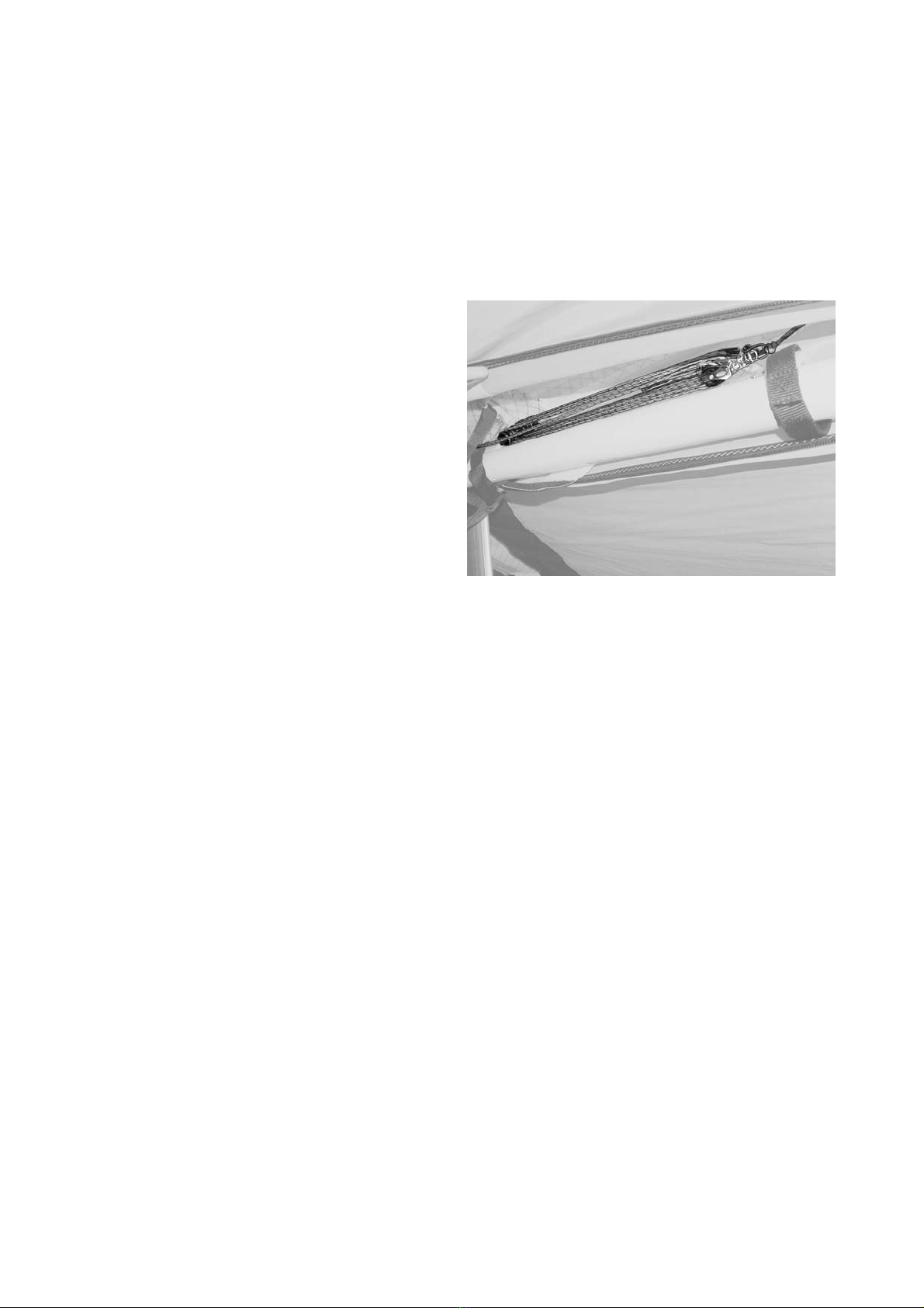
Aeros COMBAT-09 Application guide

HANG GLIDER
COMBAT-09
OWNER / SERVICE MANUAL
Size:__________________
Date of production:
___________________
Serial number:
___________________
Manufactured by:
AEROS Ltd.,
Post-Volynskaya St. 5.,
Kiev, 03061,
UKRAINE
Tel: (380 44) 455 41 18 Fax: (380 44) 455 41 16
E-mail: [email protected], http://www.aeros.com.ua
0

1

2
Combat Owner / Service Manual
Table of Contens
Introduction....…………………………………………..………….…..………………… 3
Technical information and operating limitations …...................…......…………….. 4
Combat reassembly after shipping procedure ...…..................…..……………..… 5
Combat breakdown procedure ...........................….…...........…...…...........…..…. 6
Combat set-up procedure ...........................…..…..............……................…….…. 6
Preflight procedure…………………………….………….………….…………….……. 11
Laying the glider down flat……………..……….….……………………….….……... 12
Launching and flying the Combat ..................…....................................……......... 13
Aerotowing ..………………………………………….…………………………………. 13
Using the VG system..............................................................................……....... 14
Landing the Combat ..............................................................................….…........ 14
Safety in turbulance…………………………………………………………………………15
Combat breakdown ................................…..............................................…......... 15
Removing the sail from the airframe and re-installing.........................…..….......... 17
Re-installing the sail on the frame..............……………………….........…..…......... 17
Combat stability systems.......................…..............................................….......... 18
Maintenance..………………..……….………………………………………...………. 19
Glider tuning............................................................…………………………..…….. 21
In closing - a few final words on your safety............................…....…................... 26
SCHEMES………………………………………………………………………………… 31

3
INTRODUCTION
Thank you for purchasing an Aeros glider.
The Combat L 09 (hereinafter Combat) hang glider is an advanced product of Aeros Ltd. It is aimed at improvement
of the modern competitive glider with very high performance combined with maximum safety and comfort.
Please read and be sure you thoroughly understand this manual before flying your Combat. Be sure you are
thoroughly familiar with the set up, break down, preflight and maintenance procedure as described in this manual.
If you have access to the Internet, please visit us regularly at http://www.aeros.com.ua
In case of any doubts or questions contact your local dealers or Aeros.
We wish you a safe and enjoyable flying career.
Aeros Ltd.

4
TECHNICAL INFORMATION AND OPERATING LIMITATIONS
The Combat has been designed for foot launched soaring flight. It has not been designed to be motorized, tethered,
or towed. However it can be towed successfully using proper procedures.
Flight operation of the Combat should be limited to non-aerobatic maneuvers; those in which the pitch angle will not
exceed 30 degrees nose up or nose down from the horizon, and the bank angle will not exceed 60 degrees.
Combat 09 14.9 14.2 13.7 13.2 12.8
Sail area, sq.m.(sq.ft.) 14.9
(160)
14.2
(153)
13.7
(145)
13.2
(142)
12.8
(138)
Wing span, m (ft) 10.7
(35.1)
10.7
(35.1)
10.35
(33.93)
10.35
(33.93)
10.0
(32.81)
Aspect ratio 7.7 8.06 7.9 8.05 7.8
Nose angle, º 129-131 129-131 129-131 129-131 129-131
Pilot clip weight optim., kg (lb) 100
(220)
95
(209)
85
(187)
80
(176)
75
(165)
Weight (without bags), kg (lb) 35.8
(79)
35.0
(78)
34.5
(77)
34.0
(75)
33
(73)
Number of upper sail battens 24 24 24 24 24
Number of bottom sail battens 6 6 6 6 6
Breakdown length, m (ft) 4.15/5.9
(13.4/19.3)
4.15/5.9
(13.4/19.3)
4.1/5.8
(12.8/19)
4.1/5.8
(12.8/19)
4/5.6
(13/18.4)
Tested load, G +6 / -3 +6 / -3 +6 / -3 +6 / -3 +6 / -3
Wind speed max, m/sec (mph) 12
(27)
12
(27)
12
(27)
12
(27)
12
(27)
Min. airspeed with optimal pilot clip
weight, km/h (mph)
29-31
(18-19)
29-31
(18-19)
29-31
(18-19)
29-31
(18-19)
29-31
(18-19)
Max. airspeed with optimal pilot clip
weight, km/h (mph)
110+
(69)
110+
(69)
110+
(69)
110+
(69)
110+
(69)
Min. clip pilot weight, kg (lb) 90
(198)
85
(187)
75
(165)
70
(154)
65
(143)
Max. clip pilot weight, kg (lb) 120
(265)
115
(254)
110
(243)
110
(243)
105
(231)
Aeros recommends that no attempt should ever be made to deliberately spin the glider.
The stability, controllability, and structural strength of a properly maintained Combat have been determined to be
adequate for safe operation when the glider is operated within the entire manufacturer specified limitations. No warranty
of adequate stability, controllability, or structural strength is made or implied for operation outside of these limitations.
Operation of the glider by unqualified pilots may be dangerous.
Operating the Combat outside of the above limitations may result in injury and death. Flying the Combat in the
presence of strong or gusty winds, or turbulence may result in loss of control of the glider, which may lead to injury and
death.
Do not fly in such conditions unless you realize and wish to personally assume the associated risks.
ATTENTION! We do not recommend using Combat for motorized and aerobatic flights.
It requires recommended pilot proficiency not less than pilot rating +40 hours or equivalent Safe Pro
rating to fly Combat.

COMBAT REASSEMBLY AFTER SHIPPING PROCEDURE
1. With the glider in the bag (4 meters long) lay the glider on the ground.
2. Unzip the bag. Undo the velcro straps. Remove the batten bag, the speedbar, the rear leading edge tubes # 3 and
winglets from the bag.
3. Unfold the sail along the leading edge to its full length. Attach the rear leading edge tubes # 3 to the front leading
edge tubes # 2 according to the marking (L-left, R-right, marks must be on top).
5
Working on one wing at a time, and working with the
appropriate leading edge # 3, fold the outer sprog, which
is attached to the rear leading edge, forward against the
rear leading edge. Slide the inboard end of the leading
edge tube # 3 into the sail.
Then slide the rear leading edge forward, allowing
the sprog end to come outside the sail at the access
zipper, and slide the rear leading edge into the front
leading edge.
Align the rear leading edge properly so that the sprog
bracket is on the inside of the leading edge, and slide
the rear leading edge forward, rotating as necessary,
until the button spring in the rear leading edge engages
securely into the holes in the front leading edge. When
the rear leading edge is fully engaged, you will not be
able to rotate it (Fig.1).
Fig. 1
4. Tighten the sail along the leading edge by putting the sail mount webbing into the slot in the end cap of the leading
edge # 3.
Note: the sail mount screws on the front part of the leading edge tubes # 1 must be unscrewed, otherwise the
excess sail tension will not allow tightening the sail.
The sail mount screws have to be screwed back after you accomplish all steps in section “Combat set-up
procedure” from item 1 through item 8.
5. Secure the sail mount webbing to the leading edge # 3 with the sail mount webbing velcro.
Note: When spreading the wings with the sail mount screws been unscrewed check that the sail mount webbing
is in proper position in the slot of the end cap of the leading edge # 3.
Fig. 2
6. Install the tip bags.
Put battens on top of the glider between Mylar
pockets in the front part of the glider.
Place velcro ties around the glider.
Put the speedbar and winglets between leading
edges in the rear part of the glider.
Put the glider bag back on and zip it up (Fig.2).

COMBAT BREAKDOWN FOR SHIPPING PROCEDURE
This process will basically be the reverse of reassembling after breakdown for shipping. Before beginning, read
through the section above on how to re-install the rear leading edges. While following the instructions below, refer to the
photos in the section above for reference, if necessary.
1. Lay the glider on the ground or floor, unzip the bag and remove the velcro ties. Remove the speedbar and winglets
from the glider. Remove the protection tip bags. The outboard sprog access zippers should be fully unzipped.
2. Check to see that the leading edges are marked “Left” and “Right”. If they are not, mark them with an indelible
marker.
3. Unscrew the sail mount screws from the leading
edges # 1.
Fig. 3
4. Undo the sail mount webbing velcro and remove the
sail mount webbing from the leading edges end caps. With
the outboard sprog folded towards the nose pull the rear
leading edge straight aft while pressing the button spring in
to disengage it from the front, and then slide it backward
carefully out of the sail. Tape or pad the edges of the front
end of the leading edge tubes # 3, and the rear of the
leading edge tubes # 2 to prevent sail damage during
transportation.
5. Carefully fold the rear of the sail over against the
front, place velcro ties around the glider and put on the
glider bag, turning the bag 180 deg (i.e. matching the front
part of the bag to the rear part of the glider) (Fig.3).
6. Zip up the glider bag zipper.
COMBAT SET-UP PROCEDURE
1. Lay the glider on the ground, with the bag zipper up, with the bag at right angle to the wind.
2. Undo the zipper, remove the speedbar and winglets from the glider.
3. Remove the speedbar from the bag, spread the uprights. Install the speedbar so that the offset of the speedbar is
directed forward in the direction of flight. Attach the speedbar using the quick-pins. Pass the VG-rope through the cleat;
make a knot on the end of the rope (Fig.4).
Fig. 4
4. Flip the glider upright on the control bar. Try to set the
basebar on level ground. Remove the glider bag and all
velcro ties. Remove the batten bag with the battens from the
front part of the glider. Spread the wings almost all the way,
so that the sail is a little sagged and the glider is resting on
the wing tips and on the keel tube.
5. By lifting up and back on the nose batten strings, push
the nose battens fully back into the sail so that the batten tips
rest on top of the keel tube (Fig.5).
Fig. 5
6

6. Attach the ring of the bottom front wires to the hook on the bottom nose plate(Fig.6).
7
Fig. 7
Fig. 6
7. Turn the hang point spreader bar perpendicular to the keel tube (Fig.7).
Close the central access zipper.
Fix the Velcro straps behind the
hang loop.(Fig.8)
Fig. 8
8. Remove the battens from the batten bag, and check each batten for symmetry against the corresponding batten
from the other wing. Align the battens at the nose, and at about the 60% chord point as shown. There should not be any
deviation of more than 3mm (1/8’’) from one batten to the other along the full length of the battens.
Aeros convention is that green (blue) marked battens go in the right wing and red marked battens in the left.
Battens are numbered from the center outwards, and the longest batten in a Combat is designated as the "# 1"
batten.
Install the cambered top surface battens in the sail, leaving out the shortest four on each side for now.
Fig. 9
Install the lever batten tips into the hem of the trailing
edge. At each batten, make sure the opening in the
underside of the trailing edge hem is spread to accept the
tab on the batten tip. Make sure the tab slides fully into the
hem (Fig.9).

To open or close the batten tip lever press firmly on the undersurface of the tip lever to disengage or engage it
(Fig.10).
Fig. 10 a Fig. 10 b
Fig. 11
Insert the battens carefully so as to minimize stress
and wear on the sail (Fig.11).
Never insert or remove top surface battens with the
cross-bar tensioned (except for up to the last four on each
side) and never insert or remove battens with heavy wind
pressure on the top of the sail or in any condition which
causes the battens to slide with great resistance in the
pockets.
Fig. 12
9. Spread the wings all the way and check all cables for
any twisted thimbles or tangled cables. At the rear of the
keel find the shackle of the sweep wire. Pull the shackle
out the rear end of the keel pocket, and check that the
sweep wire is not wrapped around the keel. Attach the
shackle of the sweep wire to the hook on the keel tube
(Fig.12).
An in-flight disengagement of this attachment
will cause a complete loss of structural support of
the glider and a total loss of control. Never attach
the pull handle of the shackle to the hook, even
temporarily.
10. Remove the protection bags from the wing tips and install the last four outboard top surface battens.
8

11. Install the tip battens (Fig.13):
- bend the tip batten with the angle approx. 60 degrees;
- install the batten into the sail with the bend directed to the wing tip;
- install the flat end of the batten into the angle of the sail tip;
- straighten the batten little bit and guide another end of the batten onto the leading edge batten hook;
- push the bend towards the keel section and gently straighten the batten completely.
9
Fig. 13 Fig. 14
12. Install the bottom surface battens (Fig.14).
13. The next step is to deploy both the inboard sprogs and the outboard sprogs and secure them in position. Before
doing so, working through the sprog access zippers, preflight the following items (Fig.15) :
Internal ribs to confirm that they are fully zipped up.
The sprog hardware, and the sprog cable attachments at both ends of each sprog cable.
Fig. 15 b
Fig. 15 a
To deploy and secure each sprog, swing the sprog away from the leading edge and align it in the center of the rear
end of the sprog access zipper.

Fig. 16
Fully close the sprog access zipper and this will secure
the sprog in the proper position underneath the transverse
batten and capture it in position (Fig.16) .
14. Install the nosecone taking care to align it so that it
lies flat on the top and bottom of the sail (Fig.17) .
Fig.1
7
Don’t fly without the nosecone!
15. Attach plastic winglets. Put front part of the winglet
between the sail and the outer part of the leading edge
tube (Fig.18) .
Fig. 18
Put the winglet tightly inside the sail, fixing it with
velcro.
16. Zip up the center sail zipper.
17. Do a complete preflight inspection of the glider (see
the Section “Preflight procedure”).
10

PREFLIGHT PROCEDURE
Conduct a complete preflight inspection of the glider, checking all assemblies, which have not already been checked.
Every bolt, nut, pin, safety ring, and fastener of any kind should be checked during every pre-flight. A full pre-flight
inspection should precede every flight you make, not just the first flight of the day.
Carefully check the entire length of the leading edge pocket to insure that the mylar insert is lying flat in the pocket. If
any section of the mylar is folded under, de-tension the crossbar, remove the batten closest to the area of distortion, and
unfold the mylar.
Take your time and inspect entire glider!
Fig. 19
Along the left leading edge
Open the main sprog access zipper and look
inside, making sure that the crossbar / leading edge
junction is assembled properly and safely secured
with the nut and the safety ring, side wires are
properly secured between the crossbar and the
leading edge plate, that the thimbles are not cocked
on the tang (Fig.19).
Check that the sail is not caught on the crossbar
end, or on any of the hardware
Remember to close the access zipper.
At the left wingtip
This procedure is better to perform before plastic winglets have been installed.
Look into the sail from the wing tip. Tip folded batten
must be rested on the batten stop. The washout tip must
be installed. Check for any evidence of dents, deep
scratches, cracks or bends in the LE tube.
Fig. 20
Be sure that the sail mount webbing is properly
installed in the end cap slot and safely and correctly
secured with the Velcro around the leading edge (Fig.20).
Along the trailing edge, left wing
Check that there are no tears in the sail material along
the trailing edge.
Check that all battens are properly secured.
Check that the outboard and inboard sprogs are properly secured in position supporting the transverse battens, and
that the sprog access zippers are properly closed. With the VG set tight, the sprog paddle slides forward on the
transverse batten. Make sure that at VG full tight the rear end of the paddle does not slide past the rear edge of the
transverse batten, or the system could malfunction.
Check that the bridles are properly engaged.
From the rear keel
Check that the sweep wire is tight and secured on the hook on the keel tube. Check the proper alignment of the VG
ropes – they must not be twisted.
Check the rear wires / keel tube junction. The assembly must be connected with the pin and secured with the safety
ring.
Along the trailing edge, right wing: Same as for the left wing.
11

At the right tip: Same as for the left tip.
Along the right leading edge: Same as for the left leading edge.
Under the glider at the control bar:
Sight down the down tubes, making sure that they are straight.
Do not fly with bent down tubes!
Check the cables at the control bar corners, making sure there are no kinks or twisted thimbles. Check for proper
installation of all nuts and safety rings at the control bar corners.
Fig. 21
Unzip the center zipper.
Check the sweep wire for wear where it passes around
hang point channel.
Check that the routing of all VG ropes and pulleys is
clear and straight (Fig.21).
Check the VG operation - the pull should be light initially, becoming harder as the VG tight limit is reached. The return
on release should be smooth.
With the VG set tight, the sprog paddles slides forward on the transverse batten. Make sure that at VG full tight the
rear end of the paddles does not slide past the rear edge of the transverse battens, or the system could malfunction.
Check the crossbar center plates assembly including the sweep wire/X-bar junction, all bolts are in places, secured
with nuts.
Also, visually inspect the crossbar by sighting along the length of the crossbars looking for any evidence of damage.
Check the control bar apex bracket hardware, including the clevis pin safeties, the control bar top plug bolt and nut.
Check the main and backup hang loops, pins and safety rings, bolt and nut, that they are properly installed in the
proper position and that they are in good condition.
LAYING THE GLIDER DOWN FLAT
Once you have the glider set up, it can be laid down flat on the ground.
1. Remove the nose cone from the nose.
2. Release the front wires from the nose hook.
3. Lay the glider down with nose into the wind.
4. Take a keel tube with a hand near the trailing edge and put the keel tube approx. 0.5 m up. Release the sweep
wire from the hook on the keel tube to loose a tension of bottom side wires.
Reverse this procedure to set the glider upright again.
12

13
LAUNCHING AND FLYING THE COMBAT
Before launching, hook in to the glider and do a careful hang check. We recommend that you hang as close to
the base tube as possible - this will give you lighter control pressures and better control in both roll and pitch.
1. If the wind is more than 25 km/h or gusty you should have an assistant on your nose wires on launch, and, if
necessary, an assistant on one or both side wires. Make sure all signals are clearly understood. Do a hang check
immediately prior to launch. The angle at which you hold the glider should depend on the wind speed and slope of the
terrain at launch; you want to achieve a slight positive angle of attack at the start of your run.
2. Run aggressively on launch and ease the bar out for lift off.
3. The flying characteristics of the Combat are typical of a high performance flex wing. Make your first flights from a
familiar site in mellow conditions to give you time to become accustomed to the glider.
4. We recommend that you take-off with VG off or approx. 1/4 on.
5. Do not take off if the sail is wet, especially the leading edge, as the stall speed will increase significantly. Always
fly with a dry sail!
6. For the same reason take special care to avoid ice covering the glider, particularly the leading edge in
wintertime.
Warning: It is important that you do not take off with VG on more then ½ length of VG rope. The
glider with VG more than ½ on becomes easier to stall and the roll response gets longer. With low
speed during take off it can lead to unintended stall.
SPEED TO FLY
The range of trim speed for the Combat with VG off is 33 - 35 km/h (21-22 mph). The speed bar position in front of
the pilots face corresponds to this range.
With the VG on the trim speed for the Combat is 40 – 45 km/h (25-28mph) depending on sprog setting. The base bar
position opposite the pilot’s neck or little bit lower corresponds to this range. The roll pressure increase significantly and
the roll rate becomes significantly slower with the VG full on.
Never fly your Combat when its trim speed with VG on more than 50 km/h (31mph) – the glider becomes
pitch unstable and dangerous to fly.
The Combat speeds up to 110 km/h (69 mph), being essentially roll neutral, with no tendency to yaw. The pitch bar
pressure decreases with the VG on, being light when flying close to the trim speed, but progressive and consistent,
constantly increasing when the speed increase.
AEROTOWING
Special care must be taken in any form of towing.
We recommend that the VG be set to 1/4 - 1/3 on prior to launch. This provides the best qualitative flight
characteristics for flying in formation with the tug at normal aerotow speeds
Fix the excess VG rope on the control frame so it will not interfere with the construction of the cart during
take off. Make sure that all the harness ropes are hidden inside the harness and will not get tangled on the cart
during take off.
If possible, it is best to adjust the keel cradle on the cart to re-set the glider to the proper angle of attack. For Combat
gliders the best angle of the keel tube in relation to horizon is approx. 18 - 20 deg.
If it is not possible to re-adjust the cart, recognize the launch will be more demanding, and more dangerous, as the
glider will have an increased tendency to leave the cart at a lower speed, where lateral control is reduced, and the
tendency to come off the cart with one wing low is increased. To some degree, this can be compensated by pulling
forward through the control bar to position the base tube below your shoulders, and holding tight to the hold down rope.
This will cause the glider to raise the keel as it begins to develop enough lift to lift out of the cart. At that point, and not
before that point, you can release the rope and ease your weight aft to fly the glider off of the cart. Be prepared to pull in
once clear of the cart if necessary so as not to climb more quickly than the tug.
Once clear of the cart and in the position behind the tug, use firm lateral movements of short duration for roll and
directional control in order to stay in the position behind the tug. Do not move to one side of the bar and wait for the glider
to respond - this will lead to over control and being out of position, and may lead to roll / yaw oscillations. It is better to
"bump" the glider firmly in the direction of the desired correction and then return to center. If you need more correction,
bump again. In pitch, stay on top of the situation and be as aggressive as necessary to keep the tug on the horizon.

USING THE VG SYSTEM
The Combat VG system uses a reduction system of pulleys between the central part of the crossbar and the hang
point tower channel to enable a wide VG range. The change in airframe nose angle from VG loose to tight is over 2
degrees. Tightening the VG increases the spanwise tension which the airframe places on the sail, reducing the spanwise
twist and the sail elasticity. The result is an increase in L/D performance and a reduction in roll control authority and roll
control response.
The VG is activated by pulling on the VG rope and then moving the rope to set the rope in the cleat. The
recommended procedure for increasing VG tension is to grasp the rope firmly at the cleat, and pull straight along the
basebar.
VG full loose is for maximizing roll control authority and roll rate.
Between VG full loose and VG one half, the glider retains good lateral control authority and response.
Tighter than VG one half, the glider’s roll pressures increase significantly and the roll rate becomes significantly
slower. Tight VG settings are recommended for straight line gliding, or for flying in smoother conditions when well clear of
both the terrain and of other gliders. The stall characteristics of the Combat at tighter VG settings are more abrupt and
less forgiving and the glider is more susceptible to spinning. Full breaking stalls and accelerated stalls at tighter VG
settings are not recommended.
LANDING THE COMBAT
Under ideal conditions, landing approaches are best done so as to include a long straight final into the wind at a
speed above best L/D speed. In a very limited field, or a field which slopes slightly downhill, when landing in light wind,
you may need to make your final approach at a slower speed, perhaps as slow as minimum sink, in order to be able to
land within the field.
In winds of less than 5 km/h (3 mph), if the landing area slopes down hill at more than 10:1, you should seriously
consider landing downwind and uphill; or crosswind, across the slope. Landing attempts, which require slow speed
approaches, maneuvering around obstacles or into a restricted area, or downwind or crosswind landings are not
recommended for pilots below an advanced skill level.
We recommend that you make your approach with the VG set between full loose and 1/2 on. A full loose VG setting
will reduce glide performance, making it easier to land on a target or within a small field. It will also ensure maximum
control authority during the approach, and especially when flying very slowly on final. At VG full loose, however, there is
some loss of aerodynamic efficiency and flare authority, For this reason, in very light winds, at higher wing loadings or at
higher density altitudes, it is recommended that a setting of VG 1/3 – 1/2 ore more be used. A full loose VG setting will
also increase the glider’s roll sensitivity, and some pilots have had difficulty with roll / yaw oscillations on final. The best
way to avoid this is to fly your entire approach at a constant airspeed, and to control your touchdown point by making
adjustments to the shape of your pattern. You should choose your approach speed based on the amount of wind and
turbulence present - in stronger wind and more turbulent air, fly faster. In any case, however, try to fly a constant airspeed
throughout the approach.
Once established on a straight final approach, with wings level and flying directly into the wind, you should fly the
glider down to where the basetube is between 1 and 2 m (3-6 ft) off the ground. At this altitude, let the control bar out just
enough to “round out” so that your descent is arrested and your flight path parallels the ground. The remainder of your
approach will consist of bleeding off excess speed while paralleling the ground and keeping the wings level and the nose
pointed in your direction of flight until it is time to “flare” for landing.
Fig. 22
Prior to the landing flare your body position should be
generally upright, but slightly inclined forward, with your
head and shoulders forward of your hips and your legs and
feet trailing slightly behind.
Many pilots make the mistake of trying to get too
upright at this stage of the landing, which actually reduces
your flare authority and makes it harder to land on your
feet. Your hands should be at shoulder width and shoulder
height on the uprights (Fig.22).
You should be relaxed, with a light grip on the bar, and
your weight should be fully supported in your harness and
not at all by your arms. (If your harness does not allow you
to hang in the proper semi-upright landing position “hands
off,” without supporting your weight on the control bar, you
will have a lot more difficulty making good landings).
We wish you many happy landings!
14

SAFETY IN TURBULANCE
A hang glider is a tailless aircraft and therefore its pitch stability is limited compare to the conventional aircraft. One of
the main design goals of the Combat 09 was to maximize pitch stability with a strong rigid sprog and dive sticks system
and compensated sprog system. After installing the tail on the Combat 09, pitch stability has greatly increased, allowing
even to lower sprogs settings keeping required pitch-up moment. However, there is still remains the risk of a tumble if
extreme turbulence is encountered, and it is important that the pilot understands ways to minimize this risk.
Many tumbles have happened because of the loss of airspeed due to turbulence. When the glider hits the surge of lift,
its nose raises, and even when the pilot holds the control bar in right position, the glider will climb and loose airspeed
quickly – that’s a moment when the tumble can occur, especially if sudden sink or rotating air is encountered. Therefore it
is important to maintain sufficient airspeed in turbulence and quickly react to bring the glider back to a normal flying
attitude, picking up the lost airspeed.
It is very important that the pilot hold the speedbar tight and close to the chest or just below the chest. If sudden
weightless or negative G situation occurs, the pilot should stay as close to speedbar as possible with his chest, keeping
a forward center of gravity, which greatly aids in producing a quick glider recovery.
A loose VG settings, due to the sprog compensator system, produce stronger positive pitch moment at negative angles
than tight VG setting. Therefore, it is necessary to release the VG completely or to ¼ VG when expecting a strong
turbulence. While in turbulence make sure you keep a very firm grip on the speedbar and do not sacrifice this strong grip
to release the VG. It is best to wait for a safe moment and then release.
FLYING IN RAIN
It is strongly advised to avoid flying in rain, as the stall characteristics of the glider change due to rain drops on the
leading edge. If rain is encountered in flight, keep the airspeed well above stall, especially near the ground and avoid any
turns close to the ground. At landing make final approach at higher speed than normally and be ready to flare
aggressively as son as the wing begins to stall. In no circumstances take off when your glider is wet.
COMBAT BREAKDOWN
15
loop out of the slots in bottom surface. Unzip the bottom
battens except the top
bat
ings in parallel to the keel tube. Take care
tha
Fig.24
Break down of the glider is the reverse of assembly.
1. Start with the VG set full loose. Remove the
nosecone. Remove any instruments.
2. Remove the undersurface battens. Unzip the sprog
access zippers all the way to the leading edge end of the
zippers and put out the inboard and outboard sprogs.
Remove the tip folded battens and the four shortest
battens from the outboard section of the sail. Roll the
outboard section of the sail and put the outboard wing tip
bags on (Fig.23).
3. De-tension the crossbar sweep wire and let the
wings fold in slightly.
4. Open the Velcro behind the hangloop and take the hang
surface central zipper and take the protecting pads sewed on the sail out so that they protect the sail from contact with
the control bar apex fittings (Fig.24).
Fig. 23
5. Remove the remaining
tens #1. Put the battens into the batten bag.
6. Pull the w
t the shackle of the crossbar sweep wire doesn’t
get caught when entering into the sail!
ires at the nose plate.7. Detach the front w

16
8. Fold the wings all the way in to the keel pulling the
sail over the
top of the leading edges. At each wingtip, remove the tip
cover bag. At this time you should be able to dismount the
front ends of the root battens from the keel tube. Install the
protective pad and sock over the rear wire junction pin and
the rear end of the keel.
9. Fold the sprogs against the leading edge towards the
tip. Make sure the sprog zippers are fully open.
10. Pull the sail out away from the keel until it is even
on top and bottom. Roll the sail gently and carefully,
parallel to the trailing edge of the front and then outboard
portion of the sail.
Try to roll the sail in such a way that the leading edge
portion remains as smooth as possible. Do not attempt to
stuff the sail between the Mylar pocket and the leading
edge tube at any point where you feel resistance, and do
not attach the velcro ties so tight so as to induce creases in
the Mylar or leading edge sail material (Fig.25).
11. Working from the trailing edge, roll the sail tightly to
the leading edge, and install the tip cover bags.
12. Secure the sail with the velcro sail ties. The first
velcro tie is installed by passing it over the top of the keel
tube just near the Crossbar-LE tube junctions, and then
installing it around the glider leading edges (Fig.26).
13. Place the bag with battens on the nose section along the keel, put the nose cone under the front velcro ties.
Secure the sail with remaining sail ties.
14. Install the glider bag. Flip the glider over onto the ground. Detach the basebar and place it between the leading
edges in the bag provided. Place winglets next to the basebar.
15. Fold up the control bar and install the control bar
bag, lay it down against the keel. Undo the velcro, which
was done first, reach it out to free the keel tube and install
it again around both leading edges with the control bar
inside. Bring all wires forward along tubes and place
downtubes inside the folded sail (Fig.27).
16. Zip up the glider bag.
The glider is ready for transportation.
Fig. 25
Fig. 26
Fig. 27

17
EMOVING THE SAIL FROM TH
ng the sail. Please read all the instruct
ve tarp or be extremely careful not to scrape y
bar protecti
other similar height support under the nose of the glider.
el.
. Dismount the downtube fitting-side wire connections, remove the side wires and pass them through the holes
inside of the sail.
original order so that it doesn’t get lost. All disassembled
the proper order and orientation.
. Slide the sail slightly forward and get the nose of t
ow slide the complete frame out through the open center zipper. If y
is hanging up.
re
t.
d p
. Fold and pack up the sail carefully if you plan to ship it in
you want done, your name and a phone number.
RE-INSTALLING THE SAIL ON THE FRAME
rted in the pocket.
folds in the Mylar insert, especially at the tips. Make sure
the Mylar wraps in the proper direction to follow the sail around the leading edge as it enters the pocket.
. Install the transverse battens in the sail.
. Position the sail on the floor with the keel pocket facing down and the wings folded over so that the leading edges
lie lying on top.
g edges installed.
e sail doesn’t get caught on to them during installation.
e plate facing up and with the rear end of the leading edges at the nose of the
sail. Slide the frame into the sail through the open bottom surface zipper, making sure that the leading edges of the frame
pass properly into the leading edge pockets of the sail and don’t get caught at the rear of the bottom surface near the
root. As you feed the frame slowly into the sail don’t forget to insert the keel into the keel pocket of the sail. Check
periodically to see that none of the hardware is snagging on the sail or internal sail ribs.
. Make sure you untie all sprogs from the leading edges and get them out of the sail through the sprog access
zip
RE AIRFRAME AND RE-INSTALLING
Many maintenance and repair procedures will require the
instructions when removing and reinstalli
removal of the sail from the frame. Please follow these
ions for each operation before beginning.
). Make sure the surface is clean. If it is abrasive, you should
our sail.
er bag. Untie the velcro ties, remove the basebar, winglets,
on bag.
m the sail. Dismount the sail from the front leading edge by
bing velcro and remove the sail mount webbing from the
e rear part of the keel tube. Detach the rear cables from the
tube. Unbolt the hang point tower with a spreader bar and a
SAIL REMOVAL
You will need an unobstructed area 2 m by 10 m (6x30 ft
either put down a protecti
1. Lay the glider on its back, unzip and remove the glid
battens and put them aside. Remove the control
2. Spread the wings slightly. Remove central battens fro
unscrewing the sail mount screw. Undo the sail mount web
plastic end at the rear leading edge.
. Put a chair or3
4. Remove the screw from the keel pocket webbing at th
keel tube.
5. Dismount the control bar apex assembly from the keel
hang loop from the keel tube and slide it forward, along the ke
6
Reassemble the hardware removed in its place in the
assemblies on the glider must be reassembled in
7he frame out through the nose hole of the sail.
ou encounter resistance, stop and find out what
move the Mylar inserts and the transverse battens. The Mylar
It helps to secure the opposite end of the sail to something
ull the Mylar straight out of the pocket.
for repair. Be sure to include written instructions of what
N
8. If you need to send the sail to the factory for repair,
insert is to remove from the front end of the Mylar pocke
solid, so that you can lay the leading edge out straight an
9
1. Install the Mylar inserts in the sail. Make sure you install them right side up; the slit edge is at the front and on the
bottom. The easiest way to install the Mylar insert is to push it into the pocket using a long lofting batten attached to the
end of the Mylar insert, which is first inse
You will have to stop from time to time to make sure the Mylar insert is properly lying flat in the pocket. Do not push
the Mylar insert too far into the pocket. Make sure there are no
2
3
along the length of the root line, with the Mylar pockets
4. The frame is most easily inserted with the rear leadin
5. Tie all sprogs down to the leading edges so that th
6. Position the frame with the top nos
7
pers.

18
ut trough the nose hole
of t
. Mount the sail mount webbing straps on the plastic caps of the rear leading edge tubes and secure them with the
elcro. (See the section at the beginning of the manual about re-assembly after shipping.)
ebbing with the screws to the front leading edges after you accomplish all steps
cedure as explained
earlier in this manual.
COMBAT STABILITY SYSTEMS
sdegree of stability in pitch:
dge.
ns and the internal fabric ribs, and adjustment of the internal velcro
sta
. Continue to slide the frame into the sail until you will be able to get the nose of the frame o8
he sail.
9
sail mount webbing v
10. Attach the keel retainer webbing strap to the keel tube with the screw.
11. Attach the hang point tower with the spreader bar and a hang loop to the keel tube. Check that the routing of the
sweep wire and all VG ropes around the spreader bar is right and clear.
12. Insert the side wires through the side wires holes out of the sail. Mount the side wires to the corresponding
downtube fittings, making sure that no cable is wrapped around a leading edge or crossbar, and that no thimbles are
cocked or twisted.
13. Attach the rear wires to the rear of the keel.
14. Set the glider up onto the control bar.
15. Spread the wings slowly and carefully, making sure that the sail rides forward as necessary at the nose without
catching.
Be careful: you can easily tear the sail open at the nose.
Note: When spreading the wings with the sail mount screws been unscrewed check that the sail mount webbing
is in proper position in the slot of the end cap of the leading edge # 3.
16. Finish the assembly of the glider completely according to the normal assembly procedures.
Note: Secure the sail mount w
in section “Combat set-up procedure” from item 1 through item 8.
17. Do a very careful and complete preflight of the glider according to the normal preflight pro
Several design features of the Combat determine the glider'
- The combination of wing sweep and spanwise twist.
- Reflex in the root section.
- Main (inboard) sprogs, and the height at which they and the transverse battens support the trailing edge.
- Outboard sprogs, and the height at which they and the transverse battens support the trailing e
- The shape of the preformed batte
attachments, which define the airfoil.
Correct attachment and proper adjustment of the inboard and outboard sprogs are critical to providing adequate
bility at low angles of attack, particularly those below the normal operating range.

19
A
tion contains a recommended schedule of periodic maintenance. None of the items in this section are a
substitute for the continual
worthiness
of t air or replace some part of your glider, feel
fre tems require attention and which may not.
Minor dents or dings in a non-critical
EV
oard sprogs, as described in the last section.
e pattern by more than 6 mm (1/4").
your batten pockets if you wipe each
batten with a rag before you install it in the sail.
any suspension system component that
shows any wear, and any cable that shows any kinks, wear, damage, corrosion, etc.
5. Inspect all bolts for tightness, all safeties for proper installation and possible damage. Inspect plates and
6. Inspect the sail for wear, tears, UV damage, loose stitching, etc.
e basetube pulley assembly, clean, lubricate with white grease, and re-assemble.
8. Lightly spray all zippers on the glider with silicone spray lubricant. Also spray your battens before you install
des of the batten pockets. Do not use any other type of lubricant. Wipe off
t attract dirt.
loaded heavily, it is possible
es may have been stretched.
EVERY
In addition to the normal six month serv
every part
me, inspect all of the batten pockets and batten pocket terminations.
3. Replace bottom side wires and hang loops.
5. Remove the transverse battens and inspect for damage.
M INTENANCE
This sec
and consistent practice of proper pre-flight inspections and immediate maintenance of any
items on the glider, which require it. Safety requires that your glider be fully airworthy for every flight. Nuts and bolts must
always be secure, safeties must always be in place, and damage to any part, which could compromise the air
he glider, cannot be tolerated. If you have a question about the need to rep
e to contact your dealer or Aeros directly. It is not always obvious which i
location on an airframe tube may not require any repair or maintenance. On the
other hand, a wire that has been kinked one time can fail very quickly after that, and should be replaced immediately.
We recommend that you have all maintenance work done by your Aeros dealer.
ERY SIX MONTHS
1. Check the adjustment of your outb
2. Check your battens on a flat level floor against the batten diagram provided, and correct any that deviate from
th
3. If you fly in a dusty or sandy environment, it will help to prolong the life of
4. Have a complete inspection performed on the glider and replace
fittings for damage, holes in tubes for elongation.
7. Disassembl
them in the glider to lubricate the insi
any excess silicone so that it does no
9. Inspect the sprogs, sprog hardware and sprog cables. If the sprogs have been
that the sprog tubes may have been bent, and the cabl
YEAR
ice items, also perform the following:
1. Have the sail completely removed from the frame, and disassemble all frame components. Inspect
of the glider for any damage or wear. Inspect the tubes for straightness and for signs of corrosion.
2. Anytime you have the sail off the fra
4. Replace the VG ropes.
Table of contents
Other Aeros Aircraft manuals

Aeros
Aeros Aeros-2 User manual

Aeros
Aeros PROFI TL Application guide

Aeros
Aeros Fox-16 Application guide

Aeros
Aeros COMBAT-C Application guide

Aeros
Aeros COMBAT 12T Application guide

Aeros
Aeros Combat 09 13.7 User manual

Aeros
Aeros TRIKE WINGS Stranger Application guide

Aeros
Aeros Discus 12 User manual

Aeros
Aeros PROFI Application guide

Aeros
Aeros Combat-GT Application guide

Aeros
Aeros Stalker Phantom User manual

Aeros
Aeros ANT User manual

Aeros
Aeros TARGET 13 User manual

Aeros
Aeros Stranger & Stream User manual

Aeros
Aeros Vitamin User manual

Aeros
Aeros Still TL Application guide

Aeros
Aeros SkyRanger User manual

Aeros
Aeros Aeros-2 User manual

Aeros
Aeros Stealth 14 KPL 2 User manual

Aeros
Aeros Still 17 User manual