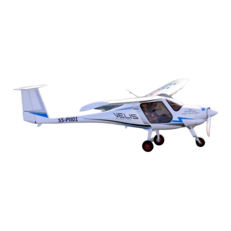
Pipistrel Virus 912 S-LSA Glider User manual

SERIAL NUMBER: 0359
REGISTRATION: N66PV
4/25/2011
AIRCRAFT OPERATING INSTRUCTIONS
Pipistrel Virus 912 S-LSA Glider
PIPISTREL LSA s.r.l.
Via Aquileia 75
34170 Gorizia, Italy, EU

AIRCRAFT OPERATING INSTRUCTIONS –VIRUS 912 S-LSA GLIDER
Page 1
TABLE OF CONTENTS PG
1. Purpose: 5
2. General Information: 5
2.1 Read this before your first flight! 5
2.2 Manufacturer. 5
2.3 Warnings, cautions, and notes. 5
2.4 Revision tracking, filing, and identifying. 6
2.5 Online updates, service notice tracking. 6
2.6 Schematics of Virus 212 S-LSA Glider. 8
3. Aircraft and Systems Descriptions: 9
3.1 Operating weights and loading (occupants, baggage, fuel, ballast). 9
3.2 Propeller. 10
3.3 Fuel and fuel capacity. 10
3.4 Oil. 10
3.5 Engine. 10
4. Operating Limitations: 11
4.1 Stalling speeds at maximum takeoff weight (VS, VS0, and VS1). 11
4.2 Flap extended speed range (VS0 to VFE). 11
4.3 Maximum maneuvering speed (VA). 11
4.4 Never exceed speed (VNE). 11
4.5 Maximum aerotow speed (VT). 11
4.6 Maximum winch tow speed (VW). 11
4.7 Maximum landing gear extended operating speed (VLO). 11
4.8 Never exceed speed (VNE). 11
4.9 Crosswind and wind limitations for takeoff and landing. 11
4.10 Load factors. 11

AIRCRAFT OPERATING INSTRUCTIONS –VIRUS 912 S-LSA GLIDER
Page 2
4.11 Prohibited maneuvers. 11
5. Weight and Balance Information: 12
5.1 Installed equipment list. 12
5.2 Center of gravity (CG) range and determination. 13
6. Performance: 14
6.1 Gliders: 14
6.1.1 Crosswind and wind limitations for takeoff and landing. 14
6.2 Powered Gliders: 14
6.2.1 Takeoff distances. 14
6.2.2 Rate of climb. 14
6.2.3 Climbing speeds. 14
6.2.4 Maximum RPM. 14
6.2.5 Time limit for the use of takeoff power. 14
6.2.6 Fuel consumption and total usable fuel volume. 14
6.2.7 Crosswind and wind limitations for takeoff and landing. 14
6.2.8 Speeds for extracting and retracting powerplant. 14
7. Emergency Procedures: 15
7.1 Engine Failure: 15
7.1.1 Engine failure during takeoff run. 15
7.1.2 Engine failure immediately after takeoff. 15
7.1.3 Engine failure in flight (forced landing). 15
7.2 In-flight start. 16
7.3 Smoke and Fire: 16
7.3.1 Fire on the ground. 16
7.3.2 Fire during takeoff. 16
7.3.3 Fire in flight. 16

AIRCRAFT OPERATING INSTRUCTIONS –VIRUS 912 S-LSA GLIDER
Page 3
7.3.4 Smoke in Cockpit. 17
7.4 Landing emergencies: 17
7.4.1 Emergency landing (landing out). 17
7.4.2 Precautionary landing. 17
7.4.3 Landing with a flat tire. 17
7.4.4 Landing with defective landing gear. 17
7.4.5 Water landing (ditching). 18
7.5 Spin Recovery. 18
7.6 Other Emergencies. 18
7.6.1 Stall Recovery. 18
7.6.2 Vibration. 18
7.6.3 Carburetor icing. 19
7.6.4 Icing, pneumatic instrument failure. 19
7.6.5 Bird strike. 19
7.6.6 Structural failure. 19
7.6.7 Electric failure. 19
7.6.8 Use of GRS whole plane rescue system. 20
8. Normal Procedures: 20
8.1 Preflight check. 20
8.2 Powered glider normal procedures: 27
8.2.1 Ground engine starting. 27
8.2.2 Taxiing. 28
8.2.3 Normal takeoff. 29
8.2.4 Engine extraction and retraction. 31
8.2.5 Best rate of climb speed (VY). 31
8.2.6 In-flight starting of engine. 31

AIRCRAFT OPERATING INSTRUCTIONS –VIRUS 912 S-LSA GLIDER
Page 4
8.2.7 In-flight shutdown of engine. 31
8.2.8 Ground shutdown of engine. 32
8.3 Cruise. 32
8.4 Approach 32
8.5 Normal landing. 33
8.6 Information on stalls, spins, and any other useful pilot information. 34
9. Aircraft Ground Handling and Servicing: 38
9.1 Servicing fuel, oil, and coolant. 38
9.2 Towing and tie-down instructions. 39
10. Required Placards and Markings: 42
10.1 Airspeed indicator range markings. 42
10.2 Operating limitations on instrument panel, if applicable. 42
10.3 Passenger Warning—“This aircraft was manufactured in accordance 42
with Light Sport Aircraft airworthiness standards and does not conform to standard
category airworthiness requirements.”
10.4 “NO INTENTIONAL SPINS,” if applicable. 42
10.5 Empty weight. 42
10.6 Maximum takeoff weight. 42
10.7 Maximum and minimum weight of crew. 43
10.8 Seat for solo operations of two seated gliders. 43
10.9 Allowable baggage weight. 43
10.10 Placards. 44
11. Supplementary Information: 45
11.1 Familiarization flight procedures. 45
11.2 Pilot operating advisories. 47
12 Maintenance Manual—Maintenance manuals containing routine, inspection, and repair maintenance
procedures for the aircraft, engine, and propeller, are provided under separate cover.

AIRCRAFT OPERATING INSTRUCTIONS –VIRUS 912 S-LSA GLIDER
Page 5
1. PURPOSE. To provide a standard instruction for the safe and efficient use of this Pipistrel Aircraft. By
combining a comprehensive instruction which describes Systems, Performance, Procedures, and
Limitations, this Instruction will provide the owner/pilot with the knowledge required to safely share the
passion of flight for many years.
This aircraft was built In accordance with the specifications of ASTMs F 2564, 2279, 2295, 2316, and 2483.
Additionally, we have used a power plant which complies with ASTM F 2339. Every Pipistrel LSA Glider is
accompanied by an Aircraft Operating Instruction (AOI). The content and format herewith is defined by
F 2564. Additions to F 2564 standards format are included wherever necessary to adequately describe
the safe operation of the aircraft. All flight speeds are given in terms of calibrated airspeeds (CAS),
unless otherwise noted. All specifications and limitations are determined from the specification F 2564.
Capacities, Dimensions, and Performance Measures are framed in terms commonly used in the American
Market. Although US temperatures are normally measured in degrees Fahrenheit, this instruction will
use degrees Centigrade, now commonly used in the US, to avoid confusion with instruments that display
temperatures in degrees Celsius/Centigrade.
2. GENERAL INFORMATION.
2.1 Read this before your first flight! Every pilot must understand the capabilities and
limitations of this light sport glider. The AOI must be read thoroughly. Pay attention to the pre-
flight and daily checks. Maintenance instructions for the aircraft are given in a separate
Maintenance Manual. For maintenance of the Rotax® engine, emergency parachute system and
other installed equipment refer to the original manufacturer´s manuals. Flying the Virus, like any
other motor glider, must include planning for a safe landing due to the possible loss of the engine
power at any time.
This Pipistrel Virus is designed for and capable of day and night VFR flight. Because of its cruising
speed and range, flight into vastly different weather patterns and meteorological conditions can
occur. The entry into bad weather with IFR conditions with VFR aircraft is extremely dangerous.
As the owner or operator of an aircraft you are responsible for the safety of your passenger and
yourself. Do not attempt to operate your Virus in any manner that would endanger the aircraft,
the occupants, or persons on ground.
2.2 Manufacturer.
PIPISTREL LSA s.r.l.
Via Aquileia 75
34170 Gorizia, Italy, EU
2.3 Warnings, Cautions, and Notes.
WARNING!
Disregarding the following instructions leads to severe deterioration of flight safety and
hazardous situations, including such resulting in injury and loss of life.
CAUTION!
Disregarding the following instructions leads to serious deterioration of flight safety.
AIRCRAFT OPERATING INSTRUCTIONS –VIRUS 912 S-LSA GLIDER
Page 6
NOTE:
An operating procedure, technique, etc., which is considered essential to emphasize.
2.4 Revision tracking, filing, and identifying. Pages to be removed or replaced in the Aircraft
Operating Instructions are determined by the Log of Effective pages located in this section. This
log contains the page number and revision level for each page within the AOI. As revisions to the
AOI occur, the revision level on the effected pages is updated. When two pages display the same
page number, the page with the latest revision shall be used in the AOI. The revision level on the
Log Of Effective Pages shall also agree with the revision level of the page in question. Alternative
to removing and/or replacing individual pages, the owner can also print out a whole new manual
in its current form, which is always available from www.pipistrel.eu. Revised material is marked
with a vertical double-bar that will extend the full length of deleted, new, or revised text added
to new or previously existing pages. This marker will be located adjacent to the applicable text in
the marking on the outer side of the page. The same system is in place when the header, figure,
or any other element inside this AOI was revised. Next to the double-bar, there is also a number
indicative to which revision the change occurred in. A list of revisions is located in section 2.5
below.
2.5 Online updates, service notice tracking. To log into the Owner’s section, receive relevant
updates and information relevant to Service/Airworthiness, go to: www.pipistrel.eu and log in
the top right corner of the page with:
Username: owner1
Password: ab2008
Index of revisions
The table below indicated the Revisions, which were made from the original release to this date.
Always check with your registration authority, Pipistrel USA (www.pipistrel-usa.com) or Pipistrel
LSA s.r.l (www.pipistrel.eu) that you are familiar with the current release of the operation-
relevant documentation, which includes this POH.
Designation
Reason for Revision
Release date
Affected pages
Issuer
Original
/
25 October, 2010
/
Tomazic,
Pipistrel LSA
s.r.l.

AIRCRAFT OPERATING INSTRUCTIONS –VIRUS 912 S-LSA GLIDER
Page 7

AIRCRAFT OPERATING INSTRUCTIONS –VIRUS 912 S-LSA GLIDER
Page 8
2.6 Schematics of Virus 912 S-LSA Glider.(dimensions in feet or inches)
13.4 ”
46.1 ”
43.1 ”
71.7 ”
22.4”
63.4 ”
43.3 ”
39.4 ”
9 ‘ 1.5 ”
18 ’ 9.6 ”
11 ‘ 0.7 ”
24.8”
36.2 ”
60 ”
43.3”
21’ 3.7”
6
8
.
6
”
64.6”
44.5”
68.6”
40’ 10.6”
10.4”
10’ 6.4”
29.1”

AIRCRAFT OPERATING INSTRUCTIONS –VIRUS 912 S-LSA GLIDER
Page 9
3. AIRCRAFT SYSTEMS AND DESCRIPTIONS.
Pipistrel Virus S-LSA Glider is intended for recreational, sport, cross-country, and training; but it is not
approved for aerobatic operation.
The Virus is a single engine, carbon, Kevlar, and glass aircraft with two side-by-side seats. It is equipped
with a tricycle gear undercarriage with a steerable nose wheel and toe brakes. The fuselage is a carbon
shell with carbon/Kevlar seats integrated. The wing is a mono-spar construction with a sandwich skin
composed of two layers of fiberglass with a foam core. Control surfaces are of the same construction.
The aircraft is controlled by a dual push-pull control system. The ailerons and elevator are controlled by
the control sticks located between the pilot's and co-pilot’s legs. The rudder is controlled by the rudder
pedals, flaps and spoilers are operated by control levers located between the pilots.
3.1 Operating weights and loading SN: 359.
empty weight
702.5 lbs (319.3 kg)
max. takeoff weight (MTOM)
1210 lbs (550 kg)
fuel capacity (full)
2 x 13 gal = 26 US gal (100 L)
fuel capacity (usable)
24.5 US gal (93 L)
max. fuel weight allowable
167 lbs (76 kg)
maximum useful load
508 lbs (231.1 kg)
minimum combined cockpit crew weight
119 lbs (54 kg)
maximum combined cockpit crew weight
519 lbs (227.3 kg)
luggage weight
55 lbs (25 kg) (80 lbs (40 kg) if GRS is removed)
WARNING! Should any of the above-listed values be exceeded, the others MUST be reduced in order to
keep MTOM below 1210 lbs (550 kg). Pay special attention to luggage weight as this is the only applicable

AIRCRAFT OPERATING INSTRUCTIONS –VIRUS 912 S-LSA GLIDER
Page 10
mass on the airframe that can cause the center of gravity to move out of range. Exceeding baggage
weight limits can shift the aircraft’s balance to the point where the flight may become uncontrollable!
NOTE:Weight and Balance information is found in paragraph 5 below.
3.2 Propeller. The Propeller, made by Pipistrel, is a fixed pitch, auto-feathering, two
bladed design, which is optimized for safe and efficient operation of your Pipistrel Touring
(Self Launch) Motor Glider. See Maintenance Manual for inspection, adjustment, and
servicing instructions.
3.3 Fuel and fuel capacity. Automotive Unleaded per ASTM D 4814, minimum octane 89
fuel may be used if it does not contain ethanol or special additives. 100LL may also be used.
For questions about additives, see Rotax Operators Manual.
Fuel is contained in two, extended range tanks, each with 13 gallon capacity (total 26 gallons)
of which 24.5 gallons useable.
Recommended fuel unleaded super, 89 octane, without ethanol or additives
Also approved fuel leaded or AVGAS 100LL*
* Use of leaded or even low-lead fuels may reduce engine life and oil and oil filter changes at
least every 50 hours becomes crucial for proper care of your engine.
WARNING! Use of fuel with alcohol content and/or other additives is not permitted.
3.4 Oil. API SJ SAE, 10W-50. Rotax 912 engine oil capacity is 3 quarts. For suitable oil types refer to the
original Rotax Operator’s Manual.
3.5 Engine.
Engine model: ROTAX 912 UL (80 HP) mfg: Bombardier-Rotax
Cylinder Head Temperature (CHT) oC : Minimum / Working /
Highest
80 / 110 / 120
Exhaust Gas Temperature (EGT) : Normal Range / Highest
650-885 / 900
Max EGT difference
30
Radiator water temperature range oC : lowest / highest
50 / 120
Engine Oil Temp oC : minimum / normal range / highest
50 / 90-110 / 140
Oil Pressure psi : minimum / maximum
14.5 / 87.0
Max RPM (5 min)
5800
Max Continuous power RPM
5500
Ignition - Magneto Check RPM
4000
Max single magneto drop RPM
300
NOTE: This data is relevant for the pilot. Consult Rotax engine manual for all other engine details.
Warning! Should the engine reading be outside of these parameters: do not take off; if in the air, land as
soon as possible! Always be prepared to respond to an engine failure.

AIRCRAFT OPERATING INSTRUCTIONS –VIRUS 912 S-LSA GLIDER
Page 11
4. Operating Limitations
4.1 Stall Speeds
4.2 Flap extended speed range (VSO and VFE): 36 kts –70 kts
4.3 Maximum maneuvering speed (VA): 76 kts
4.4 Never exceed speed (VNE): 120 kts
4.5 Maximum aerotow speed (VT): N/A
4.6 Maximum winch tow speed (VW): N/A
4.7 Maximum landing gear extended operating speed (VLO): N/A
4.8 Never exceed speed computation (VNE): 120 kts
4.9 Crosswind and wind limitations for takeoff and landing: 15 kts
4.10 Load factors.
Maximum positive wing loading: + 4G
Maximum negative wing loading: - 2G
NOTE: These values correspond to ASTM standards for LSAs. All parts have been tested to a safety
positive G factor of 1.875, meaning they were subjected to at least a load of plus 7.5 G
4.11 Prohibited maneuvers.
Aerobatics
Fully developed spins
Take off with less than 1.3 gallons of useable fuel
Flight with both cabin doors removed
Flight into known icing conditions
Flight into IMC

AIRCRAFT OPERATING INSTRUCTIONS –VIRUS 912 S-LSA GLIDER
Page 12
5. WEIGHT AND BALANCE INFORMATION.
5.1 Installed equipment list.
Nose wheel, steerable
Long Range Fuel Tanks, 26 gallons
Large Instrument Panel
Solid Luggage Compartment
Side baggage door
Ballistic Rescue System
Airspeed Indicator
Altimeter
Dynon 180 EFIS
Garmin GTX 327 Transponder
Variometer LS 160
Oil Check door
Auto feathering propeller
Pedal mounted toe brakes pilot & copilot
Fast mount engine cover screws
Leather interior Tan and Dark Red
Wings prepared plumbed for night lighting

AIRCRAFT OPERATING INSTRUCTIONS –VIRUS 912 S-LSA GLIDER
Page 13
5.2 Center of gravity (CG) range and determination.
a = 40.15”
c = 60”
Wfr = 107.2 lbs
Wm = 595.3 lbs
55 lbs
max
46”
Empty Weight
Wtot = 702.5 lbs
N66PV
Virus 912 S-LSA SN:
0359
Datum leading edge of wing at root
MAC 35.75 inches Length of the Line which represents the position of the wing's average (aerodynamically) cord
MAC offset 1.1 inches Forward most point of the MAC begins 1.1 inch aft of the leading edge of the wing at the root
MAC fwd CG 20% design limit
MAC aft CG 38% design limit
Fwd CG limit 8.3 inches Calculated: (20% * 35.75 + 1.1)
Aft CG limit 14.7 inches Calculated: (38% * 35.75 + 1.1)
a 40.15 inches Horizontal distance from center of nosewheel to leading edge of wing
c60 inches Horizontal distance from center of nosewheel to line thru center of main gear
Fuel arm 4 inches Fuel wt is slightly forward of the CG range, therefore full fuel results in a forward CG
Crew arm 11.5 inches This arm puts the pilot and passenger on center of the CG range, so minimum crew wt results in most extreme CGs
Empty wt (EW) 702.5 lbs Weighed at Factory - fully configured
Empty wt CG 10.7 inches
Calculated: (Wtmain gear / Wtmain + nose)* c - a (595 / 702) * 60 - 40.15
Min pilot wt 119 lbs
Limited by Design - but I am not sure why
Max Crew wt (P) 500 lbs (MTOW limited - with min fuel on board)
Full Fuel wt (F) 167 lbs Maximum fuel weight - 26 gal AVGAS (mogas weighs slightly less)
Max Baggage (B) 55 lbs Limited by Designer
Baggage Arm 46 inches Assumes a distributed load throughout the compartment
MTOW 1210 lbs Limited by Design
Max Fuel Payload 341 lbs Maximum combined weight of passengers and baggage if full fuel is carried
CG X inches Measured from leading edge of wing at root - must be between 8.3" and 14.7"
(EW*10.7) +(P*11.5) +(F*4)+(B*46)
(EW + P + F + B)
Forwardmost CG = 9.66 Inches Computed with light pilot, full fuel, and no baggage
(there is no way to load the Virus with CG too far forward)
Rearmost CG = 13.02 Inches Computed with light pilot, no fuel, and 55 lbs of baggage
(even with up to 100 lbs of baggage, the CG will remain within range)
X =
CG Formula:
EW = empty weight
P = pilot & co-pilot weight
F = weight of fuel on board
B = weight of baggage
X = CG in inches aft of datum
CG Range ( 8.3” < X < 14.7” )

AIRCRAFT OPERATING INSTRUCTIONS –VIRUS 912 S-LSA GLIDER
Page 14
6. PERFORMANCE.
6.1 Gliders. This Virus S-LSA 912 is designed with the ability to sustain flight using lift from
natural sources, i.e., thermals, ridge, and wave lift; therefore, it is a Glider.
6.2 Powered gliders. Power can be categorized as sustainment requiring winch or tow
launch, and Self-Launch which can include touring motor gliders that provide efficient cross
country cruise as well as efficient thermal, ridge or wave soaring. The Virus S-LSA falls into
this latter category.
6.2.1 Takeoff/Landing distances in feet: ground roll over 50’ obs
Take-off Grass 600’ 925’
Take-off Paved 500’ 825’
Landing Grass 500’ 885’
Landing Paved 500’ 885’
6.2.2 Rate of climb: 1080 fpm at Sea Level, MTOW and VY
6.2.3 Climbing speeds: VY= 70 kts; VX= 52 kts
6.2.4 Maximum RPM:
5800 rpm for not longer than 5 minutes
5800 rpm takeoff power (5 min max)
5500 maximum continuous power
5000 75% cruise power setting
6.2.5 Time limit for the use of takeoff power: 5 minutes maximum as long as all
engine temperature and pressure readings stay in the green.
6.2.6 Fuel consumption and total usable fuel volume.
3.3 gph at 75% cruise power setting
24.5 gallons usable fuel
6.2.7 Crosswind and wind limitations for takeoff and landing. Maximum allowed
crosswind speed on takeoff and landing with flaps is 15 kts. The runway
length required is increased by 10 % for every 5 kts of crosswind component.
Even if crosswind component is below 15 kts, discontinue flight should
surface winds be gusty or exceed 25 kts.
6.2.8 Speeds for extracting and retracting powerplant. N/A

AIRCRAFT OPERATING INSTRUCTIONS –VIRUS 912 S-LSA GLIDER
Page 15
7. EMERGENCY PROCEDURES.
7.1 Engine failure
7.1.1 Engine failure during take-off run.
1. Apply Brakes
2. Pull Throttle to Idle
3. Ignition off
7.1.2 Engine failure immediately after take-off.
1. Fly the aircraft
2. Lower nose to maintain best L/D 59 kts
3. Under 100’ AGL, land straight ahead using airbrake
as required to select safest touchdown point
4. 100’-200’ AGL, consider up to 90 degree turn to best landing site.
If in doubt, choose the best off field area to your front. Use
airbrake as required to pinpoint your touchdown location.
5. Over 200’ AGL, turn into the direction of crosswind
component using 45 degree bank. Use airbrake once you
have the field made. Use radio to announce intentions.
6. Fuel Off
7. Ignition Off
8. Master Off
9. Land avoiding obstacles
10. If terrain and obstacles cannot be avoided. Deploy
Emergency Rescue Chute.
7.1.3 Engine failure in flight (Forced landing)
1. Fly the aircraft
2. Establish best L/D 59 kts
3. Determine if you have enough altitude to glide to nearest
airfield. If yes, consider effects of winds. If no, choose
best alternative landing site.
4. Establish heading toward landing site.
5. Attempt re-start.
6. Make radio call to inform any other aircraft in the area.
7. Use airbrake as required to touch down on chosen landing
site.
8. Fuel valves Off
9. Ignition Off
10. Master Off
11. Land avoiding obstacles
12. If terrain and obstacles cannot be avoided. Deploy
Emergency Rescue Chute, over an open area if possible.

AIRCRAFT OPERATING INSTRUCTIONS –VIRUS 912 S-LSA GLIDER
Page 16
7.2 In-Flight start.
1. Maintain airspeed at or below 50 kts
2. Check altitude, and determine landing site if restart should fail
3. Master on
4. Fuel on
5. Choke as needed
6. Throttle closed
7. Avionics Off
8. Fuel pump on
9. Ignition on
10. Start engine
11. Fuel pump off
7.3 Smoke and fire.
7.3.1 Fire on ground.
1. Fuel valves OFF
2. Throttle full open
3. Master OFF
4. Magnetos OFF
5. Disconnect the battery from the circuit (pull battery disc. ring on the switch
column) 3b. Keep avionics ON and master ON as required, on approach set both
OFF.
6. Perform emergency landing out procedure.
7. Abandon aircraft
8. Extinguish if possible or call fire department
7.3.2 Fire during take-off
1. Fuel valves OFF
2. Throttle full open
3. Master OFF
4. Magnetos OFF
5. Maintain 52-59 kts
6. Set ventilation for adequate breathing. Keep in mind that oxygen intensifies fire.
7. Perform side-slip (crab) maneuver in direction opposite the fire.
8. Ignition OFF
9. Land and brake
10. Abandon aircraft
11. Extinguish if possible or call fire department
7.3.3 Fire in Flight.
1. Fuel valves OFF
2. Throttle full open
3. Master OFF
4. Magnetos OFF
5. Maintain 52-59 kts
6. Set ventilation for adequate breathing. Keep in mind that oxygen intensifies fire.
7. Perform side-slip (crab) maneuver in direction opposite the fire.
8. Ignition OFF

AIRCRAFT OPERATING INSTRUCTIONS –VIRUS 912 S-LSA GLIDER
Page 17
9. Land and brake
10. Abandon aircraft
11. Extinguish if possible or call fire department
7.3.4 Smoke in Cockpit. Smoke in cockpit is usually a consequence of electrical wiring
malfunction. As it is most likely caused by a short circuit, the pilot must react as follows:
1. Master switch to I (key in central position). This enables unobstructed engine
operation while at the same time disconnects all other electrical devices from the
circuit. Verify that the 12 V and optional Pitot heat are OFF as well.
2. Disconnect the battery from the circuit (pull battery disconnection ring on the
instrument panel’s switch column).
3. Land as soon as possible.
WARNING! In case you have trouble breathing or the visibility out of the cockpit has
degraded severely due to the smoke, open the cabin door and leave it hanging freely.
Flying with the door open, do not, under any circumstances exceed 60 kts (110 km/h).
7.4 Landing emergencies.
7.4.1 Emergency landing (landing out).
1. Select airfield if possible, if not, choose the most open area within range.
2. If hazardous terrain or weather should preclude safe landing options/locations, plan
for use of GRS rescue system (see 7.6.8 below)
3. Shut both fuel valves.
4. Master switch OFF.
5. Use air brake to descend to landing point without gaining airspeed
6. Approach and land with extreme caution, maintaining normal final approach
airspeed.
7. After having landed, leave the aircraft immediately and use cell phone to request
assistance.
WARNING! The landing off airport maneuver MUST be performed in accordance with all
normal flight parameters/procedures.
7.4.2 Precautionary landing. Landing under power at a field of your choice is always
preferable to an Emergency landing. Some reasons to consider a precautionary landing:
1. Engine temp or pressure parameters out of range
2. Low fuel
3. Engine running rough
4. Winds or weather
5. Pilot illness or fatigue
6. You hear strange noises (or even strange voices)
7. You are lost
7.4.3 Landing with a flat tire.
7.4.4 Landing with defective landing gear.

AIRCRAFT OPERATING INSTRUCTIONS –VIRUS 912 S-LSA GLIDER
Page 18
7.4.5 Water landing (ditching). Should you be forced to land in a body of water, use the
same emergency procedure as above for the “Emergency landing / Landing out” case. In
addition, make sure to open both doors fully before hitting the water, disconnect the
battery from the circuit (pull ring on electrical panel). Touch the water with the slowest
possible speed, if possible in a nose-high flare attitude.
7.5 Spin recovery. Virus 912 LSA is constructed in such manner that it is difficult to be
flown into a spin, and then, only at aft center of gravity loading. However, once spinning,
either intentionally or unintentionally, react as follows:
1. Set throttle to idle (lever in full back position).
2. Apply full rudder deflection in the direction opposite the spin.
3. Lower the nose towards the ground to build speed (stick forward).
4. As the aircraft stops spinning neutralize rudder deflection.
5. Slowly pull up and regain horizontal flight.
NOTE: Virus 912 LSA tends to reestablish normal flight by itself usually after having spun
for a mere 45°-90°.
WARNING! Keep the control stick centered along its lateral axis (no aileron deflections
throughout the recovery phase! Do not attempt to stop the aircraft from spinning using
ailerons instead of rudder!
WARNING! After having stopped spinning, recovering from the dive must be performed
using gentle stick movements (pull), rather than overstressing the aircraft. However, VNE
must not be exceeded during this maneuver. When the aircraft wings are level, resume
horizontal flight and add throttle to resume normal flight.
7.6 Other Emergencies.
7.6.1 Stall recovery. First reduce angle of attack by pushing the control stick forward, then
Add full power (throttle lever in full forward position) while maintaining wings level. Then
resume horizontal flight while maintaining appropriate airspeed.
7.6.2 Vibration or Flutter. Flutter is defined as the oscillation of control surfaces. It is, in
most cases, caused by abrupt control deflections at speeds in excess of VNE. As it occurs,
the ailerons, elevator or even the whole aircraft start to vibrate violently. Should flutter
occur, increase angle of attack (pull stick back) and reduce throttle immediately in order to
reduce speed and increase load (damping) on the structure.
WARNING! Fluttering of ailerons or tail surfaces may cause permanent structural damage
and/or inability to control the aircraft. After having landed safely, the aircraft MUST
undergo a series of check-ups performed by authorized service personnel to verify
airworthiness.
Should the VNE be exceeded, whether or not associated with flutter, reduce airspeed
slowly with backpressure on the stick and reducing throttle. Continue flying using gentle
control deflections. Land safely as soon as possible and have the aircraft verified for
airworthiness by authorized service personnel.

AIRCRAFT OPERATING INSTRUCTIONS –VIRUS 912 S-LSA GLIDER
Page 19
7.6.3 Carburetor Ice. First noticeable signs of carburetor icing are rough engine running
and gradual loss of power. Carburetor icing may occur even at temperatures as high as
50°F (10°C) , provided the air humidity is increased. The carburetor air-intake in the Virus
912 LSA is preheated, running over the water cooling radiator before entering the
carburetors. Therefore, you are unlikely to experience Carburetor icing in your Pipistrel.
Should you suspect carburetor ice, descend immediately into warmer and/or less humid
air! In case of complete power loss, perform emergency landing procedure.
7.6.4 Icing, pneumatic instrument failure. Maintain VFR flight!
1. Turn back or change altitude to exit icing conditions. Consider lateral or vertical
path reversal to return to last “known good” flight conditions.
2. Set cabin heating ON and Pitot heat (optional) ON.
3. Watch for signs of icing on the pitot tube.
4. In case of pneumatic instrument failures, use the GPS (optional) information to
reference to approximate ground speed.
5. Plan the landing at the nearest airport, or a suitable off airport landing site in
case of an extremely rapid ice build-up.
6. Maneuver the airplane gently and leave the wing flaps retracted. (When ice is
built up at the horizontal stabilizer, the change of pitching moment due to flaps
extension may result of loss of elevator control.)
7. Approach at elevated speeds (70 kts, also if using the GPS as a reference).
WARNING! Failure to act quickly may result in an unrecoverable icing encounter.
7.6.5 Bird strike. Reduce speed, land at nearest airfield to assess damage. If prop may be
damaged, reduce throttle to idle and prepare for emergency landing. Decide to use
GRS chute if aircraft cannot be controlled to a safe landing site.
7.6.6 Structural failure. Structural damage to an aircraft may be caused by several factors:
Collision with another aircraft, or a bird
Flutter
Over stressing –either positive or negative g’s
Control surface failure due to improper inspection or maintenance
Regardless of cause, check airspeed, assess controllability and land immediately if
you are able to control the aircraft. If aircraft is uncontrollable, deploy GRS rescue
chute (see 7.6.8 below).
WARNING! At low altitude, there may not be time to fully assess your situation. In this
case when there is no place to land straight ahead, pull activation handle for GRS rescue
system.
7.6.7 Electrical Failure. The engine will continue to function due to the onboard alternator
and battery. In case of battery failure, be aware that the engine can keep running, however
a re-start will not be possible. In event of alternator failure, the battery will support the
onboard avionics. In event of double power source failure, use analogue on-board
instruments and land normally.
Table of contents
Other Pipistrel Aircraft manuals

Pipistrel
Pipistrel Sinus 503 Installation and operating manual

Pipistrel
Pipistrel Sinus 912 LSA LSA-GLIDER Owner's manual

Pipistrel
Pipistrel ALPHA Trainer User manual

Pipistrel
Pipistrel ALPHA Trainer LSA Owner's manual

Pipistrel
Pipistrel Virus 912 User manual

Pipistrel
Pipistrel ALPHA Trainer User manual

Pipistrel
Pipistrel FP03-60E User manual

Pipistrel
Pipistrel Alpha Electro Owner's manual

Pipistrel
Pipistrel Sinus 503 User manual

Pipistrel
Pipistrel VIRUS SW 600 D Owner's manual