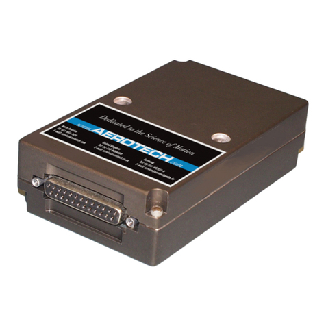
Aerotech Encoder Conditioning Unit User manual

Revision: 1.02.00
Encoder Conditioning Unit
(ECU)Hardware Manual

Global Technical Support
Go to www.aerotech.com/global-technical-support for information and support about your Aerotech, Inc. products. The
website supplies software, product manuals, Help files, training schedules, and PC-to-PC remote technical support. If
necessary, you can complete Product Return (RMA) forms and get information about repairs and spare or replacement parts.
To get help immediately, contact a service office or your sales representative. Include your customer order number in your
email or have it available before you call.
United States (World Headquarters)
Email: Support@aerotech.com
Phone: +1-412-967-6440
Fax: +1-412-967-6870
101 Zeta Drive
Pittsburgh, PA 15238-2811
www.aerotech.com
United Kingdom China
Email: Support@aerotech.com
Phone: +44 (0)1256 855055
Fax: +44 (0)1256 855649
Email: Support@aerotech.com
Phone: +86 (21) 5508 6731
Germany Taiwan
Email: Support@aerotech.com
Phone: +49 (0)911 967 9370
Fax: +49 (0)911 967 93720
Email: Support@aerotech.com
Phone: +886 (0)2 8751 6690
France
Email: Support@aerotech.com
Phone: +33 2 37 21 87 65
This manual contains proprietary information and may not be reproduced, disclosed, or used in whole or in part without the
express written permission of Aerotech, Inc. Product names mentioned herein are used for identification purposes only and
may be trademarks of their respective companies.
Copyright © 2012-2019, Aerotech, Inc., All rights reserved.

ECU Hardware Manual Declaration of Conformity
EU Declaration of Conformity
Manufacturer
Aerotech, Inc.
Address
101 Zeta Drive
Pittsburgh, PA 15238-2811
USA
Product
ECU
Model/Types
All
This is to certify that the aforementioned product is in accordance with the applicable requirements of the
following Directive(s):
2014/35/EU Low Voltage Directive
and has been designed to be in conformity with the applicable requirements of the following Standard(s)
when installed and used in accordance with the manufacturer’s supplied installation instructions.
BS EN 61000
BSEN 55011
Authorized Representative:
Simon Smith, European Director
Address:
Aerotech Ltd
The Old Brick Kiln, Ramsdell, Tadley
Hampshire RG26 5PR
UK
Name
/ Alex Weibel
Position
Engineer Verifying Compliance
Location
Pittsburgh, PA
Date
10/8/2019
www.aerotech.com 3

Declaration of Conformity ECU Hardware Manual
4 www.aerotech.com
This page intentionally left blank.

ECU Hardware Manual Encoder Conditioning Unit
Chapter 1: Encoder Conditioning Unit (ECU)
The ECUinterface is designed for use with any 1 Vpp analog encoder.
It dynamically applies Automatic Offset, Balance and Gain Control (AOC, ABC, AGC) to the input signals.
Accurate, constant amplitude 1 Vpp industry standard signals are then output.
A tri-colored LED indicates input signal strength and allows ease of setup for optimum performance. If this
LED is not visible when the interface is installed, a separate external setup signal can be used and a
calibration cycle also helps to simplify installation.
These features result in the output signals having very low cyclic error, typically less than 50 nm.
The interface is fully RoHS compliant and also supports readheads with single or dual limit outputs.
lCompatible with all standard 1 Vpp analog output readheads
lOutputs accurate, industry standard, 1 Vpp analog differential signals
lLow cyclic error
lTri-color integral setup LED
lUser selectable automatic gain control (AGC)
lAutomatic offset and balance control (AOC and ABC)
lSingle or dual-limit capability
www.aerotech.com 5

Encoder Conditioning Unit ECU Hardware Manual
1.1. Interface Features
1.1.1. Self-Tuning Active Correction
The ECU interface actively corrects for input signal imperfections to optimize system accuracy. Corrections
are made for the following:
Automatic Offset Control (AOC) adjusts offset independently for the sine and cosine signals
Automatic Gain Control (AGC) ensures consistent 1 Vpp signal amplitude
Automatic Balance Control (ABC) adjusts the gain to equalize the sine and cosine signals
These correction mechanisms operate over the full working speed range of the readhead. The user can
disable/enable the AGC by pressing the calibrate button for greater than 3 seconds.
1.1.2. LED Indicators
The tri-colored SETUP LED provides visual feedback of signal strength and error condition for setup and
diagnostic use. It flashes Off momentarily to indicate a reference mark, up to 100 mm/s only
Table 1-1: Setup LED
Color State Indication %
Purple FLASHING High Signal Alarm Condition >135%
ON High Signal >110% and <135%
Blue FLASHING Over Speed Alarm Condition
ON Optimum Signal >90% and <110%
Green ON Acceptable Signal >70% and <90%
Orange ON Low Signal >50% and <70%
Red ON Unacceptable Signal >20% and <50%
FLASHING Unacceptable Signal Alarm Condition <20%
The Yellow CAL/AGC LED indicates when the ECU is in a calibration routine and whether or not AGC is
active
Table 1-2: CAL/AGCLED
Color State Indication
Yellow
ON AGC active
OFF AGC inactive
SLOWFLASH calibration routine
FASTFLASH calibration failure
6 www.aerotech.com

ECU Hardware Manual Encoder Conditioning Unit
1.1.3. Calibration Procedure
The calibration procedure is required to optimize the gain, balance and offset of the analog input signals in
the ECU interface.These settings are then stored and recalled for initial use at startup.
To calibrate the system, the following sequence should be carried out:
lPrior to calibration, AGC should be off. To switch AGC on or off, the calibrate button should be
pressed for more than 3 seconds. When AGC is on, the CAL/AGC LED will be on and when AGC is
off, the CAL/AGC LED will be off.
lInstall the readhead and set up to obtain optimum (1 Vpp) signal amplitude
lEnter the calibration routine by pressing the CALIBRATE button momentarily. The calibration
routine is indicated by slow flashing of the CAL/AGC LED.
lTraverse the readhead slowly past the scale until the CAL/AGC LED stops flashing. The calibration
cycle is now complete.
If calibration fails, the CAL/AGC LED will flash quickly instead of switching off. If this happens the
CALIBRATE button should be pressed momentarily to exit the calibration routine. The calibration procedure
should then be repeated.
If the unit continues to fail calibration, factory default settings should be restored by powering down, then
pressing the CALIBRATE button as power is re-applied. The calibration procedure should then be repeated.
N O T E : To exit the calibration routine at any time, the CALIBRATE button should be pressed
momentarily.
www.aerotech.com 7

Encoder Conditioning Unit ECU Hardware Manual
1.2. Operating and Electrical Specifications
Table 1-3: Analog Specifications
Specification Description
Power
Supply
5 V -5% + 10%
ANALOG:150 mA current consumption (interface only), when
terminated with 120 Ω. Provision is given to feed a maximum of an
additional 100 mA to the readhead. The interface will be fully active <300
ms after power is applied. Encoder systems must be powered from a 5 V
dc supply complying with the requirements for SELV of standard EN
(IEC) 60950. Provision is given for remote sensing via two conductors of
the cable. The interface and readhead are protected from reverse voltage
and over voltage of up to 12 V.
Ripple 200 mVpp maximum @ frequency up to 500 kHz maximum
Acceleration Operating 500 m/s2BS EN60068-2-7:1993 (IEC 68-2-7:1983)
Shock Non-Operating 1000 m/s2, 6 ms, 1/2 sine BS EN60068-2-27:1993 (IEC 68-2-27:1987)
Vibration Operating 100 m/s2, 55 to 2000 Hz BS EN60068-2-6:1996 (IEC 68-2-6:1995)
Temperature Storage -20°C to +70°C
Operating 0°C to +55°C
Humidity Storage 95% maximum relative humidity (non-condensing)
Operating 80% maximum relative humidity (non-condensing)
Sealing IP40
Mass 95 g
EMCCompliance BS EN 61000 BS EN 55011
Connectors (input/output) 15-Pin D type socket/plug
8 www.aerotech.com

ECU Hardware Manual Encoder Conditioning Unit
1.3. I/O Signals
The ECU interface is designed to be used with industry standard 1 Vpp readheads. Cos, Sin, and reference
mark differential input signals should have nominal signal amplitude of 1 Vpp developed across 120 Ω input
termination resistor.
One or two open collector limit switch signals, active high or active low can also be input.
Table 1-4: 15 Pin ‘D’ Type Socket
Pin Signal Description Connector
1 COS-N Cosine-N
2 SIN-N Sine-N
3 MRK Reference mark
4 5 V 5 V power supply
5 5 V 5 V power supply
6 – Not connected
7 SETUP Setup signal/second (P) limit switch on dual limit readheads
8VqFirst (Q) limit switch
9 COS Cosine
10 SIN Sine
11 MRK-N Reference mark
12 COM 0 V power supply
13 COM 0 V power supply
14 – Do not connect
15 Inner Cable’s inner shield connection to 0 V
Table 1-5: 15 Pin ‘D’ Type Plug
Pin Signal Description Connector
1 COS-N Cosine-N
2 SIN-N Sine-N
3 MRK Reference mark
4 5 V 5 V power supply
5 5 V 5 V power supply
6 BID Bi/uni-directional reference mark select
7 SETUP Setup signal/P limit switch on dual limit readheads
8VqQ limit switch
9 COS Cosine
10 SIN Sine
11 MRK-N Reference mark
12 COM 0 V power supply
13 COM 0 V power supply
14 DIR Direction selector for reference mark
15 - Not connected
www.aerotech.com 9

Encoder Conditioning Unit ECU Hardware Manual
Figure 1-1: Analog Output Specifications
W A R N I N G : The outer shield should be connected to the earth ground. The inner shield
should be connected to 0V. Care should be taken to ensure that the inner and outer shields are
insulated from each other. If the inner and outer shields are connected together, this will cause a
short between 0V and earth, which could cause electrical noise issues.
10 www.aerotech.com

ECU Hardware Manual Encoder Conditioning Unit
1.4. Dimensions
Figure 1-2: ECU Dimensions
Figure 1-3: ECUStandard Interconnection Cable (C23191)
www.aerotech.com 11

Encoder Conditioning Unit ECU Hardware Manual
Figure 1-4: ECUCable for TLG (C23610)
Figure 1-5: ECUHi-Flex Cable for TLG (C23660)
12 www.aerotech.com

ECU Hardware Manual Warranty and Field Service
Appendix A: Warranty and Field Service
Aerotech, Inc. warrants its products to be free from harmful defects caused by faulty materials or poor
workmanship for a minimum period of one year from date of shipment from Aerotech. Aerotech’s liability is
limited to replacing, repairing or issuing credit, at its option, for any products that are returned by the original
purchaser during the warranty period. Aerotech makes no warranty that its products are fit for the use or
purpose to which they may be put by the buyer, whether or not such use or purpose has been disclosed to
Aerotech in specifications or drawings previously or subsequently provided, or whether or not Aerotech’s
products are specifically designed and/or manufactured for buyer’s use or purpose. Aerotech’s liability on
any claim for loss or damage arising out of the sale, resale, or use of any of its products shall in no event
exceed the selling price of the unit.
THE EXPRESS WARRANTY SET FORTH HEREIN IS IN LIEU OF AND EXCLUDES ALL OTHER
WARRANTIES, EXPRESSED OR IMPLIED, BY OPERATION OF LAW OR OTHERWISE. IN NO
EVENT SHALL AEROTECH BE LIABLE FOR CONSEQUENTIAL OR SPECIAL DAMAGES.
Return Products Procedure
Claims for shipment damage (evident or concealed) must be filed with the carrier by the buyer. Aerotech
must be notified within thirty (30) days of shipment of incorrect material. No product may be returned,
whether in warranty or out of warranty, without first obtaining approval from Aerotech. No credit will be given
nor repairs made for products returned without such approval. A "Return Materials Authorization (RMA)"
number must accompany any returned product(s). The RMA number may be obtained by calling an Aerotech
service center or by submitting the appropriate request available on our website (www.aerotech.com).
Products must be returned, prepaid, to an Aerotech service center (no C.O.D. or Collect Freight accepted).
The status of any product returned later than thirty (30) days after the issuance of a return authorization
number will be subject to review.
Visit https://www.aerotech.com/global-technical-support.aspx for the location of your nearest Aerotech
Service center.
Returned Product Warranty Determination
After Aerotech's examination, warranty or out-of-warranty status will be determined. If upon Aerotech's
examination a warranted defect exists, then the product(s) will be repaired at no charge and shipped,
prepaid, back to the buyer. If the buyer desires an expedited method of return, the product(s) will be shipped
collect. Warranty repairs do not extend the original warranty period.
Fixed Fee Repairs - Products having fixed-fee pricing will require a valid purchase order or credit card
particulars before any service work can begin.
All Other Repairs - After Aerotech's evaluation, the buyer shall be notified of the repair cost. At such
time the buyer must issue a valid purchase order to cover the cost of the repair and freight, or authorize
the product(s) to be shipped back as is, at the buyer's expense. Failure to obtain a purchase order
number or approval within thirty (30) days of notification will result in the product(s) being returned as is,
at the buyer's expense.
Repair work is warranted for ninety (90) days from date of shipment. Replacement components are
warranted for one year from date of shipment.
www.aerotech.com Appendix A 13

Warranty and Field Service ECU Hardware Manual
Rush Service
At times, the buyer may desire to expedite a repair. Regardless of warranty or out-of-warranty status, the
buyer must issue a valid purchase order to cover the added rush service cost. Rush service is subject to
Aerotech's approval.
On-site Warranty Repair
If an Aerotech product cannot be made functional by telephone assistance or by sending and having the
customer install replacement parts, and cannot be returned to the Aerotech service center for repair, and if
Aerotech determines the problem could be warranty-related, then the following policy applies:
Aerotech will provide an on-site Field Service Representative in a reasonable amount of time, provided
that the customer issues a valid purchase order to Aerotech covering all transportation and subsistence
costs. For warranty field repairs, the customer will not be charged for the cost of labor and material. If
service is rendered at times other than normal work periods, then special rates apply.
If during the on-site repair it is determined the problem is not warranty related, then the terms and
conditions stated in the following “On-Site Non-Warranty Repair” section apply.
On-site Non-Warranty Repair
If any Aerotech product cannot be made functional by telephone assistance or purchased replacement parts,
and cannot be returned to the Aerotech service center for repair, then the following field service policy
applies:
Aerotech will provide an on-site Field Service Representative in a reasonable amount of time, provided
that the customer issues a valid purchase order to Aerotech covering all transportation and subsistence
costs and the prevailing labor cost, including travel time, necessary to complete the repair.
Service Locations
http://www.aerotech.com/contact-sales.aspx?mapState=showMap
USA, CANADA, MEXICO CHINA GERMANY
Aerotech, Inc. Aerotech China Aerotech Germany
Global Headquarters Full-Service Subsidiary Full-Service Subsidiary
Phone: +1-412-967-6440 Phone: +86 (21) 5508 6731 Phone: +49 (0)911 967 9370
Fax: +1-412-967-6870 Fax: +49 (0)911 967 93720
TAIWAN UNITED KINGDOM
Aerotech Taiwan Aerotech United Kingdom
Full-Service Subsidiary Full-Service Subsidiary
Phone: +886 (0)2 8751 6690 Phone: +44 (0)1256 855055
Fax: +44 (0)1256 855649
Have your customer order number ready before calling.
14 Appendix A www.aerotech.com

ECU Hardware Manual Revision History
Appendix B: Revision History
Revision Description
1.02.00 Updated Cable Drawings
1.01.00 Updated Declaration of Conformity
1.00.00 New Manual
www.aerotech.com Appendix B 15

Revision History ECU Hardware Manual
16 Appendix B www.aerotech.com
This page intentionally left blank.

www.aerotech.com Index 17
Index
2
2014/35/EU 3
A
ABC 6
AGC 6
Analog Output Specifications 10
AOC 6
Automatic Balance Control (ABC) 6
Automatic Gain Control (AGC) 6
Automatic Offset Control (AOC) 6
C
Cable 11
CAL/AGC LED 6
Calibration 7
D
Declaration of Conformity 3
Dimensions 11
E
Electrical Specifications 8
G
Global Technical Support 2
L
LED Indicators 6
O
Operating and Electrical Specifications 8
R
Revision History 15
S
Self-Tuning Active Correction 6
Setup LED 6
Support 2
T
Technical Support 2
ECU Hardware Manual Index

Index ECU Hardware Manual
18 Index www.aerotech.com
This page intentionally left blank.
Table of contents
Other Aerotech Media Converter manuals
