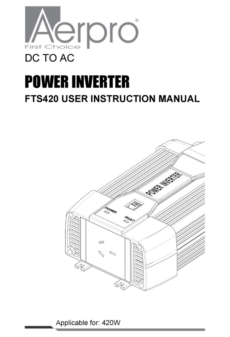
Aerpro API600W User manual

aerpro.com
For more information on the
Aerpro range go to our website
API600W
API800W
MODIFIED SINE WAVE INVERTER
12V DC TO 220V-240V AC 50Hz
USER MANUAL

2
Table of contents.............................................................2
Introduction......................................................................3
Features..........................................................................3
Specifications..................................................................4
Safety first........................................................................5
Safety features................................................................7
operating environment.....................................................7
operating instructions......................................................8
Power supply.................................................................10
Trouble shooting............................................................14
Technical assistance.....................................................15
1. TABLE OF CONTENTS

The Aerpro API600W/API800W is an easy to use power
inverter that is capable of providing 240V power from a
12V battery source. It allows you to power 240V
appliances from a 12V battery (i.e your vehicle battery)
and is ideal for use when a standard household 240V
power point is not accessible. With 600W/800W
continuous and 1200W/1600W peak power, this inverter is
suitable for many small devices. The API600W/API800W
is a Modified Sine Wave inverter, suitable for non-sensitive
appliances. It has all the safety features you need
including overload and short circuit protection, and
connects directly to a battery via the supplied 80cm lead
with alligator clips or ring terminals.
2. INTRODUCTION
•Modified sine wave, suitable for non-sensitive appliances
•1200W Peak power, 600W continuous power (API600W)
•1600W Peak power, 800W continuous power (API800W)
•Provides 240V power from a 12V battery source
•Operate small 240V non-sensitive devices
•Single 240VAC output socket for dedicated running of a
single appliance
•2.1A USB Port for charging/powering a USB device
•Over temperature & overload protection to prevent
damage to the battery, inverter or appliance
3. FEATURES
3

4
4. SPECIFICATIONS
600W
1200W
35A x2
Modified Sine Wave
12.8V-13.2V
230V±5%
11V-15V
DC 5V 2100mA
>80%
10.5V±0.5V
9.5V±0.5
15.5V±0.5V
Yes
≥720W ≥960W
Yes
-10°C to 40°C
80cm
800W
1600W
50A x2
Rated power
Peak power
Fuse (Internal)
Output waveform
Input voltage
Output voltage
Working voltage
USB output
Max output efficiency
Low voltage alarm
Low voltage shutdown (no load)
Over voltage shutdown (no load)
Overload alarm
Overload shutdown
Short circuit protection
Environment temperature
Cable length
API800WAPI600W

5
Incorrect installation or misuse of the inverter may result in
danger to the user or hazardous conditions. We urge you
to pay special attention to all CAUTION and WARNING
statements. CAUTION statements identify conditions or
practices that may result in damage to the inverter or to
other equipment.
WARNING statements identify conditions that may result
in personal injury or loss of life.
WARNING! Shock hazard! Keep away from children
The inverter generates the same potentially lethal AC
power as a normal household wall outlet. Treat it as you
use any other AC outlet.
- Do not insert foreign objects into the inverter’s AC outlet,
fan or vent openings.
- Do not expose the inverter to water, rain, snow or spray.
- Do not, under any circumstance, connect the inverter to
AC Power.
WARNING! Ventilation
The inverters housing may become uncomfortably warm,
reaching 140F (60℃) under extended high power
operation. Ensure at least 2 inches (5 cm) of air space is
maintained on all sides of the inverter for adequate
cooling. During operation, keep away from materials that
may be affected by high temperature.
5. SAFETY FIRST

6
WARNING! Explosion hazard
- Do not use the inverter in the presence of flammable
fumes or gases, such as in the bilge of a petrol powered
boat, or near propane tanks.
- Do not use the inverter in an enclosure containing
automotive-type, lead-acid batteries. These batteries,
unlike sealed batteries, vent explosive hydrogen gas which
can be ignited by sparks from electrical connection.
- When working on electrical equipment always ensure
someone is nearby to help you in an emergency.
CAUTION!
- Do not connect live AC power to the inverter’s AC
outlets. The inverter will be damaged even if it is switched
OFF.
- Do not expose the inverter to temperatures exceeding
104F(40℃).
CAUTION!
Do not use the inverter with the following equipment:
- Small battery operated products such as rechargeable
flashlights, some rechargeable shavers and night lights
that are plugged directly into an AC receptacle to
recharge.
- Certain battery chargers for battery packs used in hand
powered tools. These chargers will have warning labels
stating that dangerous voltages are present at the
charger’s battery terminals.
5. SAFETY FIRST

7
CAUTION!
Check that the battery voltage (12 Volt) is the same as the
input voltage of power inverter (for example, DC 12V of
battery connected with input voltage 12V of the inverter)
5. SAFETY FIRST
- Input protections: Polarity reverse(Fuse broken)/Over
and under voltage and shut Down
- Output protections: Short circuit/Overload/Over
temperature
- Power ON/OFF SWITCH and LED indicator
- Input and output full isolation
- Low standby power consumption.
6. SAFETY FEATURES
- For safe and optimum performance, install the inverter in
a location that is dry
- Do not expose to water or spray, do not use or store in a
damp environment.
- Cooling - Operate only in ambient temperatures
between 0℃ and 40℃. Keep away from surface heating
vents or other heat producing equipment.
- Location - Clean and free of dust and dirt. This is
especially important if the inverter is used in a working
environment.
7. OPERATING ENVIRONMENT

8
(1) ON/OFF power switch
This switch turns ON/OFF the inverter
(2) Overload (Fault) indicator
If the LED overload on, indicates that the inverter is in a
state of warning or protection, cease use.
(3) Power indicator
When lit, it indicates the inverter has been turned on and is
ready for use.
(4) USB outlet
Output DC 5V 2100mA power for charging only
(5) AC outlets
Output AC power
8. OPERATING INSTRUCTIONS
123
4 5

9
8. OPERATING INSTRUCTIONS
(6) 12 Volt positive (+) terminal, for connection to the
positve (+) of a 12V battery
(7) High speed cooling fan
The fans cool the internal circuits automatically, while the
inverter is in working
(8) 12 Volt negetive (--) terminal, for connection to the
negetive (--) of a 12V battery
6
8
7

10
The power supply source needs to guarantee at least 10.5
Volt to max.15.0 Volt DC and enough permanent output to
operate the unit.
NOTE: Connecting the DC power in the wrong way
(reverse polarity) will destroy the power inverter and
may damage the electrical equipment in use, please
follow the steps below in the correct sequence and
make sure to use the inverter in the correct way.
9.1. Connecting to the power supply
1. Unpack the power inverter and ensure that the switch is
at the OFF position.
2. Supplied are one red and one black ring terminal to
alligator clamp cable for the battery.
3. Screw tightly the red ring terminal end cable to the
inverter’s “+” and attach the red alligator clamp/ring
terminal end to the vehicles battery’s “+” terminal.
4. Screw tightly the black ring terminal end cable to the
inverter’s “--” and attach the black alligator clamp/ring
terminal end to the vehicles battery’s “--” terminal.
5. Turn on the inverter switch, green light should come on
6. If green light is on the inverter is ready for the desired
electrical appliance to be plugged into the AC output
socket of the inverter.
Caution: Inverter may only be operated with 12 Volt
batteries. It cannot be operated at 6 Volts and at 24
Volts the inverter will be damaged!
9. POWER SUPPLY

11
9.2. Connecting the load
The load connected needs to lie within the specifications
of the power inverter .
- Insert the plug into the socket of the power inverter.
- Press the “On” switch-the green LED lights up, the unit is
operational.
- The LED will turn off if the voltage drops below 10V and
the power inverter switches off-switch off the consumer
and disconnect the plug.
Caution: Never draw power from the power inverter
with an extension cable.
9.3. Rechargeable units
When a rechargeable unit is used for the first time,
observe the temperature for approx. 10 minutes, if it
becomes relatively hot, the unit cannot be operated using
the power inverter.
Rechargeable units can be easily operated using a
separate charger or transformer.
Caution: Some rechargeable units can be directly
connected to standard sockets. These units can
damage the power inverter.
9.4. Fuse
The power inverter is fitted with a barrel fuse in the cap of
the cigar lighter plug. Defective or blown fuses should be
exchanged with new fuses of the same rating by
unscrewing the cap of the cigarette lighter plug.
9. POWER SUPPLY

9. POWER SUPPLY
9.5. Position of the power
- No liquid may be allowed to enter the unit.
- The ambient temperature should lie between 10°and
27℃, do not place on or directly adjacent to a heat source.
- Do not expose to direct sunlight..
- Do not place any objects on top.
- Do not use close to inflammable materials or in a places
where inflammable vapors or smoke can occur.
9.6. Connection via the vehicle’s battery
It is recommended running the vehicle’s motor for
approx.15 minutes every hour to prevent the battery from
discharging. The power inverter can be operated when the
motor is running or when the motor is at a standstill.
It is possible that the power inverter may not work due to
the voltage drop during the starting process.
9.7. Alarm (low battery voltage)
The power inverter switches off automatically when the
voltage drops below 10 Volt.
9.8. Malfunctions (Protective features of the power
inverter)
Low battery voltage may damage the battery but not the
power inverter as it switches off. Once the normal
operating voltage is reinstated, the unit can be operated
again.
Overload protection - If the incoming voltage exceeds
15Volt DC, or if the permanent output is exceeded, the unit
switches off automatically.
12

9. POWER SUPPLY
Short-circuit protection - If the wires are crossed or the
output has short-circuited, this usually causes the 20 amp
fuse to blow. Unplug the load from the power inverter and
exchange the fuse.
Overheating protection - If the internal temperature of
65℃ is exceeded, the unit switches off automatically.
After a cool-down phase of approx.15 minutes, the unit
can be switched on again.
9.9. General Problems
Some inductive motors may require several start-up
attempts. If the device only runs for a moment, switch the
power inverter on and off quickly and repeat until the
device runs.
Humming in music systems
The loudspeakers of some stereo systems may hum as
they cannot filter the modified sine waves that the power
inverter generates.
Problems when operating a TV
The power inverter is already screened, although there
may be visible interference, especially if the TV signal is
weak. Try one of the following actions:
Position the power inverter as far away as possible from
the unit, the aerial and the aerial cable.
Look for the best possible position for the aerial cable, the
power cable, the TV and the power inverter, use good
quality aerial cables.
13

10. TROUBLESHOOTING
Problem: Low outgoing voltage
Solution: • The power inverter is overloaded Incoming
voltage is below 10.6 Volts.
• Reduce the outgoing output.
• Ensure adequate incoming voltage of over 10.6 volts
Problem: battery power is too low
Solution: • Poor condition of the battery Inadequate
power supply or inappropriate voltage drops
• Replace the battery
Problem: No output
Solution: • The power inverter is not at operating
temperature.
• Switch the power inverter off and on again.
• If necessary repeat the process until the operated unit
starts.
14

10. TECHNICAL ASSISTANCE
Never disassemble or repair the inverter by yourself.
If you need assistance setting up or have an issue
regarding the use of your Aerpro product contact Aerpro
Customer Support. Australian Agent:
TEL: 03 – 8587 8898 FAX: 03 – 8587 8866
Mon-Fri 9am – 5pm AEST
For more information, manuals, software or other products
in the Aerpro range please go to our website. Aerpro.com
This manual is considered correct at time of printing but is
subject to change.
For latest manuals and updates refer to the website.
Please retain this user guide for future reference.
15
This manual suits for next models
1
Table of contents
Other Aerpro Inverter manuals


