40-7170 Revision 1.5a August 10, 2009
5
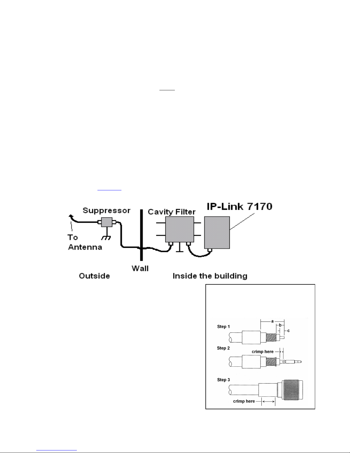
B. Bandpass Cavity Filter(s):
Heavy duty radio filter minimizes interferences from other RF Sources and maximizes
the range of the system. Dual System includes two EMR Corp. model 65610 Band Pass
cavity filters. Sizes vary according to radio frequency. Typical size of a 465 MHz
(UHF) filter is 17”h x 10”w x 10”d.
C. Antenna(s):
Rugged large antenna to maximize the range of the Base station IP-Link Transceiver.
Size and gain vary according the installation requirements and radio frequency. Typical
size for a UHF antenna is approximately 8 feet in height, with 9db gain.
See Section 5 for equipment and antenna separation note. The use of High Gain
Antennas is not approved for use in a UL installation or for NFPA 72 compliance.
D. Cables and connectors:
Low-Loss RG-8 (Belden 9913 type) coax cable is supplied with appropriate “N- Type”
connectors for maximum performance. For NFPA 72 compliance the RG8 Coax must be
physically protected in conduit between the antenna and the 7170’s enclosure.
E. Surge Suppressor(s):
A device installed in the coaxial transmission line to help protect components and
structure against surges like those produced by lightning. The device dissipates surges to
an earth ground that is connected to the device’s mounting bracket.
Use only AES part 52-0054.
F. Internal Modem:
IP-Link’s are equipped with an internal Modem for backup communication when TCP/IP
communication is delayed or unavailable. During the IP-Link’s initialization process the
modem is tested using both programmed phone numbers. During those tests the Modem
LED will be on and the Console Port unavailable. If either number fails to connect to an
assigned MultiNet Receiver, it will be re-tested randomly every 5 to 10 minutes until it
passes or the maximum number of 5 attempts is reached.
If during normal operation TCP/IP heartbeat fails, the IP-Link’s RF goes offline
transmitting a “Receiver Not in Service” message. That message will notify other
IntelliNet devices to select a secondary IP-Link for communicating. The modem is again
tested, and if it passes any stored messages are passed to the MultiNet receiver and RF
goes back online by transmitting a “Receiver Ready” message. Until the TCP/IP
connection returns satisfactorily, communication to the MultiNet receiver will occur
using the modem. Sending of Alarm messages via modem are attempted immediately
after reception. All other less significant messages may be discarded.
The modem, using both phone numbers is tested daily. Interval between daily test
attempts is 24 hours plus a random number of minutes up to 30, after the preceding tests
pass. This means that the time of day that the daily modem tests occur, randomly
advance. This helps to spread out multiple IP-Link testing.
G. Typical Unique Installation Tool Requirements:
The primary tools required to install an IP-Link Transceiver are as follows.
Power or SWR Meter Large Wire Cutters Weatherproof Tape
Coax Connector Crimping Tool RG-8U Coax Strippers
Serial Terminal or PC running a terminal program Silicon Sealant