Aewin AW-BS611 User manual

SOM-ETX CPU Board
Model Number AW-BS611
Intel Ultra Low Power Pentium® III Processor with VGA/LCD/LVDS,
LAN, TV-out & Audio
User’s Manual
Version 1.0
We embed your need! ©Copyright 2002

User’s Manual
© Copyright 2002. All Rights Reserved
Manual Edition 1.0, February 2005
This document contains proprietary information protected by copyright. All rights are
reserved, no part of this manual may be reproduced, copied, translated or transmitted in
any form or by any means without prior written permission of the manufacturer.
The content of this manual is intended to be accurate and reliable, the original
manufacturer assumes no responsibility for any inaccuracies that may be contained in this
manual. The original manufacturer reserves the right to make improvements to the
products described in this manual at any time without prior notice.
Trademarks
IBM, EGA, VGA, XT/AT, OS/2 and PS/2 are registered trademarks of International business
Machine Corporation
Award is a trademark of Award Software International, Inc
Intel is a trademark of Intel
RTL is a trademark of Realtek
VIA is a trademark of VIA Technologies, Inc
Microsoft, Windows, Windows NT and MS-DOS are either trademarks or registered
trademarks of Microsoft Corporation
All other product names mentioned herein are used for identification purpose only and may
be trademarks and/or registered trademarks of their respective companies
Limitation of Liability
While reasonable efforts have been made to ensure the accuracy of this manual, the
manufacturer and distributor assume no liability resulting from errors or omissions in this
manual, or from the use of the information contained herein.
©2002 AEWIN Technologies Co., Ltd. All rights reserved. 2Ver 1.0. Feb. 2005

User’s Manual
Table of Contents
HTChapter 1. General Information-------------------------------------------------------------4TH
HT1.1 Introduction-----------------------------------------------------------------------------------4TH
HT1.2 Specification----------------------------------------------------------------------------------TH4
HT1.3 AW-BS611Package--------------------------------------------------------------------------6TH
HT1.4 Board Layout---------------------------------------------------------------------------------7TH
HT1.5 Board Dimension----------------------------------------------------------------------------7TH
HTChapter 2. Installing Process----------------------------------------------------------------TH-8
2HT.1 Installing Memory----------------------------------------------------------------------------8TH
HTChapter 3. BIOS Setup--------------------------------------------------------------------------TH11
3HT.1 Quick Setup------------------------------------------------------------------------------------11TH
3HT.2 Entering the CMOS Setup Program----------------------------------------------------12TH
3HT.3 Menu Options----------------------------------------------------------------------------------TH13
HTStandard CMOS Features-----------------------------------------------------------------------14TH
HTAdvanced BIOS Features-----------------------------------------------------------------------16TH
HTAdvanced Chipset Features-------------------------------------------------------------------19TH
HTIntegrated Peripherals---------------------------------------------------------------------------22TH
HTPower Management Setup----------------------------------------------------------------------23TH
HTPNP/PCI Configuration---------------------------------------------------------------------------25TH
HTPC Health Status-----------------------------------------------------------------------------------27TH
HTLoad Fail-Safe Default----------------------------------------------------------------------------28TH
HTLoad Optimized Default--------------------------------------------------------------------------29TH
HTSet Supervisor & User Password-------------------------------------------------------------30TH
HTChapter 4. Drivers Utility-------------------------------------------------------------------------32TH
4HT.1 System Driver Installation -----------------------------------------------------------------32TH
4HT.2 VGA Driver Installation----------------------------------------------------------------------35TH
HTAppendix A. THHTOptional Cable List--------------------------------------------------------------43TH
©2002 AEWIN Technologies Co., Ltd. All rights reserved. 3Ver 1.0. Feb. 2005

User’s Manual
Chapter 1. General Information
1.1Introduction
The AW-BS611 is an Intel® Low Voltage Intel® Pentium® III/Celeron processor
System On Module (SOM). Using an Intel® Pentium® III/Celeron® processor, the
AW-BS611 achieves quite good performance on the SOM-ETX CPU module.
On-board features include two TTL (16550 compatible) serial ports, one bi-directional
parallel (ECP/EPP/SPP) port, four USB ports, one FPC type floppy disk connector, SIR
IrDA 1.1 compliant and a keyboard/PS2 mouse interface. The two IDE devices
supports Ultra DMA 33/66/100 mode with data transfer rate up to 100MB/sec. In
addition, the board’s watchdog timer can automatically reset the system or generate an
interrupt if the system stops due to a program bug or EMI. The built-in VIABT82C686B
supports temperatures, fan speed and voltages monitoring function. The small size
(94mm x 114mm) and use of four high capacity connector based on the proven
SOM-ETX form factor, allow the SOM-ETX modules to be easily and securely mounted
onto a customized solution board or our standard AW-BP100 5.25” SOM-ETX base
board.
The AW-BS611 is a highly integrated multimedia SOM that combines audio,
video and network functions. It provides CRT/24-bit TTL TFT LCD and LVDS interface,
integrated AGP 4X 2D/3D graphic accelerator with system memory 8/16/32MB. Major
on-board devices adopt four ISA& PCI expansion interface to achieve good computing
performance when used with Intel® Pentium® III/Celeron® processor. The AW-BS611
also support TV-Out that supports NTSC/PAL format and audio controller based on
Realtek® ALC650 AC97 codec for multimedia applications.
1.2Specification
General Functions
CPU Intel®Ultra Low Power Pentium®III or Celeron®Processor
BIOS Award® 512KB Flash BIOS
Chipset VIA VT8606 + VT82C686B
©2002 AEWIN Technologies Co., Ltd. All rights reserved. 4Ver 1.0. Feb. 2005

User’s Manual
I/O Chipset VT82C686B built-in
Memory Onboard one 144-pin SO-DIMM socket supports up to 512MB SDRAM
Enhanced IDE Supports up to two IDE devices (Ultra DMA33/66/100)
FDD interface Support one FPC type floppy disk connector
Parallel port One bi-directional parallel ports and can be reconfigure to FDD interface;
supports SPP/ECP/EPP modes
Serial port Two TTL (16550 compatible) serial ports
IR interface Supports SIR IrDA1.1 compliant
KB/Mouse connector Support PS/2 keyboard/mouse
USB connectors Support four USB ports
Watchdog Timer Can generate a system reset, supports software selectable timeout interval
System Monitoring Built in VIA VT82C686B supports temp, fan speed and voltages monitoring
Expansion interface Supports ISA& PCI expansion interface
Flat Panel/CRT Interface
Chipset VIA Twister-T chip with integrated Savage4 2D/3D/VideoAccelerator
Display memory Share system memory 8/16/32MB
Interface 4X AGP VGA/LCD interface, support for 9,12,15,18,24 bit TFT and optional
16- or 24-bit DSTN panel
Display type Support CRT, 24bit TTL TFT LCD and LVDS interface
Output connector TTL TFT LCD connector on board, CRT & LVDS on base board
Ethernet Interface
Chipset Intel® 82551ER 100BASE-Tx Fast Ethernet controller
Output connector RJ-45 connector x 1 on the base board
TV-out Interface
Chipset VIA1621 digital TV encoder
TV format Supports NTSC and PAL signals format
Output connector Provides RCA (Composite) video and S-video connector on base board
Audio Interface
©2002 AEWIN Technologies Co., Ltd. All rights reserved. 5Ver 1.0. Feb. 2005

User’s Manual
Chipset Realtek® ALC650 AC97 codec
Output connector Audio connectors on base board
Form factor ETX form factor
Mechanical and Environmental
Power supply voltage VCC (4.75V to 5.25V)
Max. Power
Requirement 5A @5V
Operating
temperature 32 to 140 (0 to 60 )℉℃
Board size 4.5"(L) x 3.7"(W) (114mm x 94mm)
1.3 Package
Please make sure that the following materials have been packed with the board before
starting install your AW-BS611.
1. AW-BS610 SOM-ETX Board
2. Quick Setup Manual
3. Cable List:
46-ICOM00-00 2.54mm COM Port Cable
46-IUSB08-002.54mm USB Cable
Optional Cable
46-ATA660-00 IDE Cable
4. CD-ROM for Drivers, Utilities
If any of these parts are missing or damaged, please contact your distributor or sales
representatives immediately.
Note: for detailed contents of the AW-BS611, please refer to the attached CD-ROM.
©2002 AEWIN Technologies Co., Ltd. All rights reserved. 6Ver 1.0. Feb. 2005

User’s Manual
1.4 Board Layout
1.5Board Dimension
©2002 AEWIN Technologies Co., Ltd. All rights reserved. 7Ver 1.0. Feb. 2005
User’s Manual
Chapter 2. Installing Process
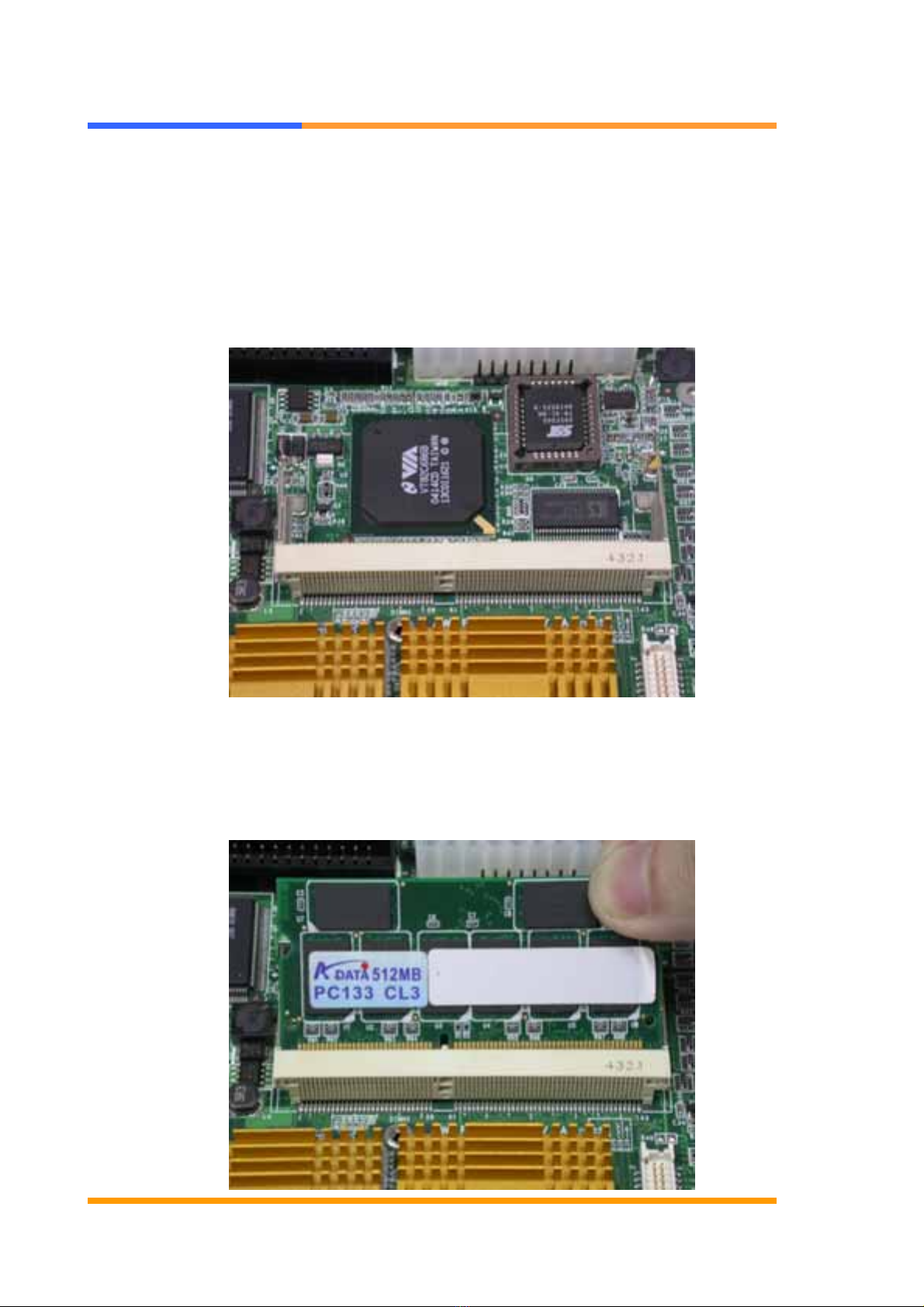
2.1 Installing Memory:
To insert a SDRAM Memory: The AW-BS610 onboard with one 144-pin DDR DIMM sockets
supports up to 512Mbytes DDR SDRAM.
To Insert a DIMM Memory: Please align the module with the socket key and press down until the
levers at each end of the socket snap close up.
There are two directions for installing a module in the socket. Do not attempt to force the module
into the socket incorrectly.
©2002 AEWIN Technologies Co., Ltd. All rights reserved. 8Ver 1.0. Feb. 2005

User’s Manual
©2002 AEWIN Technologies Co., Ltd. All rights reserved. 9Ver 1.0. Feb. 2005

User’s Manual
To Remove a DIMM Memory: To remove a DIMM, press down on the levers at both end of the
module until the module pops out
There is only one direction for installing a module in the socket. Do not attempt to force the
module into the socket incorrectly.
©2002 AEWIN Technologies Co., Ltd. All rights reserved. 10 Ver 1.0. Feb. 2005

User’s Manual
©2002 AEWIN Technologies Co., Ltd. All rights reserved. 11 Ver 1.0. Feb. 2005
Chapter 3. BIOS Setup
The ROM chip of your AW-A695 board is configured with a customized Basic Input/Output
System (BIOS) from Phoenix-Award BIOS. The BIOS is a set of permanently recorded
program routines that give the system its fundamental operational characteristics. It also
tests the computer and determines how the computer reacts to instructions that are part of
programs.
The BIOS is made up of code and programs that provide the device-level control for the
major I/O devices in the system. It contains a set of routines (called POST, for Power-On
Self Test) that check out the system when you turn it on. The BIOS also includes CMOS
Setup program, so no disk-based setup program is required CMOS RAM stores information
for:
Date and time
Memory capacity of the main board
Type of display adapter installed
Number and type of disk drives
The CMOS memory is maintained by battery installed on the AW-A695 board. By using
the battery, all memory in CMOS can be retained when the system power switch is turned
off. The system BIOS also supports easy way to reload the CMOS data when you replace
the battery of the battery power lose.
3.1 Quick Setup
In most cases, you can quickly configure the system by choosing the following main menu
options:
1. Choose “Load Optimized Defaults” from the main menu. This loads the setup default
values from the BIOS Features Setup and Chipset Features Setup screens.
2. Choose “Standard COS Features” from the main menu. This option lets you configure
the date and time, hard disk type, floppy disk drive type, primary display and more.
3. In the main menu, press F10 (“Save & Exit Setup”) to save your changes and reboot the
system.

User’s Manual
3.2Entering the CMOS Setup Program
Use the CMOS Setup program to modify the system parameters to reflect the options
installed in your system and to customized your system. For example, you should run the
Setup program after you:
Received an error code at startup
Install another disk drive
Use your system after not having used it for a long time
Find the original setup missing
Replace the battery
Change to a different type of CPU
Run the Phoenix-Award Flash program to update the system BIOS
Run the CMOS Setup program after you turn on the system. On-screen instructions
explain how to use the program.
Enter the CMOS Setup program’s main menu as follows:
1. Turn on or reboot the system. After the BIOS performs a series of diagnostic
checks, the following message appears:
“Press DEL to enter SETUP”
2. Press the <DEL> key to enter CMOS Setup program. The main menu appears:
©2002 AEWIN Technologies Co., Ltd. All rights reserved. 12 Ver 1.0. Feb. 2005

User’s Manual
©2002 AEWIN Technologies Co., Ltd. All rights reserved. 13 Ver 1.0. Feb. 2005
3. Choose a setup option with the arrow keys and press <Enter>. See the following
sections for a brief description of each setup option.
In the main menu, press F10 (“Save & Exit Setup) to save your changes and reboot the
system. Choosing “EXIT WITHOUT SAVING” ignores your changes and exits the
program. Pressing <ESC> anywhere in the program returns you to the main menu.
3.3 Menu Options
The main menu options of the CMOS Setup program are described in the following and the
following sections of this chapter.
STANDARD CMOS FEATURES:
Configure the date & time, hard disk drive type, floppy disk drive type, primary display type
and more
ADVANCED BIOS FEATURES:
Configure advanced system options such as enabling/disabling cache memory and shadow
RAM
ADVANCED CHIPSET FEATURES:
Configure advanced chipset register options such DRAM timing
INTEGRATED PERIPHERALS:
Configure onboard I/O functions
POWER MANAGEMENT SETUP:
Configure power management features such as timer selects
PNP/PCI CONFIGURATION:
Configure Plug & Play IRQ assignments and PCI slots
PC HEALTH STATUS:
Configure the CPU speed and, if the optional Winbond W83627HF system monitor IC is
installed, view system information

User’s Manual
FREQUENCY/VOLTAGE CONTROL
Use this menu to specify your settings for frequency/voltage control
LOAD FAIL-SAFE DEFAULT:
Loads BIOS default values. Use this option as diagnostic aid if your system behaves
erratically
LOAD OPTIMIZED DEFAULTS:
Use this menu to load the BIOS default values that are factory settings for optimal
performance system operations.
SET SUPERVISORS & USER PASSWORD:
Configure the system so that a password is required when the system boots or you attempt
to enter the CMOS setup program. When you log in with this password, you will be able to
enter the COS Setup main menu, but you can not enter other menus in the CMOS Setup
program.
SAVE & EXIT SETUP:
Save changes of values to CMOS and exit the CMOS setup program
EXIT WITHOUT SAVING:
Abandon all CMOS changes and exit the CMOS setup program
Standard CMOS Features Setup
Use the Standard CMOS Setup option as follows:
1. Choose “Standard CMOS Features” from the main menu. The following screen
appears:
©2002 AEWIN Technologies Co., Ltd. All rights reserved. 14 Ver 1.0. Feb. 2005

User’s Manual
2. Use the arrow keys to move between fields. Modify the selected field using the
PgUP/PgDN/+/- keys. Some fields let you enter numeric values directly.
Date and Time Configuration:
Type the current date
Hard Disks:
Choose from “Auto”, “User” or “None”
If your drive is not one of the predefined types, choose “User” and enter the following drive
specifications: Cylinders, heads, Wpcom, L-Zone, sectors and mode.
Consult the documentation received with the drive for the values that will give you optimum
performance.
Drive A & B:
Select the correct specifications for the floppy disk drive installed in the computer.
None: No floppy disk drive installed
360K/1.2M 5.25" standard drive
720K/1.44M/2.88M 3.5" standard drive
Video:
Choose: EGA/VGA
CGA 40 Color Graphics adapter, power up in 40 columns mode
CGA 80 Color Graphics adapter, power up in 80 columns mode
©2002 AEWIN Technologies Co., Ltd. All rights reserved. 15 Ver 1.0. Feb. 2005
Mono Monochrome adapter, includes high resolution monochrome adapters

User’s Manual
Halt On:
Controls whether the system stops in case of an error detected during power up.
Choose: All Errors (Default)
NoErrors
All, But Keyboard
All,ButDiskette
All,ButDisk/Key
3. After you have finished with the Standard CMOS Features program, press the <ESC>
key to return to the main menu.
4.
Advanced BIOS Features Setup
Use the Advanced BIOS Features Setup option as follows:
1. Choose “Advanced BIOS Features Setup” from the main menu. The following screen
appears:
©2002 AEWIN Technologies Co., Ltd. All rights reserved. 16 Ver 1.0. Feb. 2005
2. Use the arrow keys to move between items and to select values. Modify the selected
fields using the PgUP/PgDN keys. Press the <F1> “Help” key for information on the
available options:

User’s Manual
©2002 AEWIN Technologies Co., Ltd. All rights reserved. 17 Ver 1.0. Feb. 2005
Virus Warning:
When enabled, any attempt to write to the boot sector and partition table will halt the
system and cause a warning message to appear. If this happens, you can use an
anti-virus utility on a virus-free, bootable floppy disk to reboot and clean your system. The
default setting is disabled.
CPU Internal/External Cache:
The Cache memory is additional memory that is much faster than conventional system
memory. Most of modern PCs have additional external cache memory. When the CPU
requests data, the system transfers the requested data from the main DRAM into cache
memory. The external cache field may not appear if your system doesn’t have external
cache memory.
Choose: Enabled, Disabled
CPU L2 Cache ECC Checking:
When you select Enabled, memory checking is enable when the external cache contains
ECC SRAM.
Quick Power On Self Test:
Select Enabled to reduce the amount of time required to run the power-on-self-test (POST).
A quick POST skips certain steps. The manufacturer recommends that you normally
disable quick POST.
Choose: Enabled, Disabled
First/Second/Third Boot Device:
The BIOS attempts to load the operating system from the devices in the sequence selected
for these items.
Choose: Floppy, LS-120, HDH-0, 1, 2, 3, SCSI, CDROM, ZIP100, USB-FDD, USB-ZIP,
USB-CDROM, USB-HDD, LAN, Disabled
Boot Other Device:
If your boot device is not included the following devices Floppy, LS120, HDD0/1, SCSI,
CDROM, you may set First/Second/Third boot devices to disable and enable the boot other
device function, the system will automatically boot the other device.
Choose: Enabled, Disabled

User’s Manual
©2002 AEWIN Technologies Co., Ltd. All rights reserved. 18 Ver 1.0. Feb. 2005
Boot Up NumLock Status:
Choose On or Off. On puts the numeric keypad in Num Lock mode at boot-up. Off puts
the numeric keypad in arrow key mode at boo-up
Security Option:
Choose Setup or System. This lets you specify whether a password is required every time
the system boots or only when an attempt is made to enter the CMOS Setup program.
“Setup” – The password prompt only appears if you attempt to enter the CMOS setup
program.
“System” – The password prompt appears each time the system is booted.
Note: The password function is disabled by default. For a description of enabling
the password function, refer to the section: Supervisor Password & User Password
later in this chapter.
Baud Rate:
The data transfer rate (bit per second) to agent. Choose 9600/19200/38400/57600/115200
item.
Agent Wait Time (Min):
Agent negotiate time, choose 1/2/4/8 min.
Agent After Boot:
Choose enabled to enable agent administrate this board after boot.
Console Redirection:
Set the Console Redirection <Enabled>
This function is let you to connect the Server by hyper terminal to monitor Client, it has to be
worked under DOS mode. The Client terminal doesn’t need the graphic function.

User’s Manual
Advanced Chipset Features Setup
Use the Advanced Chipset Features Setup option as follows:
1. Choose “Advanced Chipset Features Setup” from the main menu. The following
screen appears:
2. Move between items and select values by using the arrow keys. Modify the selected
fields using the PnUP/PgDN keys. For information on the various options, press <F1>
key.
DRAM Timing By SPD:
It lets you select the value in this field, depending on the board paged DRAMs or EDO
(Extended Data Output) DRAMS.
Choose: Enabled / Disabled
DRAM Clock:
It lets you control the DRAM speed.
Choose: Host Clock, HCLK-33M, HCLK+33M
©2002 AEWIN Technologies Co., Ltd. All rights reserved. 19 Ver 1.0. Feb. 2005

User’s Manual
©2002 AEWIN Technologies Co., Ltd. All rights reserved. 20 Ver 1.0. Feb. 2005
SDRAM Cycle Length:
It sets the CAS latency timing.
Choose: 3 / 2
Bank Interleave:
Choose: 2 Bank / 4 Bank / Disabled
Memory Hole:
Choose Enabled or Disabled. You can reserve this area of system memory for ISA
adapter ROM. When this area is reserved, it cannot be cached. The user information of
peripherals that need to use this area of system memory usually discusses their memory
requirement.
System BIOS Cacheable:
Choose Enabled or Disabled. When enabled, caching of the system BIOS at
F0000h-FFFFFh, enhancing system performance. However, if any program writes to this
memory area, a system error may result.
Video RAM Cacheable:
Choose: Enabled / Disabled
Frame Buffer Size:
Choose: 2M / 4M / 8M / 16M / 32M
AGP Aperture Size:
Enter a value from 4MB to 128MB to determine the effective size of the graphics aperture
sued in the particular PAC configuration. The larger the value, the better the AGP
performance.
OnChip USB:
You could enable this function if the system contains USB (Universal Serial Bus) controller
and USB keyboard. When disabled, the system will not be able to access USB keyboard.
Choose: Enabled / Disabled
USB Keyboard/Mouse Support:
You could enable this function if the system contains USB controller and USB
keyboard/mouse
Choose: Enabled / Disabled
Table of contents
Other Aewin Computer Hardware manuals


Popular Computer Hardware manuals by other brands

NXP Semiconductors
NXP Semiconductors MCIMX93-EVK user manual

Verizon Wireless
Verizon Wireless AIRCARD 595 PC CARD user manual

Faroudja
Faroudja VP301 Installation & operation instructions

Synology
Synology NAS RS822+ Hardware installation guide

RTimes
RTimes X509 product manual

Vitek
Vitek VTQ-B04 operating instructions


