Aewin SCB-6971 User manual

User’s Manual
AEWIN Technologies Co., Ltd Aug, 2006
1
Network Appliance
Model Number SCB-6971
Desktop AMD®Geode®LX800 Network Appliance with four
LAN or three LAN and four switch, Mini PCI
User’s Manual
Version 1.0

User’s Manual
AEWIN Technologies Co., Ltd Aug, 2006
2
© Copyright 2006. All Rights Reserved
User’s Manual Edition 1.0,Aug 2006
This document contains proprietary information protected by copyright. All rights are reserved; no
part of this manual may be reproduced, copied, translated or transmitted in any form or by any means
without prior written permission of the manufacturer.
The content of this document is intended to be accurate and reliable; the original manufacturer assumes
no responsibility for any inaccuracies that may be contained in this manual. The original
manufacturer reserves the right to make improvements to the products described in this manual at any
time without prior notice.
Trademarks
IBM, EGA, VGA, XT/AT, OS/2 and PS/2 are registered trademarks of International business Machine
Corporation
Award is a trademark ofAward Software International, Inc
Intel is a trademark of Intel
RTL is a trademark of Realtek
VIA is a trademark of VIA Technologies, Inc
Microsoft, Windows, Windows NT and MS-DOS are either trademarks or registered trademarks of
Microsoft Corporation
All other product names mentioned herein are used for identification purpose only and may be
trademarks and/or registered trademarks of their respective companies
Limitation of Liability
While reasonable efforts have been made to ensure the accuracy of this document, the manufacturer
and distributor assume no liability resulting from errors or omissions in this document, or from the use
of the information contained herein.
For more information on SCB-6971 or other AEWIN products, please visit our website
http://www.aewin.com.tw.
For technical supports or free catalog, please send your inquiry to

User’s Manual
AEWIN Technologies Co., Ltd Aug, 2006
3
Table of Contents
Chapter 1. General Information.................................................................................4
1.1 Introducing.........................................................................................................4
1.2 Specification ......................................................................................................4
1.3 Order Information..............................................................................................5
1.4 Packaging...........................................................................................................5
1.5 Precautions.........................................................................................................5
1.6 System Layout ...................................................................................................7
1.7 Board Dimension...............................................................................................8
Chapter 2. Connector/Jumper Configuration.........................................................10
2.1 Connector/Jumper Location and Definition.....................................................10
2.2 Connector and Jumper Setting.........................................................................11
Chapter 3 BIOS Setup...............................................................................................17
3.1 Quick Setup......................................................................................................17
3.2 Entering the CMOS Setup Program.................................................................18
3.3 Menu Options...................................................................................................19
3.4 Standard CMOS Features Setup ......................................................................20
3.5 Advanced BIOS Features Setup.......................................................................21
3.6 Advanced Chipset Features Setup....................................................................23
3.7 Integrated Peripherals ......................................................................................23
3.8 PNP/PCI Configuration ...................................................................................25
3.9 PC Health Status Configuration Setup.............................................................26
3.10 Load Optimized Defaults...............................................................................27
3.11 Set User Password..........................................................................................27
3.12 Save and Exit Setup.......................................................................................28
3.13 Exit Without Saving.......................................................................................29
Chapter 4. Utility & Driver Installation...............................................................30
4.1 Operation System Supporting..........................................................................30
4.2 System Driver Installation ...............................................................................30
4.3 VGADriver Installation...................................................................................30
4.4 LAN Driver Installation...................................................................................31
Appendix A: Optional Accessory and Cable List....................................................33

User’s Manual
AEWIN Technologies Co., Ltd Aug, 2006
4
Chapter 1. General Information
1.1 Introducing
The SCB-6971 series is a low cost, low power network appliance. There are
two combinations. One is equipped with four 10/100Mbps LAN ports, the
other is with three 10/100 LAN and four 10/100 switch. Also, the system is
equipped with one RJ45 console port.
It is designed to be a desktop form factor with 10 LED indicators for LAN,
power and storage. Besides, SCB-6971 can support one Mini PCI for
expansion use, one CcompactFlash Type I/II socket for OS installation.
The SCB-6971 series is positioned in SMB/SOHO segment, suitable for
Firewall, VPN, Load Balancing, IPS, IDS application, etc.
1.2 Specification
General Functions
CPU AMD® Geode® LX800
Chipset AMD® Geode® CS5536
Memory One DDR DIMM socket support up to 1GB
Ethernet Four 10/100Mbps PCI bus Ethernet ports utilizing four Realtek®
8139CL+ Ethernet controllers or three 10/100Mbps & four 10/100 switch
I/O Port One RJ45 console port
Expansion Slot One Mini PCI socket
SSD One 50-pin CompactFlashTM type I/II socket
Mechanical and Environmental
LCD Indicator 10 LED indicators for Power/HDD/LAN active & speed
Power Supply 30W +5V DC IN power adapter
OperatingTemperature 32 to 104°F (0 to 40°C)
Storage Temperature -4 to 167°F (-20 to 75°C)
Humidity 5 to 95% relative humidity, non-operating, non-condensing
Dimension(W x D x H)225mm (W) x 152mm (D) x 30mm (H) (8.9” W x 6.0” D x 1.2” H)
Certification CE/FCC
* Note: All specifications are subject to change without prior notice

User’s Manual
AEWIN Technologies Co., Ltd Aug, 2006
5
1.3 Order Information
We offer various combination of SCB-6971 control board according to LAN
difference, it is to meet various need in the market.
Model Description
SCB-6971A-050-A Desktop AMD Geode LX800 Network Appliance with Four 10/100 LAN,
Mini PCI
SCB-6971B-050-B Desktop AMD Geode LX800 Network Appliance with Three 10/100 LAN
and Four 10/100 switch, Mini PCI
MB06018-1-01 Adapter Module of VGA header
46-I0002X6-00 2mm, 20cm cable of MB06018
1.4 Packaging
Please make sure that the following items have been included in the package
before installation.
1. SCB-6971 chassis *1
2. SCB-6971 main board * 1
3. Cables (Optional)
1. CD-ROM that contains the following folders:
(1) Manual
(2) System Driver
(3) Ethernet Driver
(4) Utility Tools
If any item of above is missing or damaged, please contact your dealer or
retailer from whom you purchased the SCB-6971. Keep the box and carton
when you probably ship or store SCB-6971 in near future. After you unpack the
goods, inspect and make sure the packaging is intact. Do not plug the power
adapter to the main board of SCB-6971 if you already find it appears damaged.
Note: Keep the SCB-6971 in the original packaging until you start
installation.
1.5 Precautions
Please make sure you properly ground yourself before handling the SCB-6971
control board or other system components. Electrostatic discharge can be
easily damage the SCB-6971 control board.

User’s Manual
AEWIN Technologies Co., Ltd Aug, 2006
6
Do not remove the anti-static packing until you are ready to install the
SCB-6971 control board.
Ground yourself before removing any system component from it protective
anti-static packaging. To ground yourself, grasp the expansion slot covers or
other unpainted parts of the computer chassis.
Handle the SCB-6971 control board by its edges and avoid touching the
components on it.

User’s Manual
AEWIN Technologies Co., Ltd Aug, 2006
7
1.6 System Layout
SCB-6971A-050-A:
SCB-6971B-050-B:
(Front Side)
(Rear Side)
(Front Side)
(Rear Side)

User’s Manual
AEWIN Technologies Co., Ltd Aug, 2006
8
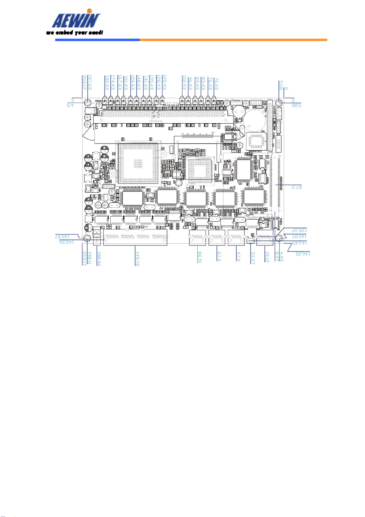
Board Layout: (SCB-6971B-050-B)
1.7 Board Dimension
SCB-6971A-050-A
Main board
User’s Manual
AEWIN Technologies Co., Ltd Aug, 2006
9
SCB-6971B-050-B
Main board

User’s Manual
AEWIN Technologies Co., Ltd Aug, 2006
10
Chapter 2. Connector/Jumper Configuration
2.1 Connector/Jumper Location and Definition
User’s Manual
AEWIN Technologies Co., Ltd Aug, 2006
11
2.2 Connector and Jumper Setting
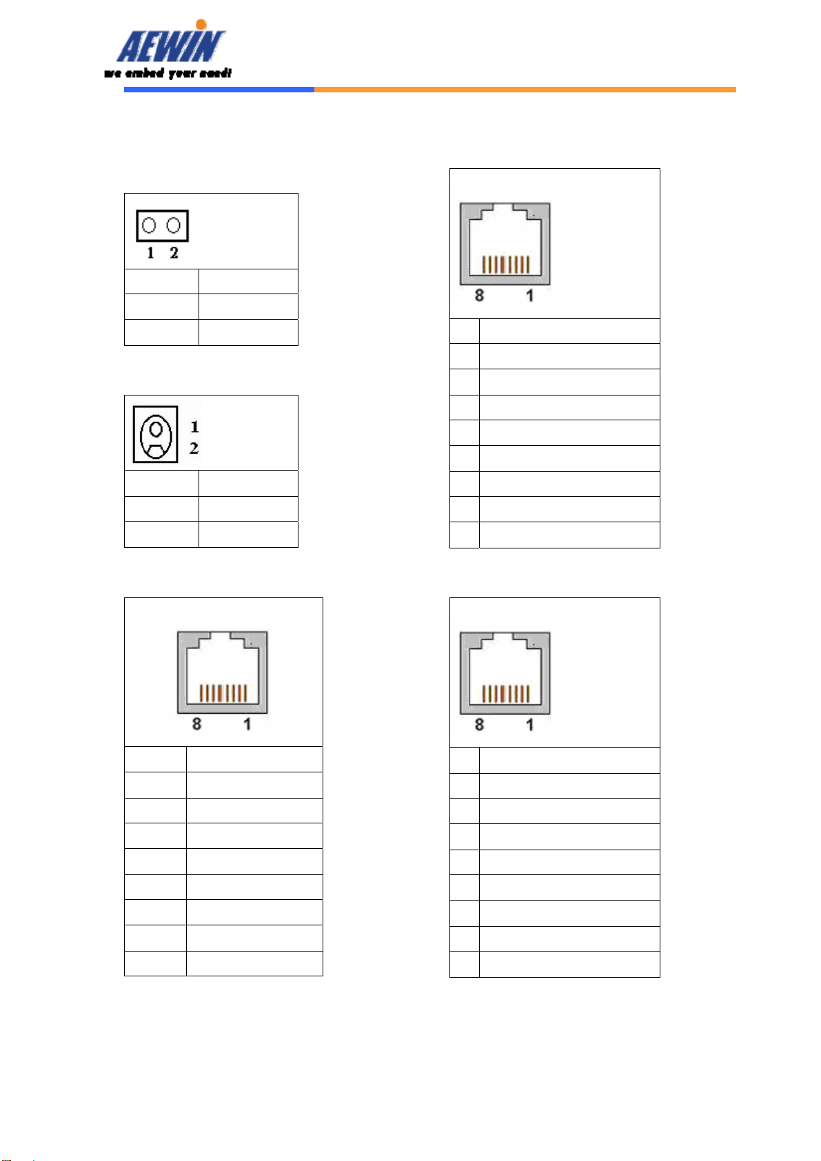
CN1: Reset button
Pin Define
1 Reset #
2 GND
CN2: External power jack
Pin Define
1 +5V
2 Ground
CN3: COM1 RJ45 connector
Pin Define
1 CTS#
2 DTR#
3 TXD#
4 Console Detect#
5 GND
6 RXD#
7 DSR#
8 RTX#
CN4/5/6/7: 10/100 RJ45 connector
Pin Define
1 TX+
2 TX-
3 RX+
4 Chassis Ground
5 Chassis Ground
6 RX-
7 Chassis Ground
8 Chassis Ground
CN8: Four port switch
Pin Define
1 TX+
2 TX-
3 RX+
4 Chassis Ground
5 Chassis Ground
6 RX-
7 Chassis Ground
8 Chassis Ground
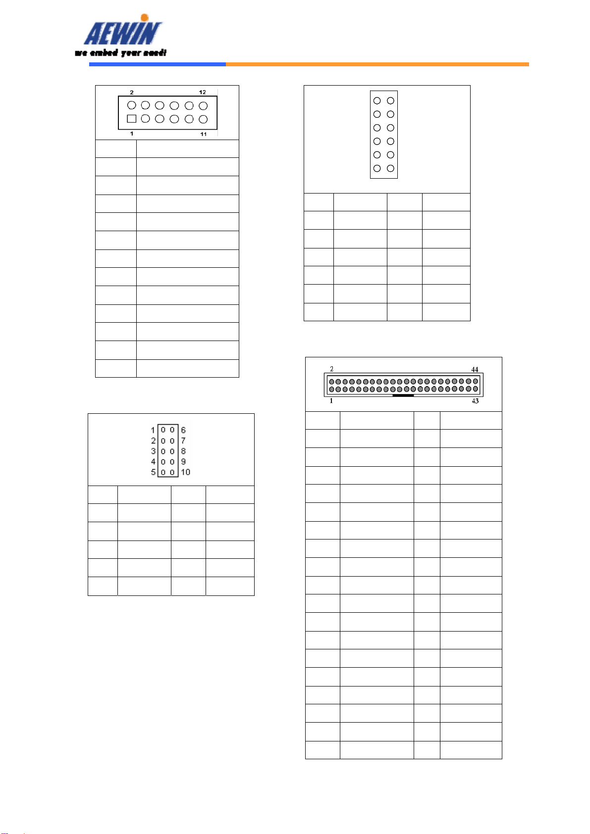
CN10: VGA connector
User’s Manual
AEWIN Technologies Co., Ltd Aug, 2006
12
Pin Define
1 RED
2 GND
3 GREEN
4 +3.3V
5 BLUE
6 GND
7 GND
8 DDC DATA
9 DDC CLK
10 HSYNC
11 VSYNC
12 +5V
CN12: COM port pin header
Pin Define Pin Define
1 DCD# 6 DSR#
2 RXD# 7 RTS#
3 TXD# 8 CTS#
4 DTR# 9 RI#
5 Ground 10 NC
CN13: LPC bus connector
The connector is proprietary for LPC
port 80 card.
Pin Define Pin Define
1 VCC3 2 LAD0
3 LAD1 4 LAD2
5 LAD3 6 LFRAME#
7 PCIRST# 8 VCC
9 CLK 10 KEY PIN
11 GND 12 GND
CN14: 44 Pin 2.0mm pitch IDE
Pin Define Pin Define
1 RSTPIDE# 2 Ground
3 PDD7 4 PDD8
5 PDD6 6 PDD9
7 PDD5 8 PDD10
9 PDD4 10 PDD11
11 PDD3 12 PDD12
13 PDD2 14 PDD13
15 PDD1 16 PDD14
17 PDD0 18 PDD15
19 Ground 20 NC
21 PDDREQ 22 Ground
23 PDIOW# 24 Ground
25 PDIOR# 26 Ground
27 PDIORDY 28 Ground
29 PDDACK# 30 Ground
31 IRQ14 32 V5P0
33 PDA1 34 PD66#
35 PDA0 36 PDA2
1
3
5
7
9
11
2
4
6
8
10
12
1
3
5
7
9
11
2
4
6
8
10
12

User’s Manual
AEWIN Technologies Co., Ltd Aug, 2006
13
37 PDCS#1 38 PDCS#3
39 PIDELED 40 Ground
41 V5P0 42 V5P0
43 Ground 44 N/C
CN15: PS/2 Keyboard & Mouse
Pin Define Pin Define
1 KCLK 2 MCLK
3 KDAT 4 MDAT
5 Key Pin 6 NC
7 PS2_GND 8 PS2_GND
9 PS2_VCC 10 PS2_VCC
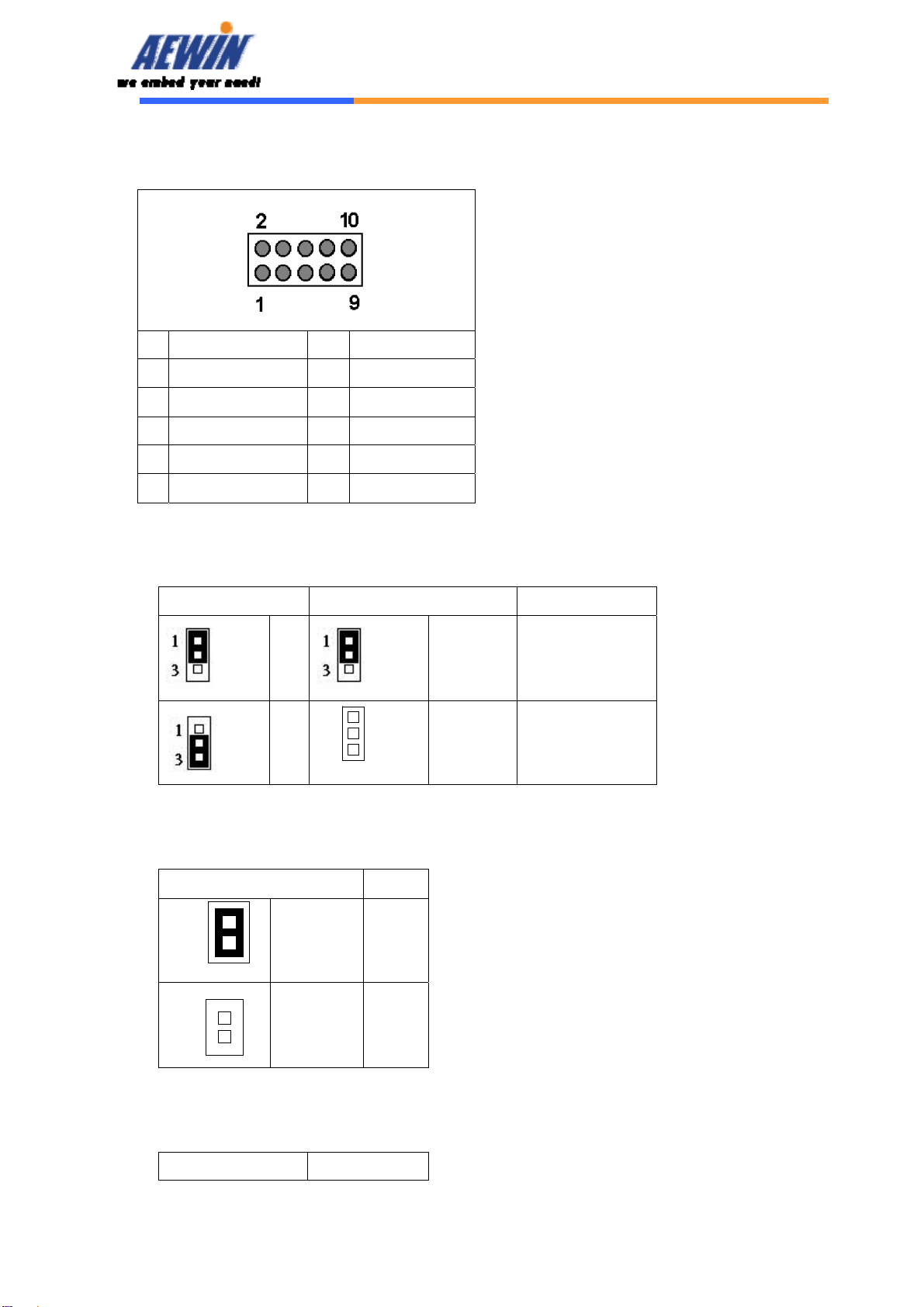
CN16: GPIO
Pin Define Pin Define
1 +5V 2 GPIn0
3 GPin1 4 GPIn2
5 GPin3 6 GPout0
7 GPout1 8 GPout2
9 GPout3 10 GND
CN17: USB pin header
Pin Define
1 VSBVCC
2 DATA-
3 DATA+
4 GND
5 GND
CN18: LAN LED (Optional)
Pin Define Pin Define
1 LINK 1+ 2 LINK1-
3 SPEED1+ 4 SPEED1-
5 LINK2+ 6 LINK2-
7 SPEED2+ 8 SPEED2-
9 N/C 10 N/C
CN19: LAN LED (Optional)
Pin Define Pin Define
1 LINK 3+ 2 LINK3-
3 SPEED3+ 4 SPEED3-
5 LINK4+ 6 LINK4-
7 SPEED4+ 8 SPEED4-
9 N/C 10 N/C
C20: Switch LED (Optional)
Pin Define Pin Define
1 Switch 1 LINK+ 2 Switch 1 LINK-

User’s Manual
AEWIN Technologies Co., Ltd Aug, 2006
14
3 Switch 1
SPEED+
4 Switch 1 SPEED-
5 Switch 2 LINK+ 6 Switch 2 LINK-
7 Switch 2
SPEED+
8 Switch 2 SPEED-
9 Switch 3 LINK+ 10 Switch 3 LINK-
User’s Manual
AEWIN Technologies Co., Ltd Aug, 2006
15
C21: Switch/Power/HDD LED
Pin Define Pin Define
1 Switch 3 SPEED+ 2 Switch 3 SPEED-
3 Switch 4 LINK+ 4 Switch 4 LINK-
5 Switch 4 SPEED+ 6 Switch 4 SPEED-
7 IDE ACTIVE+ 8 IDE ACTIVE-
9 PW LED+ 10 PW LED-
JP1/JP4: DDR Speed & Voltage Detect
JP1 JP4 Setting
1-2
1-2 (ON) DDR-400/2.6V
2-3 1-2 (OFF) DDR-333/2.5V
JP2: Compact Flash Select
Pin Setting
1-2 (ON) Master
(Default)
1-2 (OFF) Slave
JP3: Clear CMOS
Pin Setting
1
3
1
3
1
2
1
2
1
2
1
2

User’s Manual
AEWIN Technologies Co., Ltd Aug, 2006
16
1-2 Normal
(Default)
2-3 Clear CMOS

User’s Manual
AEWIN Technologies Co., Ltd Aug, 2006
17
Chapter 3 BIOS Setup
The ROM chip of your SCB-6971 board is configured with a customized Basic
Input/Output System (BIOS) from Phoenix-Award BIOS. The BIOS is a set of
permanently recorded program routines that give the system its fundamental
operational characteristics. It also tests the computer and determines how
the computer reacts to instructions that are part of programs.
The BIOS is made up of code and programs that provide the device-level
control for the major I/O devices in the system. It contains a set of routines
(called POST, for Power-On Self Test) that check out the system when you turn
it on. The BIOS also includes CMOS Setup program, so no disk-based setup
program is required CMOS RAM stores information for:
zDate and time
zMemory capacity of the main board
zType of display adapter installed
zNumber and type of disk drives
The CMOS memory is maintained by battery installed on the SCB-6971 board.
By using the battery, all memory in CMOS can be retained when the system
power switch is turned off. The system BIOS also supports easy way to
reload the CMOS data when you replace the battery of the battery power lose.
3.1 Quick Setup
In most cases, you can quickly configure the system by choosing the following
main menu options:
1. Choose “Load Optimized Defaults” from the main menu. This loads the
setup default values from the BIOS Features Setup and Chipset Features
Setup screens.
2. Choose “Standard COS Features” from the main menu. This option lets
you configure the date and time, hard disk type, floppy disk drive type,
primary display and more.
3. In the main menu, press F10 (“Save & Exit Setup”) to save your changes
and reboot the system.

User’s Manual
AEWIN Technologies Co., Ltd Aug, 2006
18
3.2 Entering the CMOS Setup Program
Use the CMOS Setup program to modify the system parameters to reflect the
options installed in your system and to customize your system. For example,
you should run the Setup program after you:
zReceived an error code at startup
zInstall another disk drive
zUse your system after not having used it for a long time
zFind the original setup missing
zReplace the battery
zChange to a different type of CPU
zRun the Phoenix-Award Flash program to update the system BIOS
Run the CMOS Setup program after you turn on the system. On-screen
instructions explain how to use the program.
Enter the CMOS Setup program’s main menu as follows:
1. Turn on or reboot the system. After the BIOS performs a series of
diagnostic checks, the following message appears:
“Press DEL to enter SETUP”
2. Press the <DEL> key to enter CMOS Setup program. The main
menu appears:

User’s Manual
AEWIN Technologies Co., Ltd Aug, 2006
19
3. Choose a setup option with the arrow keys and press <Enter>. See
the following sections for a brief description of each setup option.
In the main menu, press F10 (“Save & Exit Setup) to save your changes
and reboot the system. Choosing “EXIT WITHOUT SAVING” ignores
your changes and exits the program. Pressing <ESC> anywhere in the
program returns you to the main menu.
3.3 Menu Options
The main menu options of the CMOS Setup program are described in the
following and the following sections of this chapter.
STANDARD CMOS FEATURES:
Configure the date & time, hard disk drive type, floppy disk drive type, primary
display type and more
ADVANCED BIOS FEATURES:
Configure advanced system options such as enabling/disabling cache memory
and shadow RAM
ADVANCED CHIPSET FEATURES:
Configure advanced chipset register options such DRAM timing
INTEGRATED PERIPHERALS:
Configure onboard I/O functions
PNP/PCI CONFIGURATION:
Configure Plug & Play IRQ assignments and PCI slots
PC HEALTH STATUS:
Configure the CPU speed and, if the optional system monitor IC is installed,
view system information
LOAD OPTIMIZED DEFAULTS:
Loads optimized BIOS settings
SET USER PASSWORD:
Configure the system so that a password is required when the system boots or
User’s Manual
AEWIN Technologies Co., Ltd Aug, 2006
20
you attempt to enter the CMOS setup program. When you log in with this
password, you will be able to enter the CMOS Setup main menu, but you can
not enter other menus in the CMOS Setup program.
SAVE & EXIT SETUP:
Save changes of values to CMOS and exit the CMOS setup program
EXIT WITHOUT SAVING:
Abandon all CMOS changes and exit the CMOS setup program
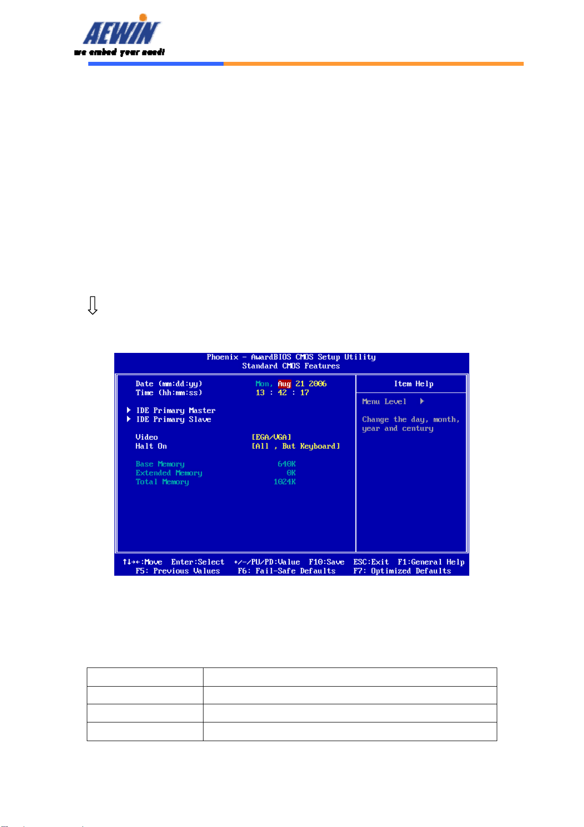
3.4 Standard CMOS Features Setup
Use the Standard CMOS Setup option as follows:
1. Choose “Standard CMOS Features” from the main menu. The following
screen appears:
2. Use the arrow keys to move between fields. Modify the selected field
using the PgUP/PgDN/+/- keys. Some fields let you enter numeric values
directly.
Option Description
Date (mm:dd:yy) Type the current date
Time (hour: min: sec) Type the current time (24-hour clock)
IDE channel Select from “Auto”, “User”, or “None”
Table of contents
Other Aewin Network Hardware manuals

Popular Network Hardware manuals by other brands


Garland
Garland FieldTAP P1GCUA mini user guide

Forcepoint
Forcepoint Pass-through and Mezzanine NIC installation guide

National Instruments
National Instruments GPIB Series Getting started

ASTRON
ASTRON DD-600 Installation and usage manual

Lucent Technologies
Lucent Technologies Stinger MRT Getting started guide

SurfControl
SurfControl 509-8629-00 Setup guide


