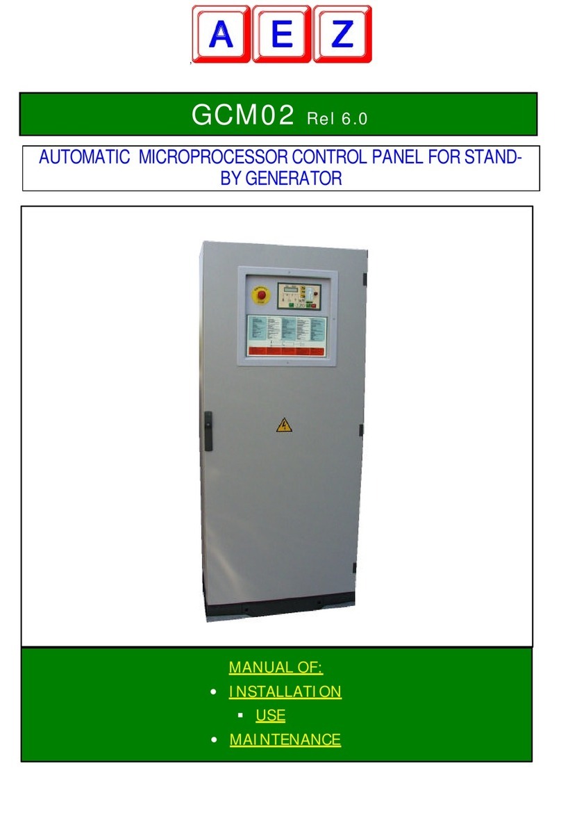
AEZ GCM02 User manual

FILE VER LAST ISSUE LANG. PAGE
GCM02-M-USO-INGLESE.doc SDG/02 18/11/2005 ENG Page 1 of 12
AUTOMATIC MICROPROCESSOR CONTROL PANEL
FOR STAND-BY GENERATOR
MANUAL OF:
Use
Maintenance
GCM02

FILE VER LAST ISSUE LANG. PAGE
GCM02-M-USO-INGLESE.doc SDG/02 18/11/2005 ENG Page 2 of 12
INDEX
DESCRIPTION
PAGE
1.1. PURPOSE 2
1.2. OPERATING PRINCIPLE 4
1.3. VIEW OF THE GCM-02 UNIT 5
1.4. FUNCTIONAL DESCRIPTION OF THE PANEL COMPONENTS 6
1.5. CONTROLS AND OPERATING 8
1.6 PROGRAMMING 10
1.7 VARIOUS COMMANDS 10
1.8 SPECIAL FUNCTIONS
1.9 SIMPLE MAINTENANCE OPERATIONS
11
USER MANUAL
INTRODUCTION
We congratulate with you for the purchase of the GC-M02 control panel to handle your generator unit.
Throughout this manual you will appreciate the remarkable performances and the different applications
granted by the high technology the control panel contains.
This electronic microprocessor module completely controls not only the generator and its switching but it is
also prearranged for the direct serial communication with a PC or, using a GSM unit ,your generator can be
completely remote controlled from miles away.
The M02 unit is equipped with a complete set of digital testers which permits to monitor all mains, generator
and motor parameters.
In order to make you use the group immediately, the manual is divided in two parts:
The first USER MANUAL part has been prepared to provide a clear and simple guide in order to help you
using the generator quickly, completely and safely.
The second TECHNICAL MANUAL part is complete and detailed in order to permit a proper start up to the
qualified personnel.
1.1 PURPOSE
The manual has been especially prepared for the generator user.
All the information necessary for the following points are provided:

FILE VER LAST ISSUE LANG. PAGE
GCM02-M-USO-INGLESE.doc SDG/02 18/11/2005 ENG Page 3 of 12
1. to know the operating principle of the unit;
2. to understand the control panel signals;
3. to handle it during the different service operations;
4. to carry out the basic checks necessary to ensure the efficiency of the generator itself.
Technical or adjustment matters have not been considered. The installer is in charge for them when setting up
the system.

FILE VER LAST ISSUE LANG. PAGE
GCM02-M-USO-INGLESE.doc SDG/02 18/11/2005 ENG Page 4 of 12
1.2 OPERATING PRINCIPLE
HOW A STAND-BY GENERATOR UNIT WORKS
Fig. 1 illustrates the system components that consist of a public mains R, a generator unit G-M, a QGE
command and control panel with a built-in mains contact maker CR, a generator unit contact maker CG
and the M02 module that controls the system.
Supposing that the mains R is within the normal limits, the CR mains contact maker is closed therefore the
utility is powered from the mains. The M02 module controls the R mains and if there should be a drop in
voltage, for a phase lack or in case of dissymmetrical phases, the control panel:
1. opens the CR mains contact maker;
2. operates the start of the G-M generator unit, which, when reached the established operating conditions ,
the M02 module closes the CG contact maker that then powers the utility from the generator unit G;
3. When running, the M motor and G generator are safeguarded against possible anomalies, which could
cause the immediate generator stop and the written recording of the alarm cause on the display (i.e. low
oil pressure, overload and so on);
4. When the R mains is restored within the normal limits, the M02 after a fixed delay, opens the contact
maker of the CG generator and one second later closes the CR contact maker, powering the utility from
the mains again;
5. The generator continues working for at least another minute to cool down and after that it stops
automatically;
6. Even when the generator is not working, some safety devices relating to the fuel and water level are
operating and if an anomaly is detected an alarm status is triggered. The switching of the mains/generator
is also constantly controlled and in case of overload on the mains contact maker an alarm buzzer is
triggered.
To ensure the perfect generator working order, an automatic battery charger maintains the battery perfectly
efficient. An automatic fuel filling system constantly keeps the correct level in the daily tank. A pre-heating
system maintains an ideal temperature to the motor so that it is ready to start whenever necessary.
G
CR CG
GC-M02
M
Fig. 1
UTILITY
QGE
R

FILE VER LAST ISSUE LANG. PAGE
GCM02-M-USO-INGLESE.doc SDG/02 18/11/2005 ENG Page 5 of 12
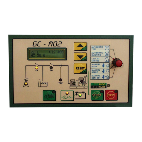
1.3 VIEW OF THE GC-M02 UNIT
Functional description of the block diagrams.
Alphanumerical display showing all the
parameters together with the literal description
of the type of alarm (i.e. FUEL RESERVE)
+/- p.buttons used to select the
parameters and Reset p.button used to
reset functions or alarms
Programming switch:
1 Automatic test. (T)
2 Automatic running. (A)
3 Locked - logic disabled.
4 Forced power supply from mains (CR)
5 Manual starting enabled.
6 Forced power supply from generator (CG).
Status of the mains and
mains/generator switching
Manual control of the
fuel pump
Differential safety device
tripped
When flashing it points out
that the microprocessor is
processing a function.
2 buttons used to start or
sto
p
manuall
y
.
Generator running and motor
alarm indicators
Battery charger
and batteries
powered

FILE VER LAST ISSUE LANG. PAGE
GCM02-M-USO-INGLESE.doc SDG/02 18/11/2005 ENG Page 6 of 12
Description of the components.
Programming switch.
Type of operational mode selection
1. Automatic test (T)
2. Standard automatic running (A)
3. Locked status – electronics disabled, used for
maintenance.
4. Utility power supply forced from mains (CR).
5. Enable start push button to start in manual mode.
6. Utility power supply forced from generator (CG).
Display reading selection push buttons.
These are used to select the reading page required and to
program the weekly timer.
Reset/Enter push button: resetting of the functions and
elimination of alarm status , confirms parameters entered in
the programming phase. An impulse cut out the acoustic
alarm, 2 impulses to reset.
DESCRIPTION OF MEASUREMENT PAGES
When the mains power is connected these values are
automatically displayed .They shows the mains voltage and
frequency.
The three voltages values (one per phase) between one
phase and another are displayed for a detailed control of the
mains.
and the three star voltages between phase and neutral
When the generator starts running, the display will
automatically show the measurements such as frequency,
voltage and current on phase 1, relative to the generator.
1.4 FUNCTIONAL DESCRIPTION OF THE GC MO2 CONTROL PANEL
COMPONENTS
1
2
3
4
5
6

FILE VER LAST ISSUE LANG. PAGE
GCM02-M-USO-INGLESE.doc SDG/02 18/11/2005 ENG Page 7 of 12
The three phase voltages between one phase and another
are displayed for the detailed control of the generator.
and the three star voltages between phase and neutral
The three phase currents are used to check the load status on the
individual phase.
The capacities indicate the load status and type on the generator:
KVA = kilovoltamper = apparent capacity; KW = kilowatt = actual
capacity; KVAr = kilovar = reactive capacity.
Cosfì = power factor = phase displacement an
g
le between volta
g
e and
current, with the normal load it indicates L – 0,…. If the load is
capacitive it indicates C + 0,… dangerous situation for the correct
running efficiency of the generator, it means that the automatic re-
phasin
g
is enabled; the same has to be disabled when the
g
enerator i
s
running.
The voltage of the battery and the load current are indicated with the
mains connected, generator stopped and current inferior to 2 A the
voltage must not exceed 13,5 V for the 12V batteries and 27V for the
24V batteries, when the generator is running, voltages are higher as
they are conditioned by the battery charger generator.
RPM = motor revs. LC = fuel percentage in tank.
PO = oil pressure. TM = motor temperature. Warning: LC, PO and
TM are displayed only if the corresponding probes are connected.
Total hour meter. The parameter is constantly saved even if
the battery is disconnected.
This indicates the status of the inputs and is exploited by the
installation engineers when setting-up the system.
This indicates the status of the outputs and is exploited by
the installation engineers when setting-up the system.
Weekly timer. It resets each time the battery is disconnected and is
used to run the automatic test, the automatic system lock and the
reserve units, see programming.

FILE VER LAST ISSUE LANG. PAGE
GCM02-M-USO-INGLESE.doc SDG/02 18/11/2005 ENG Page 8 of 12
This block diagram indicates the status of the system which powers the
utility.
The trestle illustrates the public mains. The lit LED indicates that the
three phases are within the fixed parameters and vice versa when it is
switched off.
The two CG and CR led indicate which contact maker is closed to power
the utility.
The TRIP led indicates that the differential protection intervention. If it
flashes, it means that there is a leak higher 50% higher than the fixed
parameter. The led on the generator indicates that the generator is
running.
The led on the motor indicates the alarm status of the generator.
Battery charger and battery.
The led indicate that the battery charger is powered and that
the MO2 module is powered by the battery.
The WAIT/PROG led indicates that the micro-controller is
processing. When it stops flashing the processing result will
be obtained; for example, when the led on the mains trestle
is on, it means that the mains has returned within the normal
limits. However the generator CG only switches back to the
mains CR following a settling delay. The WAIT/PROG led
flashes during this delay phase.
The M02 module is equipped with automatic control of the
fuel re-fuelling pump. When it is running the led is on and
the push button is used to its manual control .
Motor starting push button. It is enabled only when the
programming switch is set on 5 MANUAL START. The
control is direct; release the push button once the motor is
running and the led indicates star up in process.
Stop push button that is always enabled. It has to be
pressed until the complete stop of the motor. The led
indicates the motor stop in process.

FILE VER LAST ISSUE LANG. PAGE
GCM02-M-USO-INGLESE.doc SDG/02 18/11/2005 ENG Page 9 of 12
1.5 CONTROLS AND OPERATING
The operational modes that can be selected with the programming switch are six, namely:
1. Automatic test: This starts to test the generator without disconnecting the mains power supply from the
utility. When the switch is turned back to automatic mode the generator stops following a delay of roughly
one minute (it is used for periodic tests or to check the running efficiency after the maintenance).
2. Automatic mode; if there should be a failure in the mains the circuit board responds by opening the
mains contact maker. If the generator fails to start another 4 starting attempts are made. 10 seconds
after the start the generator powers the utility. While running the generator and motor are constantly
controlled and a possible anomaly is immediately displayed (examples: fuel reserve, water level,
overload, min. voltage etc.) and the relative stopping cycle is triggered. Once the mains is re-connected,
after the set time, the utility is switched back to the mains and the generator is stopped following a delay
of roughly one minute to allow it to cool down (this is the normal operational situation ).
3. Lock: this sets the generator in a locked status. It disables every possibility of starting while the mains
power the utility. This mode is used to work on the system safely, being certain that the generator will not
start even if the mains should be disconnected ( it is used during maintenance).
4. Manual mains: it permits having the forced power supplied from the mains in case of command and
control electronics breakdowns as well (it is used when the generator is left inactive).
5. Manual starting: this allows the manual start of the generator using the start push button. The control is
direct without the involvement of electronic components. It ensures the operation of the generator even
when the electronics are faulty (it is used for the manual emergency controls or for maintenance
purposes).
WARNING
When the programming switch is in this position, all the utility circuits of the generator, such as the
solenoid valves, electronic rpm regulators etc, are powered . In case the switch is left by mistake in this
position with the generator stopped, the starting battery would run flat very quickly.
6. Manual generator: it permits the forced power to be supplied from the generator (it is available for
manual operations or in the case of automatic functions breakdown).
STOP
This is always enabled in every situation.
The button has to be pressed till the motor stop

FILE VER DATA ULT. VERSIONE LINGUA PAGINA
GCM02-M-USO-INGLESE.doc SDG/02 18/11/2005 ITA Page 10 of 12
EMERGENCY STOP
If pressed, the red mushroom push button, placed in the middle of the door, stops the generator immediately and opens
the contact maker of the generator (CG) causing the block of the group..
To release the emergency status, set the programming switch in Lock position, turn the emergency push button and pull it
up.
FUEL PUMP CONTROL (on request)
The M02 module electronically controls the fuel level. It automatically controls the fuel pump so that the daily tank
requirements are constantly ensured. A push button enables the pump direct control with only a maximum safety level
safety function.
WAIT/PROG
A new conceived and remarkably useful LED has been fitted on the GCM02 module to assist the operator, namely the
WAIT/PROG LED. This LED flashes each time the timer is triggered informing the operator what is happening even over
long timing periods.
All LED are provided with a synoptic that makes the control panel easy to comprehend.
SUMMARY
The unit is normally programmed in AUTOMATIC mode.
When operating, the generator must be set in the LOCKED status.
If the generator is not to start even if the mains is disconnected it is to be set in the MANUAL MAINS status. The
reason for this is that if, while the generator is not working, there should be a failure in the electronics, the power
supply from the mains would be ensured in any case.
When , in case of mains lack, there is no need to use the generator, it must be always set in the MANUAL MAINS status.
Infact, in case of electronic breakdown- while the generator is not working- the power supply would always been ensured
by the mains.
HOW TO PROCEED IN CASE OF GENERATOR BREAKDOWN.
The alarm status is shown on the display. Whatever the anomaly, the cause is to be found first and then press the RESET
push button. The causes and the solutions differ depending on the type of anomaly involved:
1. Electrical anomalies due to min./max. voltage and frequency. If the anomaly should persist after having pressed the
RESET push button , call for a technical assistance;
2. Anomaly due to a low oil pressure, high motor temperature, low water or oil level, fuel reserve. Check the relative
levels (water, oil, fuel) and top-up if necessary then reset;
3. Anomaly of the dynamo battery charger. In this case request technical assistance;
4. Alarm due to local or remote emergency stop status. Set the programming switch on LOCKED mode, turn and pull the
active emergency push button, then reset;
5. Alarm due to failed starting. Try starting with manual control and advise the supplier;
6. The generator overload protection switch has tripped. It is to be reset manually by a qualified engineer (see simple
maintenance jobs section).

FILE VER LAST ISSUE LANG. PAGE
GCM02-M-USO-INGLESE.doc SDG/02 18/11/2005 ENG Page 11 of 12
1.6 PROGRAMMING
If the electronic module should be disconnected from the power supply, the established weekly timer programming will be
deleted; consequently, all the functions foreseen for the internal timer would fail to work at the time and on the programmed
day, therefore, the weekly timer has to be re-programmed.
When a function - the automatic test, the automatic lock or the automatic start – is enabled, the following screen will appear
on the display in case the battery is not driven any more:
FUNCTIONING OROL…..
Go to the following page re-program it.
Pressing ENTER, the day flashes. Using the +/- keys, modify the day and press ENTER to confirm. The time flashes.
Using the +/- keys modify the time and confirm with ENTER. Do the same for minutes and seconds.
In case of uncomplete programming it is impossible to change the page.
1.7 VARIOUS CONTROLS
LED TEST
Press the + /- push buttons together for 2 seconds. All LEDs, except the start, stop and battery charger LEDs, will light up.
ALARM SILENCING
Press the RESET key for 2 seconds to silence the buzzer alarm.
FUNCTIONS RESET
Press the RESET key for 2 seconds to reset the alarm status and to restore the functions.
1.8 SPECIAL FUNCTIONS
The M02 is preset for some special operating functions such as: automatic test and lock, scheduled maintenance,
remote assistance ecc. if enabled, when they start functioning, on the display a screen, indicating the enabled function,
appears. Some functions influence the set operativeness and need direct interventions in order to use the group.
LOCKED GE
The lock function is principally used when a set operates in town and the emergency is not requested at night. When
locked, in case of mains lack the set will not work. If its intervention is needed, it will be only possible using the manual
Controls.
MAINTENANCE REQUEST
It does not alter the functioning, enables the acoustic alarm status for the fixed time and shows the word MAINTENANCE
on the display.

FILE VER LAST ISSUE LANG. PAGE
GCM02-M-USO-INGLESE.doc SDG/02 18/11/2005 ENG Page 12 of 12
REMOTE ASSISTANCE
The group normally operates on automatic running and is remote-controlled.
1.9 SIMPLE MAINTENANCE OPERATIONS
USER SAFETY PROCEDURE
WARNING
It is strictly forbidden to operate on parts under tension.
ELECTRICAL MAINTENANCE
All interventions must be carried out by skilled personnel.
By means of the control unit, all control, check and reset functions are possible from the external .
Proceed as follows to enter the equipment inner to the control panel:
1. Set the programming switch on LOCKED mode.
2. Check the total stop of the unit .
3. Disconnect the mains line that powers the control panel and switch the main ON/OFF switch of the mains on.
4. Check if the mains has been effectively disconnected. It can be seen by the mains OK LED switched off and by the
display switched to the mains that must indicate zero.
5. Open the control panel and check for possible anomalies to:
•fuses;
•automatic switches;
•thermal relays.
Once maintenance has been completed repeat the procedure in reverse order to reset the unit.
MECHANICAL MAINTENANCE
If the generator should fail to start due to a fuel circuit anomaly, and in an emergency status, here are some suggestions.
How to restore the fuel circuit:
1. Set the programming switch on Manual Start mode without starting the generator. In this way the 15/54, that
powers the fuel interception solenoid valve, is activated.
2. Once filled up with fuel, enable the hand pump situated on the motor until the circuit restoration. The restoration is
reached when the pump becomes harder and harder to move.
3. Start in manual mode ( We suggest to restrict the starting attempts to 10 seconds each with a pause of 15 seconds
in-between to allow the battery to recover efficiently). Once the unit has started and is regularly running, reset the
automatic functions.
PERIODIC CHECKS
To keep the unit in working order, some periodic checks must be made together with those scheduled by the motor
manufacturer and by the installation engineer:
1. check the electrolytic level of the battery every 15 days after the installation and request the assistance of an engineer
if an excessive consumption is noticed. After the initial period, check every 30 - 60 days;
2. generators equipped with pre-heating system motor, check if the motor is hot each time a check is made otherwise
request technical assistance. (WARNING: a cold motor at low temperatures could have difficulty in starting or outputting
once started);
3. If the generator is rarely triggered due to the lack of mains power supply execute an automatic test for at least 2
minutes.
4. if new electrical machines are installed in the system powered by the generator, request technical assistance to check
the suitability of the CG/CG mains/generator switching to the new load.
SUMMARY: On a periodic basis, check the electrolytic level of the clear batteries. Touch the motor to realize if it is
hot (if equipped with pre-heating system) and execute an automatic test.
Other manuals for GCM02
2
Other AEZ Control Panel manuals
Popular Control Panel manuals by other brands

Siemens
Siemens SIMATIC HMI KP300 Basic mono PN operating instructions
Enovation Controls
Enovation Controls Murphy PowerCore MPC-10 Operation manual

Certikin
Certikin CTX Operating instructions and maintenance

IDS
IDS 1632 user manual

ROEL
ROEL Cerber C62 Programming manual

Vents
Vents KV TwinFresh Wi-Fi user manual
Intermatic
Intermatic PE30000 Series Installation, operation & service manual

Hills
Hills Reliance 8 Installation & programming manual

GARDTEC
GARDTEC 800 Engineer’s Reference Guide
Johnson Controls
Johnson Controls Qolsys IQPK048 installation manual

Riedel
Riedel CCP1116 quick guide
Siemens
Siemens SINAMICS BOP-2 operating instructions
