AFA STAINLESS AFLZ02 User manual
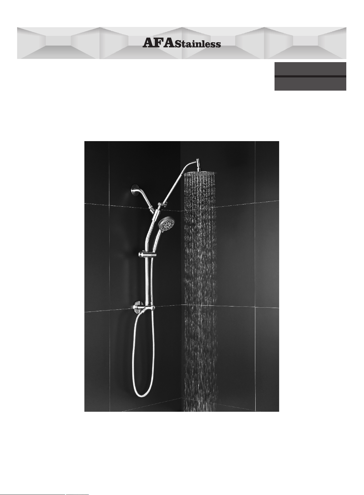
MULTI-FUNCTION HAND HELD & RAIN HEAD SHOWER SYSTEM
Owners Manual
AFLZ02
AFA USA LLC
3190 Airport Loop Dr Ste B1, Costa Mesa, CA 92626
Toll Free: (877) 778-6888 English Speaking Only
Monday-Friday 9 a.m-5 p.m Pacific Time Zone
Email: customer.service@afastainless.com
Français P.21
Español P.41

SAFETY INFORMATION
Please read and understand this entire manual before attempting to
assemble, operate or install the product. Before beginning the assembly of
this product, compare the parts with the package contents and list. If any
part is missing or damaged do not attempt to assemble the product and
contact AFA Stainless customer service for assistance.
WARNING
• Follow the installation instructions carefully. Proper installation is the
installer’s responsibility.
CAUTION
• Check local building codes before beginning installation to ensure
compliance.
This unit meets or exceeds the following:
• ASME A112.18.1/CSA B125.1
• California Title 20 Water-Efciency Standards
• Listed by CUPC for use in the US and Canada
• Listed by California Energy Commission
2
AFA STAINLESS PRODUCT SUPPORT TEAM
Customer service hotline
Toll Free: (877) 778-6888 English Speaking Only
Monday-Friday 9 a.m-5 p.mPacific Time Zone
Email: customer.service@afastainless.com
AFA USA LLC
3190AirportLoopDrSteB1,CostaMesa,CA92626
Flow rate Showerhead
1.8GPM(6.8L/M)-MAX ASME A112.18.1/CSA B125.1
Flow rate Handshower
1.8GPM(6.8L/M)-MAX ASME A112.18.1/CSA B125.1
MULTI-FUNCTION HAND HELD & RAIN HEAD SHOWER SYSTEM
Owners Manual
AFLZ02

3
DIMENSIONS:
(H)32-1/8" [815MM] × (W) 20-7/8" [532MM]
Hand shower hose: 59.05" [1500MM]
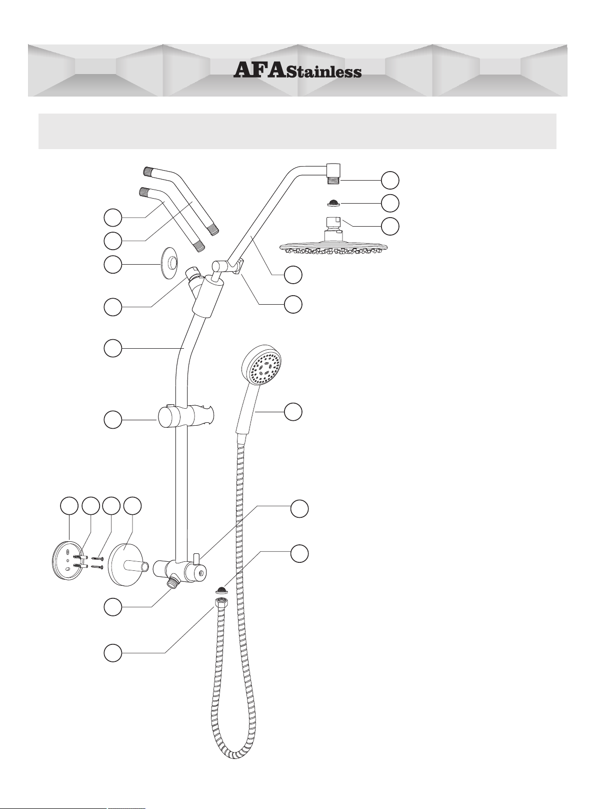
AFLZ02 DRAWING
4
1. 6" Shower Arm
2. 8" Shower Arm
3. Shower Arm Flange
4. Pivot Ball
5. Shower Pipe
6. Adjustable Hand Shower Holder
7. Mounting Face Plate
8. Anchors
9. Screws
10. Bottom Mounting Bracket
11. Bottom Shower joint
12. Hand shower Hose
13. Shower Joint
14. Filter Gasket (Pre-installed)
15. Rain Shower Head
16. Adjustable Shower Arm
17. Shower Arm Adjuster
18. Hand Shower
19. Diverter Valve
PARTSLIST
4
6
11
3
7 9 10
18
13
19
14
17
12
1
2
8
15
14
5
16
5
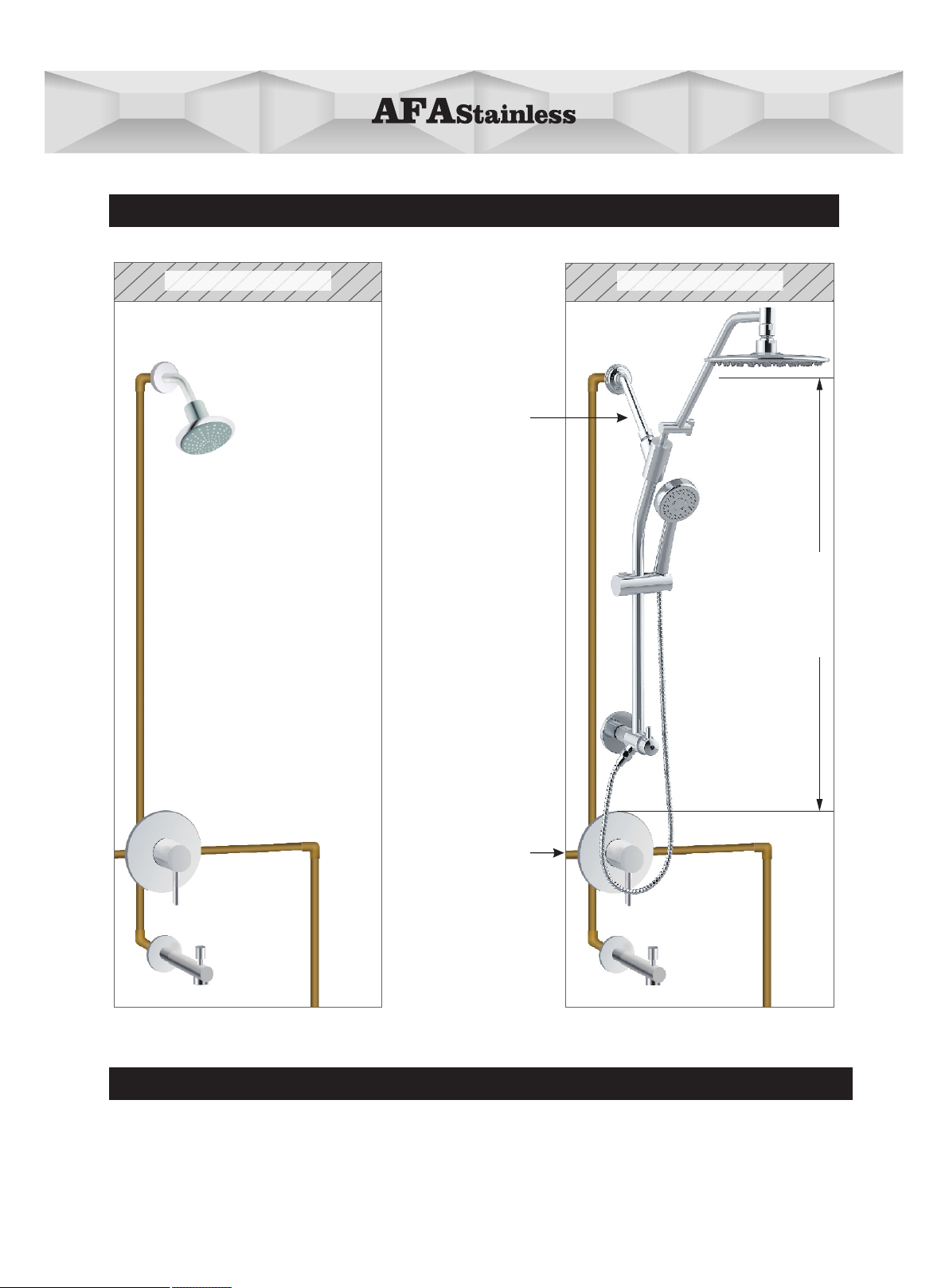
Installation of this product requires the following:
Minimum distance of 25" between the shower arm and the top of the mixing valve trim.
IMPORTANT: please review before installation
Shower Arm
Mixing Valve Trim
(Not Incl.)
min. 25" 63.5cm
BEFORE AFTER
BEFORE YOU BEGIN
Ceiling Ceiling

6
Recommended Tools for Installation:
Silicone SealantLevel
1/4 Inch Bit
Drill Bit
Electric Drill
T-5 T-6 T-7 T-8
Plumber’s Tape
Double Sided Tape ×2
T-1 (Included) T-2(Included) T-3(Included) T-4(Included)
Important Note for Installation
·Before and during installation, please read and familiarize yourself with all installation
instructions for this product.
·Please keep all components, parts and accessories of this product away from small
children and minors. During installation, all screws, tools and small parts should be
supervised so that they do not fall into the hands of children.
·Use caution at all times when installing this product. Please ensure that you are physically
able to perform all parts of the installation and that you have the correct tools and
equipment needed. Before beginning, remove all wrappers and packing materials
including staples and packing straps.
·Please check to ensure that all components and parts are complete.
·NOTE: The Filter Gasket parts #14 must be installed to protect against incoming
sediment as well as water leakage. It is recommended these gaskets be cleaned from
time to time. Please refer to page 17 & 18 “CLEANING AND CARE OF FILTER GASKET”.
Pencil Channel Lock Wrench
T-9 T-10 T-11 T-12
T-13 T-14
Adjustable Wrench
Tape Measure Phillips Screwdriver
1/2" Allen Wrench 3/32" Allen Wrench
Needle-nose Pliers
T-15
Denatured Alcohol
Cloth
T-16
Hammer
INSTALLATION
CAUTION — TIPS FOR REMOVAL OF OLD SHOWER:
Always turn off water supply before removing existing diverter or disassembling the valve.
Open shower handle to relieve water pressure and ensure all water has been drained.
Option 1: Easy Install(No drilling required)
2
7
T-12
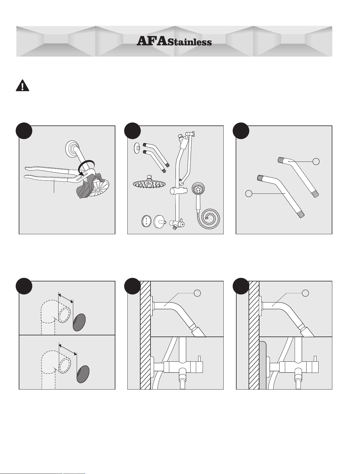
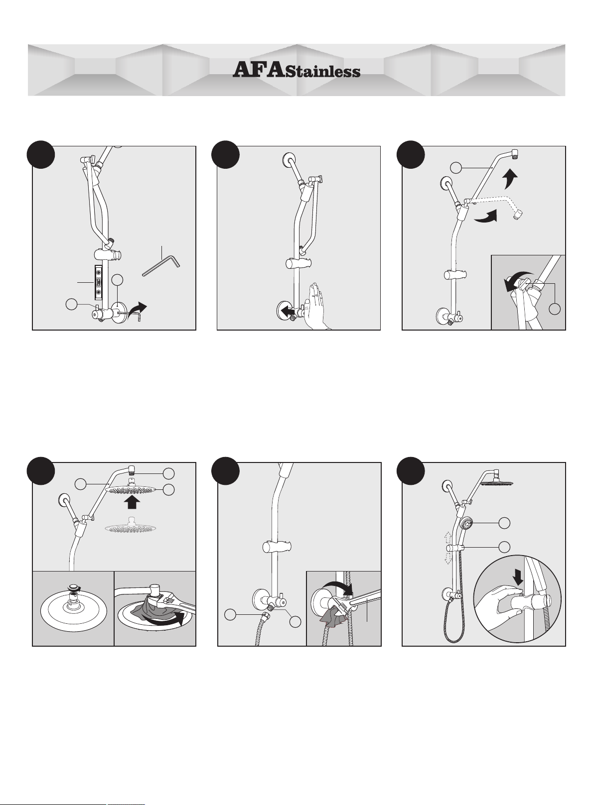
1
Remove the existing showerhead
arm by turning it in a counter
clockwise direction.
Note: A channel lock wrench T-12
(Not included) may be required.
Prepare for installation.
le
ss than 1 -3/8"
1-7/8"-4"
Choosing the correct length of
shower arm.
Measure the distance between the
1/2" - 14 NPT (National Pipe Thread) in
wall water supply elbow (not included)
and the nished wall surface. If the
measurement is less than 1-3/8" choose
6" shower arm (1). If the measurement
is between 1-7/8"-4" choose 8" shower
arm (2).
1
If the wall surface is the same between
the shower arm and the bottom
mounting brocket, use 6" Shower
Arm (1).
2
If installing in a berglass or acrylic
shower enclosure where the shower
arm is mounted on sheet rock or tile,
use 8" Shower Arm (2).
6" Shower Arm
8" Shower Arm
1
2
There are two optional shower arm
for your choosing: 6" Shower Arm (1)
and 8" Shower Arm (2).
3
56
4

8
10 19
Attach Bottom Mounting Bracket (10)
to the back of Diverter Valve (19).
4
Wrap one layer of Plumber's Tape
T-1 (included) onto the threaded lower
side of the shower arm. Connect the
Pivot Ball (4) to the shower arm.
Tighten with Adjustable Wrench (T-13).
T-13
3/32"
10
7
T-3
Insert the Mounting Face Plate (7) into
the Bottom Mounting Bracket (10) and
tighten set screw using the 3/32" Allen
Wrench T-3(Included).
RemovebackingfromDouble Sided
Tape T-4 (Included) and attach to the
at side of Mounting Face Plate (7).
CAUTION: Do not touch the
adhesive side of tape.
double sided tape
7
T-4
T-1
Slide the shower arm through the ange.
Wrap plumber's tape (T-1) clockwise
3 or 4 turns around threaded end of
shower arm. Connect the shower arm
to the wall water supply elbow
(not included) by turning in a
clockwise direction..
Clean the wall area around the
Mounting Face Plate (10) with
Denatured Alcohol T-5 (Not included)
and allow to fully dry.
9
12
1110
8
7
T-1
9
Loosen the wing nut of the Adjustable
Shower Arm (16) and adjust the gear
joint to a suitable height and tighten
the Shower Arm Adjuster (17) wing nut.
16
17
Press rmly to the wall. Allow minimum
of 4 hours for proper adhesion.
Removetheprotectivecapfrom Rain
Shower Head (15). With an Adjustable
Wrench (T-13) and a rag, tighten Rain
Shower Head onto Adjustable Shower
Arm (16).
13
15
16
Place the Hand Shower (18) into Hand
Shower Holder (6). Press the button
and adjust holder to a convenient
height.
18
6
Remove the plastic protective cap
from Bottom Diverter Joint (11), and
connect the end of the Hand Shower
Hose (12). Tighten with Adjustable
Wrench (T-13).
12
11
T-13
3/32"
T-3
10
T-6
19
Use Level T-6 (Not included) to adjust
the bottom of diverter in a 90 degree
vertical position.Tighten set screw
on the side of Diverter Valve (19) with
3/32" Allen Wrench T-3 (Included).
13 15
14
18
17
16

10
Turn on water and test Rain Shower
Head (15) and Hand Shower (18) by
moving the Diverter Valve (19) lever to
ensure there are no connection leaks.
15
18
19

2
If installing in a berglass or acrylic
shower enclosure where the shower
arm is mounted on sheet rock or tile,
use 8" Shower Arm (2).
le
ss than 1 -3/8"
1-7/8"-4"
If the wall surface is the same between
the shower arm and the bottom
mounting brocket, use 6" Shower
Arm (1).
T-12
Remove the existing showerhead
arm by turning it in a counter
clockwise direction.
Note: A channel lock wrench T-12
(Not included) may be required.
Prepare for installation.
6" Shower Arm
8" Shower Arm
1
2
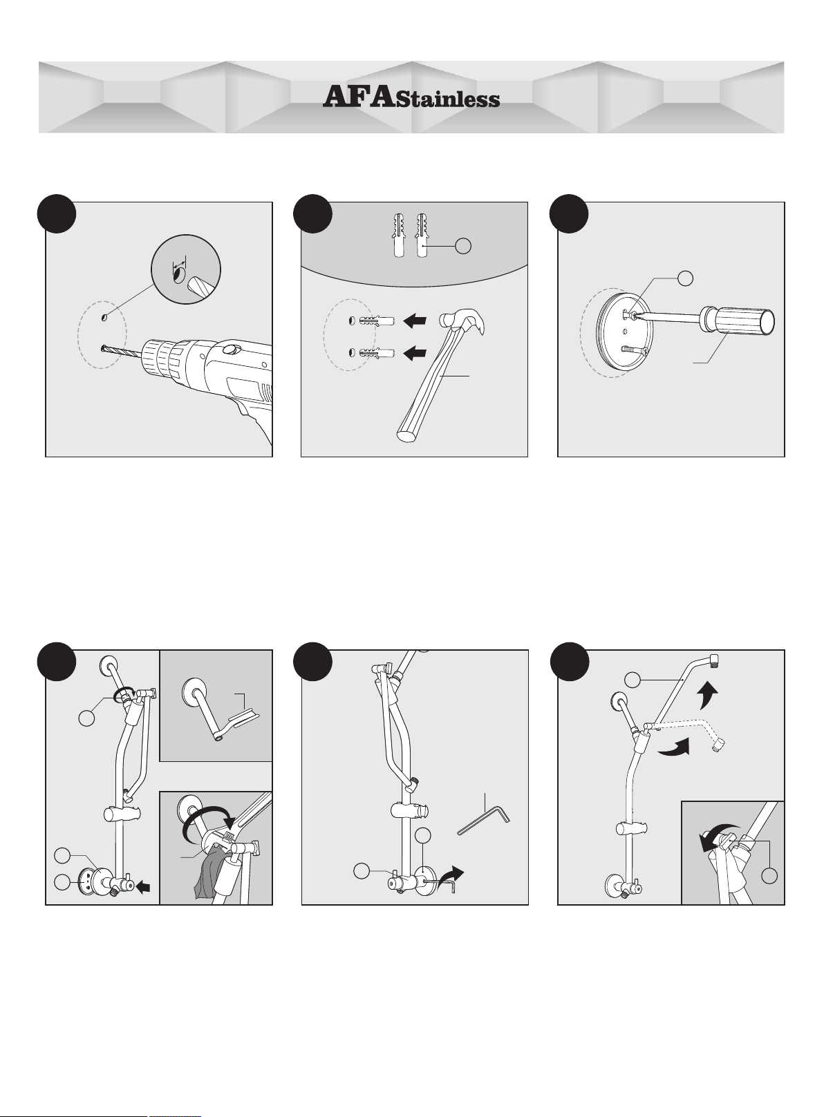
INSTALLATION
Option 2 Permanent Installation(Drilling required)
2
11
13
1
56
4
There are two optional shower arm
for your choosing: 6" Shower Arm (1)
and 8" Shower Arm (2).
Choosing the correct length of
shower arm.
Measure the distance between the
1/2" - 14 NPT (National Pipe Thread) in
wall water supply elbow (not included)
and the nished wall surface. If the
measurement is less than 1-3/8" choose
6" shower arm (1). If the measurement
is between 1-7/8"-4" choose 8" shower
arm (2).

12
T-6
Use Level T-6 (Not included) to adjust
the bottom of diverter in a 90 degree
vertical position.
2
1
7
Place Mounting Face Plate (7) on the
wall and use Pencil T-11 (Not included)
to mark center screw holes on wall.
CAUTION: Before marking holes,
apply duct or masking tape over the
surface area of the tile where the hole
is to be drilled. This helps to prevent
the drill bit from slipping when starting
to drill the hole.
10
19
Connect the Bottom Mounting
Bracket (10) into the back of Diverter
Valve (19).
Hand tightenthe Pivot Ball (4) to
Shower Arm (1 or 2).
4
T-11
Draw circle around Bottom Mounting
Bracket (10) with Soft Pencil T-11
(Not included). Unscrew the Pivot Ball
(4) Remove the Shower Pipe (5).
4
5
10
10 12
11
9
78
Slide the shower arm through the ange.
Wrap plumber's tape (T-1) clockwise
3 or 4 turns around threaded end of
shower arm. Connect the shower arm
to the wall water supply elbow
(not included) by turning in a
clockwise direction..
13
Place tip of the drill bit (1/4") against
the mounting hole mark on the wall or
the masking tape. Drive the drill bit
through each mounting hole mark.
CAUTION: Do not drill into a water line!
1/4”
(6mm)
Insert Screw Anchors (8). And gently
tap anchors into the holes with
Hammer T-14 (Not included).
8
T-14
×2
9
T-10
Use Philip Screwdriver T-10
(Not included) to gently secure bracket
to wall with 2 screws (9).
7
10
4
Wrap one layer of Plumber's Tape
T-1 (included) onto the threaded lower
side of the shower arm. Connect the
Pivot Ball (4) to the shower arm. Tighten
with Adjustable Wrench (T-13).
Place Mounting Face Plate (7) into
Bottom Mounting Bracket (10).
Tighten set screw on the side of
Diverter Valve (19) with 3/32" Allen
Wrench T-3 (Included).
3/32"
T-3
10
19
17
Loosen the wing nut of the Adjustable
Shower Arm (16) and adjust the gear
joint to a suitable height and tighten
the Shower Arm Adjuster (17) wing nut.
16
181716
15
14
13
T-13
T-1

14
13
15
16
T-13
T-13
Remove the plastic protective cap
from Bottom Diverter Joint (11), and
connect the end of the Hand Shower
Hose (12). Tighten with Adjustable
Wrench (T-13).
12
11
Place the Hand Shower (18) into Hand
Shower Holder (6). Press the button
and adjust holder to a convenient
height.
18
6
21
20
19
15
18
22
Removetheprotectivecapfrom Rain
Shower Head (15). With an Adjustable
Wrench (T-13) and a rag, tighten Rain
Shower Head onto Adjustable Shower
Arm (16).
Turn on water and test Rain Shower
Head (15) and Hand Shower (18) by
moving the Diverter Valve (19) lever to
ensure there are no connection leaks.

INSTRUCTIONS
handle
Flow to
Hand shower Flow to
Showerhead
MULTI-FUNCTION HAND SHOWER
Adjustable spray patterns Wide Rain/Power Massage/Stay-Warm Mist
DIVERTER
• To use the rain showerhead, turn the handle to the right position.
• To use the hand shower, turn the handle to the left position.
function lever
Wide Rain
Power Massage
Stay-Warm Mist
15
handle

Adjust Rain Shower Head
NOTE: Adjust shower head up or down to a desired angle with an adjustable wrench.
1 2
Adjust Hand Held Shower
4
To adjust the angle of hand held shower, simply turn
the hand shower in either direction.
16
3
Press button on Hand Shower Holder (6)and then
slide up or down the shower pipe to the desired
height.
Note: Tighten to desired rmness.
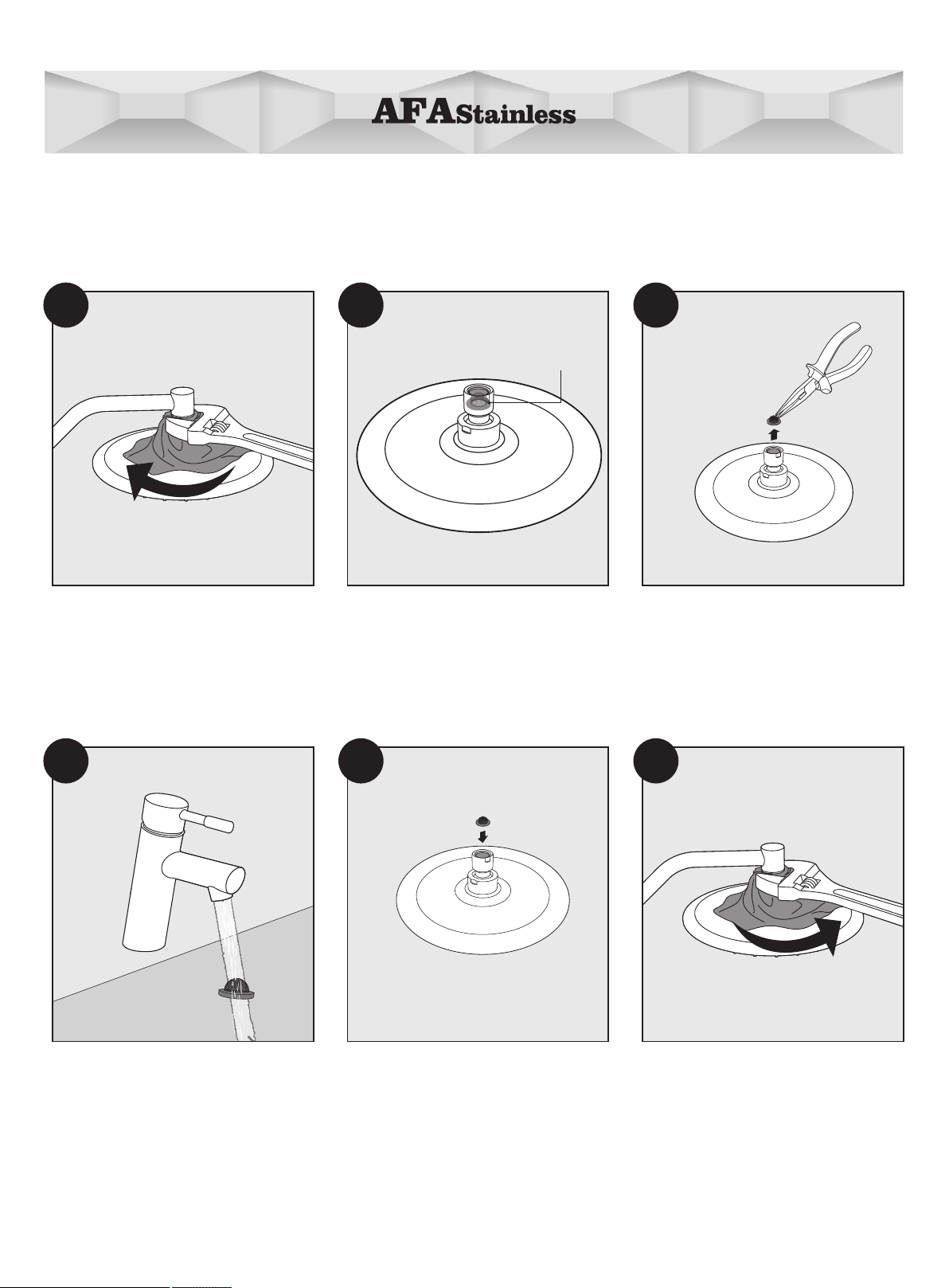
Filter
gasket
1 2 3
4 5
With an adjustable wrench and rag,
remove the showerhead from the
shower arm by unscrewing the ball
joint in a counter-clockwise direction.
The lter gasket is located at the
opening of the showerhead ball
joint.
Remove the lter gasket from the ball
joint. If necessary, use needle-nose
pliers (not provided) and set aside.
Flush the lter gasket with water. Reinstall the lter gasket into the ball
joint threads.
CLEANING AND CARE OF FILTER GASKET
17
Clean the left over Plumber’s Tape
from shower spout threads and apply
a new single layer of plumber’s tape.
Reattach the showerhead by screwing
the ball joint clockwise into the shower
spout threads. Tighten with an
adjustable wrench and rag.
6

1 2 3
With an adjustable wrench and rag,
remove the hand shower hose from
the bottom of diverter valve in a
counter-clockwise direction.
The lter gasket is located in the
bottom of the hose.Remove the lter
gasket from the hose. If necessary,
use needle-nose pliers (not provided).
Take care not to use excessive force
when grasping the lter gasket to
avoid potential damage.
Flush the lter gasket with water.
4
Reinstall the lter gasket into the
hose.
18
5
Connect this end of the hose to
the bottom of diverter valve.

AFA Stainless uses high quality silicon nubbins that ensure a consistent, even distributed water spray.
Note: In areas that have hard water, its common to have Calcium and Lime deposits clog up the nubbins.
Please refer to the Cleaning & Care Instructions.
CLEANING & CARE
1 2
1
When the holes are clogged due to
mineral deposits, touch the silica
nubbins with your nger to loosen
deposits.
Run water through the showerhead
for several minutes to remove debris.
2
Run water through the hand shower
for several minutes to remove debris.
When the holes are clogged due to
mineral deposits, touch the silica
nubbins with your nger to loosen
deposits.
19

20
– Please ensure that the surface of your AFA product has cooled down before cleaning (clean at room temperature).
– Use a soft cloth (e.g. a micro fibre cloth) to dry the product after every use.
– Do not use abrasive cleaning agents or tools – No scratching of the surface.
– Descaling is an aggressive process for products, so you should only do this when and where it is needed. Please wash the
product thoroughly with clean water after using any cleaning chemicals, then dry it with a soft cloth (e.g. a micro fiber
cloth).
– Do not use acidic or caustic cleaning agents or abrasive sponges.
– Do not use degreasing agents or too much cleaning agent.
– Do not spray directly onto the faucet.
– Do not use hard cleaning tools or materials.
– No scratching of the surface.
CLEANING AND CARE INSTRUCTIONS
LIFETIME LIMITED WARRANTY
AFA Stainless LLC warrants its products to be free of defects in material and workmanship during normal residential use for
as long as the original consumer purchaser owns his or her home. This warranty applies only to AFA Stainless products
installed in the USA. If a defect is found in normal residential use, AFA Stainless will, at its election, repair, replace or make
appropriate adjustment. Scratching, staining, acid or alkaline etching of the finish over time due to use, cleaning practices or
water or atmospheric conditions, are not manufacturing defects but are indicative of normal wear and tear, and are not
covered under this warranty. Damage caused by accident, misuse, or abuse, such as dents and scratches after installation, is
not covered by this warranty. Improper care and cleaning will void the warranty. Proof of purchase (original sales receipt)
must be provided to AFA Stainless with all warranty claims. AFA Stainless is not responsible for labor charges, installation, or
other incidental or consequential costs. In no event shall the liability of AFA Stainless exceed the purchase price of the
product. If AFA Stainless products are used commercially AFA Stainless warrants its products to be free from defects in
material and workmanship for five (5) years from the date of purchase, with all other terms of this warranty applying except
duration. If you believe that you have a warranty claim, please contact the AFA Stainless Customer Care Hotline at 877-778-
6888. or by writing to the address shown below.
AFA USA LLC
Attn: Customer Care
3190 Airport Loop Dr Ste B1, Costa Mesa, CA 92626
Proof of purchase (original sales receipt) from the original consumer purchaser must accompany all warranty claims. Defects
or damage caused by the use of other than genuine AFA Stainless parts are not covered by this warranty. AFA STAINLESS
LLC AND/OR SELLER ARE PROVIDING THIS WARRANTY IN LIEU OF ALL OTHER WARRANTIES, EXPRESSED OR IMPLIED,
INCLUDING BUT NOT LIMITED TO THE IMPLIED WARRANTIES OF MERCHANTABILITY AND FITNESS FOR A PARTICULAR
PURPOSE. AFA STAINLESS LLC. AND/OR SELLER DISCLAIMS ANY LIABILITY FOR SPECIAL, INCIDENTAL, OR
CONSEQUENTIAL DAMAGES. Some states/provinces do not allow limitations on how long an implied warranty lasts or the
exclusion or limitation of such damages, so these limitations, and exclusions may not apply to you. This warranty gives the
consumer specific legal rights. You may also have other rights that vary from state/province to state/province. This warranty is
to the original consumer purchaser only, and excludes product damage due to installation error, product abuse, or product
misuse, whether performed by a contractor, Service Company or the consumer. This is AFA Stainless exclusive written
warranty. Manufacturers’ warranties may not apply in all cases, depending on factors such as use of the product, where the
product was purchased, or to whom you purchased the product from. Please review the warranty carefully, and contact the
AFA Stainless Customer Service Hotline if you have any questions.
Table of contents
Languages:
Other AFA Bathroom Fixture manuals

Popular Bathroom Fixture manuals by other brands

INDA
INDA Styl 6000 Mounting instructions

Signature Hardware
Signature Hardware 911224 quick start guide

Signature Hardware
Signature Hardware RAVENEL 948540 quick start guide

Signature Hardware
Signature Hardware Provincetown 948559 manual

Toto
Toto Soiree Installation and owner's manual

newform
newform LINFA 67049 Instructions and guarantee

ProFlo
ProFlo PF6870CP installation instructions

KEUCO
KEUCO 800021DDEG0XX00 Instructions for use

Grohe
Grohe Allure 19316 manual

Hans Grohe
Hans Grohe AXOR Starck 10030 1 Series Installation/User Instructions/Warranty

Geberit
Geberit IMPULS380 Product Installation

Axor
Axor Showerpipe 27984007 Instructions for use/assembly instructions


