AFF 3052A User manual

Model 3052A
1,100 Lbs Air Assist 2 Stage Transmission Jack
INSTRUCTION MANUAL
Page 1
SPECIFICATIONS
Rated Capacity 1,100 LBS
Stroke 1st Stage 19"
Stroke 2nd Stage 20"
Low Height 37"
High Height 78"
Front Tilt 28°
Rear Tilt 49°
Base Width 28x32"
Operation Air Assist
Weight 170 LBS
CONTENTS:
Page 1 Specifications
Page 2 Warning Information
Page 3 Assembly
Page 4 Operating Instructions
Page 4 Preventative Maintenance
Page 5 Troubleshooting
Page 6 Jack Diagram
Page 7 Jack Parts Listing
Page 8 Saddle Diagram
Page 9 Saddle Parts Listing
Page 10 Pump Diagram
Page 11 Pump Parts Listing
Page 12 Warranty Information
The use of portable automotive lifting devices is subject to certain hazards that cannot be prevented
by mechanical means, but only by the use of care and common sense. It is essential to have qualified
personnel involved in the use and operation of this lifting equipment that have been trained and qualified in
its safe operation and proper use. Examples of hazards are dropping, tipping, or slipping of loads caused
primarily by improperly securing loads, overloading, off-centered loads, use on poor surfaces, and/or
using the equipment for a purpose for which it was not designed.
It is the responsibility of the owner and operator to study and understand this product and follow the safety
instructions prior to operating this equipment. If the operator is not fluent in English the product and
safety instructions shall be read and discussed in the operator’s native language by the purchaser, owner,
or his designee.
A copy of these instruction/warnings should be kept intact and located in a convenient location for future
reference. If the manual is lost or not readable contact SureWerx USA for a digital copy.
Methods to Avoid Hazardous Situations
• Read, understand, and follow all instructions before operating this device.
• Do not use jack beyond its rated capacity of 1,100 lbs.
• Do not use as a vehicle lifting device or as a vehicle support.
• Do not modify this product for any other purpose than that for which it was designed.
• Do not use any adapters unless approved or supplied by SureWerx USA.
• Wear eye protection that meets ANSI Z87.1.
• Inspect the jack before each use. Do not use if damaged, altered, modified, in poor condition,
leaking hydraulic fluid, or unstable due to loose or missing components. Make corrections before
using.
• Support the engine with a stand before unbolting the transmission from the engine.
• Consult the vehicle manufacturer for the transmission center of balance. Center load on saddle.
• Do not use a power tool to adjust the saddle tilt screws. Operate by hand or with a wrench.
• Use only on a hard level surface.
• Use of the product is limited to the removal, installation, and transportation in the lowered position
of transmissions, transfer cases, and transaxles.
• If any part of the equipment needs repaired or replaced please contact an AFF authorized repair
center.
• Failure to heed these warnings may result in serious or fatal personal injury and/or property
damage.
!WARNING
WARNING:
Read all instructions and safety warnings before
operating this equipment. Failure to follow the
instructions and safety warnings may result in
personal injury or property damage.
!
Page 2
1. Refer to the parts diagrams for identification, location, and position of parts.
2. Take out all parts from box.
3. Secure caster with foot brake (47) and regular caster (5) onto the leg base (43) by using nut (44,) lock
washer (45,) and washer (46.) Secure the other 2 casters on the opposite leg base using the same
hardware. Be sure that each caster with foot brake is placed on each leg directly opposite of each other.
4. Place the hydraulic power (30) unit in an upright position. Secure the leg base (43) to the pump by using
washer (48), lock washer (49) and bolt (50.)
5. To assemble the saddle (51) first loosen and remove bolt (S19) and place saddle on the second piston rod
(6.) Tighten bolt (S19) to secure.
6. Install the air disconnect of your choice in the air valve. Make sure to apply pipe tape to seal off the
threads and prevent any tape from entering the air system.
ASSEMBLY
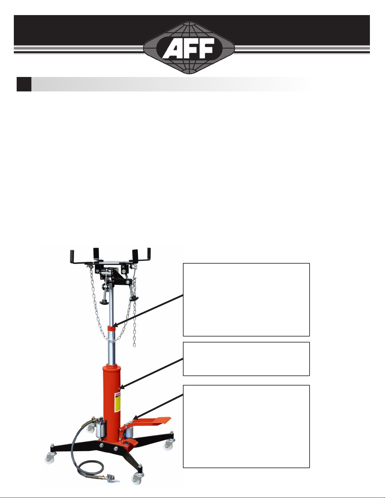
Air Purging Instructions
If the jack does not raise the load or raises very slowly after activating the pump pedal there may be air
trapped in the primary ram and hydraulic system.
Step 1
Loosen bleeder screw
counterclockwise
Step 2
Take off the M6x30 bolt. Loosen
M6x5 screw by half turn with 3mm
allen wrench. Operate the foot
pedal 2-3 times until oil escapes
from hole without air bubbles.
Keep pedal depressed and tighten
both screw and bolt.
Step 3
Operate the foot pedal and lift the
adapter to the max height. Loosen
screw (#16.) Operate the foot
pedal 4-5 times to eliminate any
existing air in piston. Tighten
screw.
Page 3

Page 4
OPERATING INSTRUCTIONS
1. Lift the vehicle to the desired work height and support the vehicle in accordance with the lift
manufacturer’s recommended support procedure and all the instructions and warnings in this manual.
2. Use an under hoist stand rated greater than the weight of the engine to support the engine before
unbolting the transmission from the engine or bolting the transmission to the engine.
3. Position the transmission jack directly under the transmission. The transmission jack’s saddle (48)
can be raised either by foot pump operation (35) or depressing the air valve. A minimum of 100 PSI of
compressed air is necessary to lift 1,100 lbs by way of air valve.
4. Raise the jack’s saddle to a height very close to the center of balance of the transmission but do not
come in contact with the transmission. The saddle has 4 arms that are in an “L” shape. The arms can
be used on the short or long portions of the “L.” Loosen the bolts to telescope the arms out as far as
needed to cradle the transmission. Once adjusted tighten the bolts using the wing nuts provided. Using
the foot pump pedal slowly pump the pedal until the saddle supports the transmission. Sometimes it is
necessary to turn the fore and aft adjustment handle and/or the side to side adjustment handle so the
saddle is in proper alignment with the transmission.
5. Make sure the safety chain is very tight when securing the transmission to the saddle and before
removing the under hoist stand that has been supporting the engine.
6. IMPORTANT: There are two methods for lowering the jack’s saddle. The foot release (32) should only
be depressed to lower the saddle quickly without any weight on the saddle. Fine and slow control of
lowering the load should be done with turning the release valve handle in a counterclockwise rotation.
The more the handle is rotated in a counterclockwise rotation the faster the loaded saddle will descend.
7. Once the transmission has been removed from the engine very slowly turn the release handle in a
counterclockwise rotation.
8. When installing a transmission follow the above instructions but in the applicable order and according to
the manufacturer’s installation procedures.
PREVENTATIVE MAINTENANCE
1. When not in use store the jack in a dry location with the saddle in the lowest position.
2. Always store the jack in a well protected area where it will not be exposed to inclement weather,
corrosive vapors, or any other harmful elements. The jack must be removed of water, snow, sand, grit,
oil, grease, or other foreign matter before using.
3. Lubricate moving parts excluding the telescopic rams monthly with a general purpose grease.
4. To keep the labels clean and readable use a mild soap solution.
5. To ensure best performance and longer equipment life it is recommended to replace the hydraulic oil
once per year. With jack in the lowest position remove the air vent screw (25) and lay the jack on its
side. Drain the oil into a suitable container making sure no dirt or debris gets into the system. Set the
jack in its upright position and fill with approved hydraulic jack oil. Replace the air vent screw (25) and
purge away air from hydraulic system as described in the ASSEMBLY section.
6. Do not attempt to make any hydraulic repairs unless you are a qualified hydraulic repair technician that
is familiar with this equipment. Repairs must be done by an authorized repair center.
7. IMPORTANT: To prevent seal damage and jack failure never use alcohol, hydraulic brake fluid, or
transmission oil in the jack. Use hydraulic oil only.

Page 5
TROUBLESHOOTING
PROBLEM POSSIBLECAUSE SOLUTION

Page 6
JACK DIAGRAM
Page 7
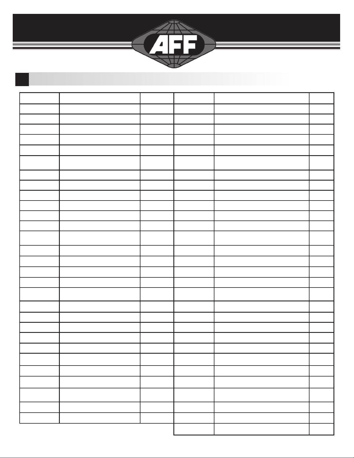
JACK PARTS LIST
Parts No. Description Qty Parts No. Description Qty
1Dust ring 130 Pump 1
2O-ring 131 U-limited 1
3U-ring 132 Lock washer 1
4Oil cup 133 Screw 1
5Caster 234 Release pedal 1
6Second piston rod 135 Pin 1
7Retainer ring 136 Cotter pin 1
8Dust ring 137 Washer 2
9O-ring 138 Foot pedal 1
10 U-ring 139 Retainer ring 4
11 Round nut 140 Connect rod 2
12 O-ring 141 Pin 2
13 First piston rod 142 Pin 1
14 Limited ring 143 Legs 2
15 Plunger 144 Nut 4
16 Screw 145 Lock washer 4
17 Steel 146 Washer 4
18 O-ring 147 Caster with brake 2
19 Round nut base 148 Washer 4
20 Waher 2 49 Lock washer 4
21 Oil tank 150 Bolt 4
22 Pin 151 Saddle 1
23 Cotter pin 352 Screw 2
24 Handle 1 53 Air hose connector 1
25 Handle cover 1 54 Air valve 1
26 Exhaust screw 155 Air hose 1
27 Seal ring 156 Second Limited valve 1
28 Ram 157 Washer 1
29 Washer 1 58 Spring 1
59
Steel ball 1
Page 8
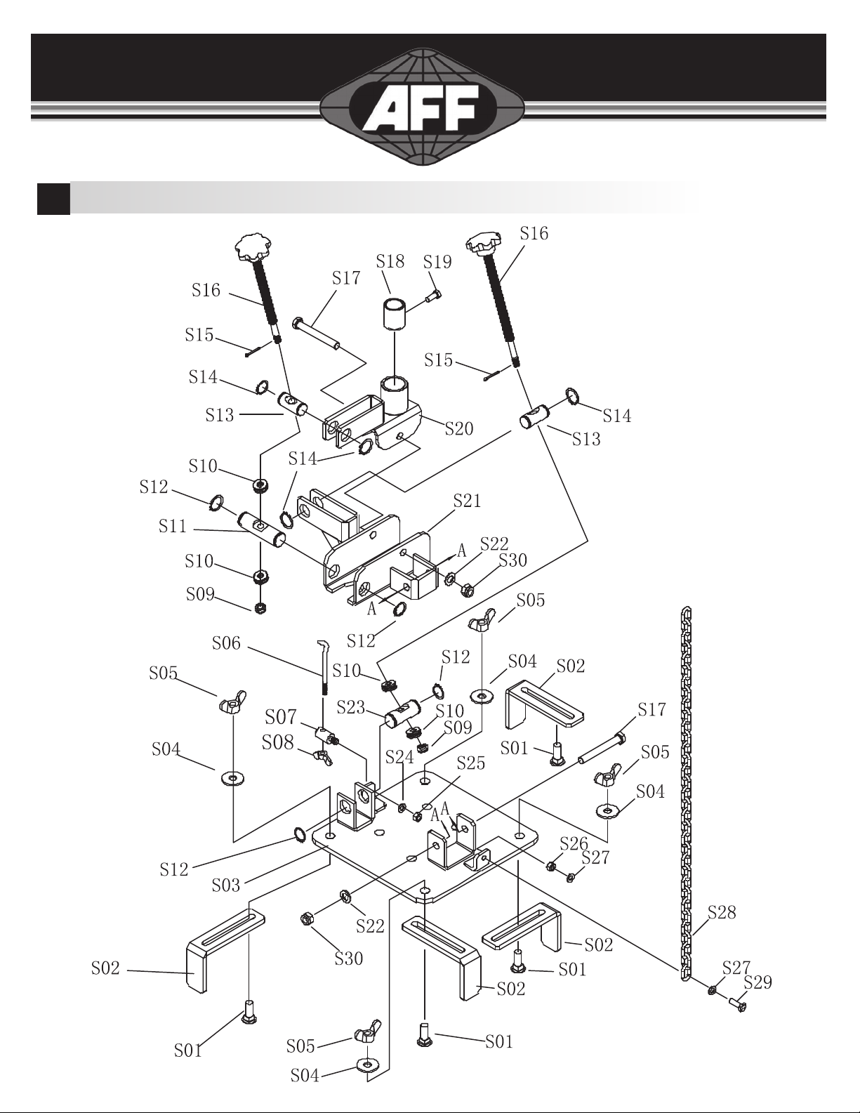
SADDLE DIAGRAM

Page 9
SADDLE PARTS LIST
Parts No. Description Qty Parts No. Description Qty
S01 Bolt 4S16 Adjusted Handle 2
S02 Block 4S17 Bolt 2
S03 Plate 1S18 Cover 1
S04 Washer 4S19 Bolt 1
S05 Nut 4S20 Saddle Base 1
S06 Chain Hook 1S21 Plate Carrier 1
S07 Hook Base 1S22 Washer 2
S08 Nut 1S23 Pin2 1
S09 Nut 2S24 Washer 1
S10 Bear 4S25 Nut 1
S11 Pin 1S26 Nut 1
S12 Retainer Ring 4S27 Washer 2
S13 Pin1 2S28 Chain 1
S14 Retainer Ring 4S29 Bolt 1
S15 Cotter Pin 2S30 Nut 2

Page 10
PUMP DIAGRAM
Page 11
PUMP PARTS LIST
PARTS No. DESC QTY PARTS No. DESC
P1 Screw 1 P25 Screw
P2 Steel Ball 1 P26 Steel Ball
P3 Nut 1 P27 Steel Ball Base
P4 O-Ring 1 P28 Spring
P5 Pin Cover 1P29 Screw
P6 Dust Cover 1 P30 Spring
P7 Dust Plunger 1 P31 Washer
P8 Big Pump Core 1 P32 Screw
P9 O-Ring 1 P33 Spring
P10 Washer 1P34 Spring
P11 Spring 1P35 O-Ring
P12 Small Pump Core 1P36 Push Rod
P13 Washer 1P37 Copper Washer
P14 O-Ring 1 P38 Screw
P15 U-Ring 1 P39 Screw
P16 Pump Core Base 1 P40 Screw
P17 Retainer Ring 1 P41 Connector
P18 O-Ring 1 P42 Filter
P19 Small Copper Washer 1P43 First Limited Valve
P20 Steel Ball 7 P44 Pump
P21 Release Valve Core 1 P45 Steel Ball
P22 O-Ring 3 P46 Spring
P23 Spring 1P47 Copper Washer
P24 Steel Ball 1 P48 Air Motor

Page 12
WARRANTY INFORMATION
1 YEAR LIMITED WARRANTY
SureWerx USA Inc. warrants, to the final purchaser, jacks and related service equipment
distributed by it to be free from defects in material and workmanship for a period of 1 year from
date of sale. This warranty covers SureWerx USA Inc. and Viking branded products.
If a jack or related equipment is determined to be defective during the warranty period, it will
be repaired or replaced without charge provided that the equipment is shipped, transportation
charges prepaid and with proof of purchase to SureWerx USA Inc. or to a designated field service
depot.
This warranty does not apply to parts damaged from accident, overload, or abuse, nor does
it apply to product which has been altered or used with special attachments other than
recommended by the distributor or equivalent.
THERE ARE NO OTHER WARRANTIES OF ANY SORT, EXPRESS OR IMPLIED, AND SELLER
SPECIFICALLY DISCLAIMS ANY WARRANTY OF MERCHANTABILITY OR OF FITNESS FOR ANY
PARTICULAR PURPOSE. THE SELLER’S SOLE OBLIGATION, WHICH SHALL REPRESENT THE
BUYER’S SOLE EXCLUSIVE REMEDY, SHALL BE TO REPAIR OR AT THE SELLER’S OPTION TO
REPLACE ANY PRODUCT OR PART DETERMINED TO BE DEFECTIVE AS AFOREMENTIONED. IN
NO EVENT SHALL THE SELLER BE LIABLE FOR ANY SPECIAL, DIRECT, INDIRECT, INCIDENTAL,
CONSEQUENTIAL, OR OTHER DAMAGES OF A SIMILAR PRODUCTION TIME, OR LOSS OR
EXPENSES OF ANY NATURE, INCURRED BY THE BUYER OR ANY THIRD PARTY.
For warranty information call SureWerx USA toll free at 800.323.7402
Table of contents
Other AFF Jack manuals


Popular Jack manuals by other brands

Hi-Force
Hi-Force JSS 1144 Operating and maintenance instructions

Silverline
Silverline Scissor Jack 1 Tonne quick start guide

KRAFTWERK
KRAFTWERK 38106 operating instructions

Porto-Power
Porto-Power B65041 Operating instructions & parts manual

Cornwell Tools
Cornwell Tools CSEVS22T operating manual

Daytona
Daytona DJS3TBK Owner's manual & safety instructions


