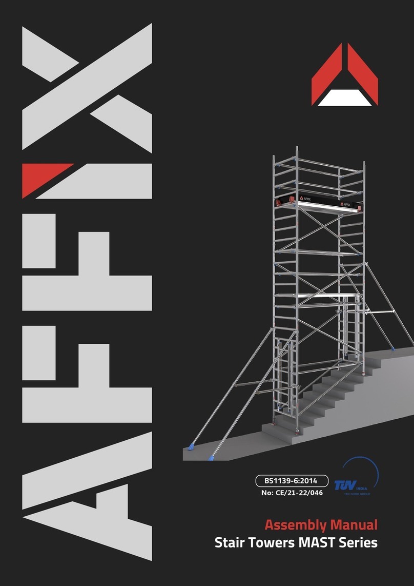
AFFIX MALT Series User manual

Assembly Manual
Linked Towers MALT Series
BS1139-6:2014
No: CE/21-22/046

01
Aluminium LInked Towers
MALT
The AFFIX Linked Tower is a mobile access tower manufactured in our
ISO 9001 accredited facility.
The AFFIX Linked Tower is a mobile access tower manufactured in our
ISO 9001 accredited facility.
This user guide provides you with step by step instructions to ensure your
system is assembled easily and safely, using the 3T (Through the Trapdoor)
method.
This user guide provides you with step by step instructions to ensure your
system is assembled easily and safely, using the 3T (Through the Trapdoor)
method.
BS1139-6 3 7/9 XXXD

WARNING
NEVER FORGET TO TIE
THE STRUCTURE
DESCRIPTION:
Through The Trapdoor (3T) Method:
The 3T method of construction is an approved method of assembly and it minimizes the risk of
a fall from height. The erector can complete an ‘assembly or access’ platform level from which
the ‘next lift’ of frames, braces and platform is added, until the final working height of the tower
is achieved. By following the 3T method, the erector sits through the hatch of the platform with
their feet resting on the frame rungs. In this position the erector can attach the guardrail braces.
Once guard-rails are secured in position the erector can climb onto the platform and continue
constructing the next level.
Compliances:
The Affix MALT Linked Tower structure has been tested and certified to BS1139-6: 2014 by TUV,
India
The Affix MALT Series Aluminium Linked Tower offers customer the flexibility to work on the
long span platform of 7.5 Mtrs Length together by joining two Double Width Towers together
through and additional platform at multiple levels. The MALT Series towers allow the user to
work on longer platform with more workers to work simultaneously. This tower is ideal for use
when work is required to be at multiple levels simultaneously.
The information and instructions included in this manual are provided to help get the best
possible service from your MALT Series Aluminium Linked Tower. This user guide provides you
with step by step instructions to ensure your system is assembled easily and safely, using the
3T (Through the Trapdoor) method.
02

Maximum Safe Working Loads
The safe working load of the tower is 1250 kgs including its own weight.
The maximum safe working load of any individual platform is 250 kgs
evenly distributed.
If the tower is to be used for any specific loading contact
your supplier or the manufacturer, Affix Scaffolding WLL.
RECOMMENDATIONS :
Recommend a minimum of two people to assemble, dismantle and move the platform tower.
Check that all components are on site and in good working order.
Towers must always be climbed from the inside of the assembly using the ladder.
Lifting of components must be done inside the effective base area of the tower.
Damaged components or components from other tower systems must never be used.
Never build linked towers without correctly adopting the suggested stability solution.
Outdoor or Indoor towers must be secured to a building or fixed structure.
Linked towers must never be built as free-standing structures. Suitable tying-in must be used.
Do Not use boxes or steps to gain additional height.
Do Not lift or suspend an assembled mobile tower.
Beware of horizontal loads which can lead to instability of the tower. The Max. side force is 20kg.
Ensure that the assembly location is checked to prevent hazards during assembly or moving
and while working on the tower. Particular attention should be given to the ground condition,
whether level or sloping, obstructions and wind conditions. The ground condition must be
capable of supporting the tower structure.
03USAGE ADVICE
Aluminium Linked Towers

Safety Checklist :Safety Checklist :
Air speed and resultant action to be taken
Mobile towers - 3T Method Checklist
Beufort Scale
01 mph
12 mph
17 mph
25 mph
40 mph
Calm, smoke rises easily upwards No action needed
Cease work
No action needed, keep a watch
If expected, dismantle the tower
If expected, tie tower to a rigid
structure
Moderate breeze, raises dust
Gale force, cannot even walk
Raises loose papers, leaves and small
twigs move
Strong breeze, tree branches bend, unable
to use umbrella
3
4
5
6
Description Air Speed Action to be taken
Ensure all brace claws operate and lock correctly prior to erection
Inspect components prior to use
Tower upright and level
Tower properly tied in to a fixed structure
Diagonal braces fitted
Platforms located and wind-locks on
Toe boards located
Check that the guardrails are fitted correctly
04USAGE ADVICE

WARNING
NEVER STAND ON AN
UNGUARDED PLATFORM
Safe working load on the working platform is 250kgs evenly distributed.
ASSEMBLY PROCESS :
PREPARATIONPREPARATION
Locate the tower, ensuring ground is level.
Check the locking triggers in the bracing hooks such that they are working properly.
Make ready the tying in option.
Sort the braces into horizontal and diagonal braces, the diagonals are slightly longer.
Also note that the braces are differently color coded.
The load on the tower should not exceed 1250 kgs.
The maximum recommended platform height is 9M.
SAFE WORKING LOADS AND HEIGHTS
05
Aluminium Linked Towers

FIRST LEVEL
Insert the Base Jack with the jack
pipe inside the bottom of the tubes
of the 1st level 2 Rung Ladder Frame
and 2 Rung Span Frame.
DO NOT USE Hammer.DO NOT USE Hammer.
Step 1
06ASSEMBLY
Step 2.2Step 2.2
One person should hold the frame in
upright position during this step.
Hook both the bottom 2 Horizontal Braces
horizontally to both the Span frame's vertical
pipes, just above the 1st rung.
Step 2.1Step 2.1
Step 2

SECOND LEVEL
Step 3
Level the structure using a Spirit Level on
the Rungs and the braces.
If adjustment required, adjust using the
adjustable jack.
Step 3.1Step 3.1
Step 4
Step 4.1Step 4.1
07ASSEMBLY
Insert the 2nd level Walk-through Frame
and Ladder Frame into the corresponding
spigots of 1st level Span Frame and
Ladder Frame. For clamping instructions
refer to the Clamping Instructions section
on Page 20.

Step 6
Step 5
Step 5.1Step 5.1
Hook the Diagonal Brace to the 3rd Rung
of the 2nd level Walk-through Frame at
one end and the other end should be hooked
to the 1st Rung of the 2nd level Ladder
Frame on the other side.
Step 5.2Step 5.2
Hook the 2nd Diagonal Brace to the 1st
Rung of the 2nd level Walk-through Frame
at one end and the other end should be
hooked to the 3rd Rung of the 2nd level
Ladder Frame on the other side.
08ASSEMBLY
Hook the Diagonal Brace to the 1st Rung
of the 1st level Span frame at one end and
the other end should be hooked to the 1st
Rung of the 2nd level Ladder frame.
Hook the 2nd Diagonal Brace to the 1st
Rung of the 2nd level Ladder frame at
one end and the other end should be
hooked to the 1st Rung of the 1st level
Span frame.
Step 6.1Step 6.1
Step 6.2Step 6.2

Hook the Intermediate trapdoor platform
on the 2nd Rung of the 2nd level frames.
Make sure the trapdoor is towards the
ladder side.
Step 7
Step 8.1Step 8.1
Hook the lower pair of Horizontal Braces
to the 3rd Rung of both the 2nd level
frames.
Step 8.2Step 8.2
Hook the upper pair of Horizontal Braces
to the 4th Rung of both the 2nd level
frames.
Using the 3T method, standing on the
ladder and leaning back against the edge
of the trapdoor aperture, fit the horizontal
braces as mid rails and guardrails.
Step 8
09ASSEMBLY
Step 7.1Step 7.1
Also hook the Intermediate fixed platform
on the 2nd Rung of the 2nd level frames
beside the trapdoor platform .
Step 7.2Step 7.2

THIRD LEVEL
Step 9
Insert the 3rd level Walk-through Frame
and Ladder Frame into the corresponding
spigots of 2nd level Walk-through Frame
and Ladder Frame. For clamping instructions
refer to the Clamping Instructions section
on Page 20.
Step 10
Step 10.1Step 10.1
Hook the Diagonal Brace to the 3rd Rung
of the 2nd level Walk-through Frame at
one end and the other end should be
hooked to the 1st Rung of the 3rd level
Ladder Frame on the other side.
Step 10.2Step 10.2
Hook the 2nd Diagonal Brace to the 1st
Rung of the 3rd level Walk-through Frame
at one end and the other end should be
hooked to the 3rd Rung of the 2nd level
Ladder Frame on the other side.
10ASSEMBLY

Step 12
Hook the working Fixed Platform on the
2nd Rung of the 3rd level frames. Make sure
the platform is not on the ladder side.
Step 11
Step 11.1Step 11.1
Hook the Diagonal Brace to the 3rd Rung
of the 3rd level Walk-through Frame at
one end and the other end should be
hooked to the 1st Rung of the 3rd level
Ladder Frame on the other side.
Step 11.2Step 11.2
Hook the 2nd Diagonal Brace to the 1st
Rung of the 3rd level Walk-through
Frame at one end and the other end
should be hooked to the 3rd Rung of the
3rd level Ladder Frame on the other side.
11ASSEMBLY
Hook the working Trapdoor Platform on
the 2nd Rung of the 3rd level frames
beside the Fixed Platform. Make sure the
trapdoor is towards the ladder side.
Step 12.1Step 12.1
Step 12.2Step 12.2

Step 13
Step 14
One Tower assembly is now complete
12ASSEMBLY
Step 13.1Step 13.1
Hook the lower pair of Horizontal Braces
to the 3rd Rung of both the frames of 3rd
level on both the sides.
Using the 3T method, standing on the
ladder and leaning back against the edge
of the trapdoor aperture, fit the horizontal
braces as mid rails and guardrails.
Step 13.2Step 13.2
Hook upper pair of Horizontal Braces to
the 4th Rung of both the frames of 3rd
level on both the sides.

Step 16
Hook the lower set of 2 brdige decks (fixed
platforms) to the 2nd rung of the 2nd level
frames on either side
Step 15
Start erecting another tower at a distance
of 2.5 Mtrs from the first tower. Ensure
the Walkthrough Frames of both the
towers face each other.
Repeat Steps 1 to 8 and prepare the other
tower upto the intermediate platform level.
13ASSEMBLY

Step 17
It is safe to remove the safety gates
now from both the sides.
Step 18
Step 18.1Step 18.1
14ASSEMBLY
Hook the lower pair of Horizontal Braces
to the 3rd Rung of both the Walkthrough
frames of both the towers, as Mid rail.
Step 17.1Step 17.1
Hook the upper pair of Horizontal Braces
to the 4th Rung of both the Walkthrough
frames of both the towers, as Guard rail.
Step 17.2Step 17.2

Step 19
Step 20
15ASSEMBLY
Insert the 3rd level Walk-through Frame
and Ladder Frame into the corresponding
spigots of 2nd level Walk-through Frame
and Ladder Frame. For clamping instructions
refer to the Clamping Instructions section
on Page 20.
Step 20.1Step 20.1
Hook the Diagonal Brace to the 3rd Rung
of the 2nd level Walk-through Frame at
one end and the other end should be
hooked to the 1st Rung of the 3rd level
Ladder Frame on the other side.
Step 20.2Step 20.2
Hook the 2nd Diagonal Brace to the 1st
Rung of the 3rd level Walk-through Frame
at one end and the other end should be
hooked to the 3rd Rung of the 2nd level
Ladder Frame on the other side.

Step 21
Step 22
16ASSEMBLY
Step 21.1Step 21.1
Hook the Diagonal Brace to the 3rd Rung
of the 3rd level Walk-through Frame at
one end and the other end should be
hooked to the 1st Rung of the 3rd level
Ladder Frame on the other side.
Step 21.2Step 21.2
Hook the 2nd Diagonal Brace to the 1st
Rung of the 3rd level Walk-through
Frame at one end and the other end
should be hooked to the 3rd Rung of the
3rd level Ladder Frame on the other side.
Hook the working Fixed Platform on the
2nd Rung of the 3rd level frames. Make sure
the platform is not on the ladder side.
Hook the working Trapdoor Platform on
the 2nd Rung of the 3rd level frames
beside the Fixed Platform. Make sure the
trapdoor is towards the ladder side.
Step 22.1Step 22.1
Step 22.2Step 22.2

Step 23
Step 24
17ASSEMBLY
Step 23.1Step 23.1
Hook the lower pair of Horizontal Braces
to the 3rd Rung of both the frames of 3rd
level on both the sides.
Using the 3T method, standing on the
ladder and leaning back against the edge
of the trapdoor aperture, fit the horizontal
braces as mid rails and guardrails.
Step 23.2Step 23.2
Hook upper pair of Horizontal Braces to
the 4th Rung of both the frames of 3rd
level on both the sides.
Hook the upper set of 2 brdige decks (fixed
platforms) to the 2nd rung of the 3rd level
frames on either side

Step 25
Step 26
18ASSEMBLY
Hook the lower pair of Horizontal Braces
to the 3rd Rung of both the Walkthrough
frames of both the towers, as Mid rail.
Step 25.1Step 25.1
Hook the upper pair of Horizontal Braces
to the 4th Rung of both the Walkthrough
frames of both the towers, as Guard rail.
Step 25.2Step 25.2
Remove the temporary safety gate from
both the Walkthrough frames.

Step 27
19ASSEMBLY
Insert the wooden toe-boards in the
toe-board holder slot on all the sides and
insert the wooden toe-board
Step 28
Last, but not the least, follow the tying-in methodology
and instructions provided on page 23 and tie the tower
to a fixed rigid structure before start using it.
Table of contents
Other AFFIX Ladder manuals
Popular Ladder manuals by other brands
KRAUSE
KRAUSE 835239 Assembly and user's manual
Rivers Edge
Rivers Edge CLASSIC XT Operator's manual
Little Giant
Little Giant SafeFrame Instructions for use

Little Giant
Little Giant Classic User instructions

Calspas
Calspas Cal Designs Deluxe Spa Step WOOD118-KD Assembly

Little Giant
Little Giant LOOT BOX quick start guide

