AFFORDABLE LIFTS KCSPM3648 Setup guide

Assembly And Installation Manual For
Affordable Lift Model KCSPM3648
Specifically For Serial Number E9997
Manual Print Date: Dec 01, 2023, 01:03 PM EST
Lift E9997 Specifications:
Station Height:
38.0"
Weight Capacity:
500 lbs
Column Length:
78.0"
Color:
Gloss Black
Motor:
1500 lbs w/ Tethered Controller
Base:
Armed Base
Safety System:
Self Retracting Lifeline (SRL)
Column Bracing:
None/NA
Wheel Kit:
Yes
Rain Guard:
Yes
Battery Backup:
Not Purchased
Shipped As:
Assembled
Shipped On:
On A Regular Pallet
All images in this manual are representational only.

Table of Contents
Click on a Section to jump to that section.
Section
Section Number
Introduction
Section 1
Safety
Section 2
Warnings
Section 3
Ter mi no lo gy
Section 4
Prepare to Assemble and Install Your Lift
Section 5
The Wheel Kit
Section 6
Unpack Your Lift
Section 7
Position Your Lift
Section 8
Electrical Power
Section 9
Test Your Lift
Section 10
Adjust Your Lift’s Maximum Height
Section 11
Anchoring The Armed Base
Section 12
Finalize Column Bracing
Section 13
Platform Gates
Section 14
Minimize Platform “Twist”
Section 15
Controller Storage Box
Section 16
The Transition Ramp
Section 17
Battery Backup
Section 18
Canopy Frame
Section 19
Maintenance
Section 20
Troubleshooting
Section 21

1. Introduction
Congratulations on your purchase of a new platform lift! We sincerely hope that this lift will help you accomplish the things that
are important to you and those you love.
Note:
We have many of the assembly steps recorded on video for your reference. These videos are not a substitute for this
manual. They should be used alongside this manual. To find the videos use the video links throughout this manual or
Click
Here
.
Note:
The photos in this guide display lifts in various stages of installation. It is often the case that some recommended safety
feature is not yet in place in a specific photo. In particular, an anti-pinch point wall and a basic stair handrail are missing in
some of the scenarios we photographed.
Note:
There are some minor design changes between different lifts pictured here. These photos might not exactly match your
particular lift.
Note:
If your lift was shipped with some bolts and fasteners already in place and you find it necessary to temporarily remove
them, they must be re-inserted in the same direction. Inserting the bolt in the opposite direction may cause problems.
Note:
Throughout this document this is used as a caution symbol:
Please abide by all safety precautions so that you can
safely enjoy your lift and all that it has to offer.

2. Safety
2.1.
Safety is paramount!
If you have a question or concern about the safe installation or operation of your lift please call
Customer Support at (USA) 434-515-2321 (Provide your Serial Number 'E9997' and contact information when you call).
2.2.
DO NOT USE YOUR LIFT OR ALLOW OTHERS TO USE YOUR LIFT IF YOU SUSPECT IT MAY BE IN AN
UNSAFE CONDITION
2.3. Warning:
No one should ride the lift until the Safety Backup System is installed and all lift testing is complete.
2.4.
Use common sense when installing or operating this equipment. Please read all the instructions before beginning
assembly and installation.
2.5.
The installer and operator are responsible for the safe operation of this equipment.
It is your responsibility to ensure
and verify that this equipment is safely installed. It is your responsibility to ensure and verify that inspections and
maintenance is done.
It is your responsibility to know and comply with all applicable legal codes and regulations regarding
your platform lift.
2.6.
Be sure to lift heavy objects using your legs, not your back.
2.7.
Do not allow children or people who are not able to understand the safe operation of the lift to use or play with the
controllers. Letting unqualified people operate the lift without supervision puts them and anyone around the lift at severe
risk. Allow only capable persons to operate the lift.
2.8.
"Pinch Point" risk is inherent in any mechanical device of this nature. This is the risk of something (such as a toe) getting
caught underneath something as the Platform ascends.
Inadequate vigilance and safety in pinch point risk areas can
cause injury or death or can harm your lift.
A common and prominent pinch point risk area is any gap underneath a
landing, such as a porch or deck. We recommend that you identify any such areas in and around your lift and take safety
precautions. Eliminate pinch point risk by covering openings below the landing with a vertical or angled plywood wall to
prevent body parts and items from being trapped between a landing or floor and the Platform as the lift ascends upwards
from the ground.
Below are two "shear points" before and after installing two different types of shear protection:
Misuse of this equipment can cause serious injury or even death

3. Warnings
Caution! Carefully read the owners manual and the following warnings prior
to use. Failure to comply with the following may result in serious bodily
injury, death, or damage to the lift. If you have questions, contact Customer
Support at (USA) 434-515-2321 (Provide your Serial Number 'E9997' and
contact information when you call).
!"
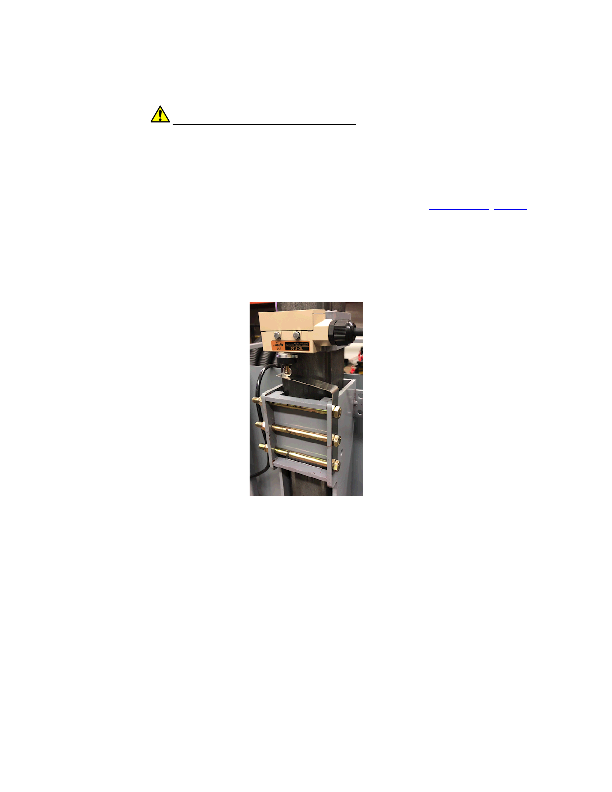
Prior to use, ensure that the safety mechanism is in place properly. Never use a lift without a safety mechanism properly
installed and functional!
!"
Prior to each use, inspect the cable and components for signs of fraying or damage.
!"
Always lock gates prior to use. Never operate the lift with any gates unsecured.
!"
Always lock/secure wheelchair or cargo from shifting while in use.
!"
This lift is to be used exclusively for the transport of cargo or a wheelchair and occupant and an additional adult where
assistance is required.
!"
Improper use of lift may result in personal injury or damage to the lift. All users must read and follow operating
instructions prior to use of lift.
!"
Ensure that the lift is properly installed and is stable prior to use of the lift. Failure to ensure proper installation may result
in an increased risk that the lift will tip over or otherwise malfunction, resulting in damage to the lift and/or personal injury.
!"
Do not exceed the maximum load capacity.
!"
Remain in the correct, upright position while the lift is in use. Keep entire body within the lift at all times. Failure to
remain in position may result in pinch or crush hazards at the deck/flooring platform and property damage or personal
injury from a malfunction of the lift or falling from the lift.
!"
If the lift is installed to go through an opening to another level, it is particularly important to never rest arms, feet or limbs
on handrails or extending from the lift. Narrow openings pose a substantial risk of injury to the lift or serious personal
injury.
!"
Prior to use, ensure that electrical power is installed on a grounded electrical circuit.
!"
Prior to use, inspect for proper function, required maintenance, or damage. If a problem exists, cease use of the lift
immediately. Do not attempt to make repairs or alterations to the lift. Contact a licensed professional or customer support
for any necessary repairs.
!"
Do not conduct any maintenance, repairs, or otherwise work on this lift while it is operational or plugged in unless
instructed to do so by customer support.
!"
Do not alter or modify this lift or any of its safety devices in any way.
!"
Do not expose any electronic part of this lift to liquid or harsh weather conditions.
!"
Do not use if snow, ice, or other debris have accumulated on the lift.
!"
Do not operate this lift in the presence of combustible or explosive gas or fumes.
!"
Completely disconnect the lift from its power source prior to cleaning the lift.
!"
Do not operate this lift if you are under the age of eighteen (18) years old. All users of this lift who are under the age of
eighteen (18) years old must be accompanied by an adult who is authorized to use this lift and has read its operating
instructions.
!"
Keep children away from this lift at all times unless using this lift while accompanied by an authorized adult who has
read its operating instructions.
!"
Do not stand or place any body part under the lift platform at any time.
!"
When using the lift, ensure that no persons, pets or objects are in the upward or downward path of the lift platform or
collar.
!"
Keep all loose articles, hair, and other objects away from the moving portions of the lift at all times.
!"
Keep hands and feet away from moving parts while the lift is operational
!"
Do not store any items or objects on or under the lift platform.
!"
Store lift in a temperature controlled, dry environment when not installed for use.
!"
Ensure that the lift platform is fully in the down position and all electrical components are disconnected from power prior
to moving the lift.
!"
Use appropriate lifting/transport precautions when moving the lift. The lift is very heavy.
!"
Keep lift controllers in a secure location out of reach of children.
!"
Remain aware of your surroundings and ensure you are able to hear well at all times while the lift is in use
FAILURE TO COMPLY WITH ANY OF THE ABOVE WARNINGS MAY RESULT IN
SERIOUS BODILY INJURY, DEATH, CRUSH, ELECTRICAL, TRIPPING
HAZARDS OR DAMAGE TO THE LIFT.

4. Terminology
4.1.
Front, Back, Right and Left Sides:
The Column is located on the back side of the lift. The side of the lift opposite the
back side is the front side. Right and left are determined when you face the lift's Platform from the front.
4.2.
Please look over the sample photo below to familiarize yourself with the important parts of your Affordable Lift.
Below are the names and images of lift parts and components that were
shipped to you:
Row
Part Number
Item
Description
Qty
Sample Image
1
Welcome Letter
Welcome Letter and
Instructions
1
None
2
Packing List
List of all parts and
components shipped
1
None
3
Assembly and Installation
Manual for the KCSPM3648
Also available via email on
request - call (USA)
434-515-2321 (Provide your
Serial Number 'E9997' and
contact information when you
call)
1
None

4
Affordable Lift -
Preassembled
42.0"x52.0"x88.8", Gloss
Black
1
5
Spray Paint Can
Rustoleum Protective Enamel,
Gloss Black, 12 oz
1
6
3500009
Wheel Kit - Standard
Wheels
8"x2.5"
2
7
MW82.5x 0.625xX
Wheel Kit - Bolts
5/8"-11x4"
2
8
6000111
A16B33C2.75
Left Side Ramp
A16"xB33"xC2.75", Gloss
Black
1
5. Prepare to Assemble and Install Your Lift
5.1. We Are Here To Help:
We would much rather have you call us for help than have you install your lift incorrectly. Your
lift's serial number is
E9997
. If you have questions or problems during assembly please call Customer Support at (USA)
434-515-2321 (Provide your Serial Number 'E9997' and contact information when you call).
5.2. Receiving Your Lift:
If damage has occurred during shipping immediately document it with photographs and notify our
Shipping Department at (USA) 434-207-8444 (Provide your Serial Number 'E9997' and contact information when you call).
Check your lift for damage before signing the papers with the delivery man, when applicable. If there is damage, note it on
the delivery paperwork appropriately and notify Affordable Lifts.
If damage is found after the delivery papers are signed,
we will not be able to file a claim for the damage with the shipping company on your behalf.
5.3.
We recommend that at least two adults work together to install this lift. Some parts of your lift are quite heavy and having
two or more people assemble your lift reduces the risk of injury. Affordable Lifts is not responsible for injuries that occur
while installing or utilizing your lift.
5.4.
Most customers prefer their lift be oriented for straight-through travel. This means entering one side of the lift (right or left)
going up and then continuing out the other side (right or left). Sometimes this is not practical. If you are using a wheelchair
or walker, remember to allow adequate space to navigate onto and off of your lift's Platform.
5.5.
We recommend that if possible, the Column side of the lift be installed closest to a nearby wall. If bracing is desired, then
this positioning will make bracing easier.
5.6. Before you begin:
!"
The installation site should be flat and level, or you should be prepared to use steel or plastic shims to level
your lift.
!"
The installation site should be clear of debris and as accessible as possible.
!"
Your lift weighs approximately 450 lbs and it has a Platform weight capacity of 500 lbs. Be sure that the floor of your
installation location can support this combined weight.
!"
The lift should sit on a solid surface (concrete, asphalt, solid flooring, etc) or substantial pavers. Anchoring on asphalt
installation requires inserting steel anchors into an epoxied hole.
!"
Pinch point protection should already be installed.
!"
If you remove a section of a landing railing then, if the landing is high enough you should install a safety gate in its place.
!"
Children and pets should be excluded from the area during installation.

6. The Wheel Kit
6.1.
Your lift was shipped with a detachable Wheel Kit. We will discuss the Wheel Kit now because you may choose to use it
in the next steps.
The Wheel Kit consists of two 8" wheels and their axle bolts. These wheels allow the lift to be tilted backwards and wheeled
over a smooth hard surface.
Here is a photo of the Wheel Kit after installation:
While this is an easy way to move the lift, it is still a two person operation.
These wheels should always be removed prior to actually using the lift.
6.2. Wheel Kit Installation or Removal:
1.
Locate the wheel mounting points on the back of the Base. Use a pry bar to lift the corner of the base up about 1".
2.
Place the bolt through the wheel as shown in the photo above.
3.
Use a wrench to secure the wheel by tightening the bolt.
4.
Reverse this process when removing the Wheel Kit.
6.3. Using The Wheel Kit:
1.
With one person at the back of the lift and one person at the front, tilt the lift backwards so that it is balanced on its
wheels.
2.
Carefully move the lift along a flat, hard surface to its desired position.
3.
Remove and store the Wheel Kit once the lift is in place.
7. Unpack Your Lift
7.1. Keep in Mind:
As you unpack,
watch out for any shipping damage
. If you sign for a damaged lift without noting
shipping damage you will not be able to make a claim later.
7.2. Small Parts:
Look inside the grey Controller Storage Box to see what small parts and paperwork it contains.
7.3. Zip Ties:
Remove any zip ties that secure cables or rope to the Column. Do not remove any other zip ties at this point.
7.4. Unbolt the Platform:
The Platform has long bolts through its floor holding it to the pallet. Use a wrench to unbolt and
remove them. If there are additional screws through anchor holes in the Armed Base, remove them as well. Slide the lift
from the pallet.
7.5. Wheel Kit option:
You have an attachable Wheel Kit that is useful for moving the lift across a flat, hard surface.
Attaching the wheels will let you tilt the lift back as if it were on a dolly. If this would help you move your lift, consider
attaching the wheels now. See the
Wheel Kit Section
for wheel attachment instructions.

7.6. Move to installation site:
Move the lift and its parts to the lift installation site.
7.7. Weather:
Electrical components should be protected from weather until properly installed.
8. Position Your Lift
8.1.
Move and orient the lift to the position where it will be used. Do NOT anchor it at this time.
8.2.
If your Wheel Kit is installed, remove and store the wheels now.
Do NOT use the lift while the wheels are attached.
8.3.
The back of the Column should be at least 3" from any vertical plane of a wall or obstruction so that the Collar can move
freely. Note that walls are often not truly vertical! The Platform, the Collar and everything attached to them must have
enough clearance to go up and down their travel height without hitting any obstructions.
8.4.
Use steel or plastic shims (not included) to make the Column plumb.
8.5.
The edge of the Platform, when at the station height, should come to approximately 0.5" (1/2") of the edge of the landing.
Note that many landing edges are not actually square or level.
Below is a typical assembled freestanding lift, positioned for use and with a ground transition ramp in place. Note the shim
under the Armed Base.
9. Electrical Power
9.1. Warning:
When the hoist is connected to electrical power, anyone with a Controller can cause it to activate. Before
plugging in the lift or working on any part of the lift always be sure that no one is pushing any buttons on any hand held
Controller.
9.2. Controller Access:
Controllers should always be kept away from children or those who should not operate the lift
without supervision. The Controller Storage Box has a hasp and can be locked using a customer supplied lock.
9.3. Power Source:
!"
You have an AC motor that requires 120 volt AC power.
!"
Your lift should never require more than 15 amps of electrical power.
!"
Avoid plugging your lift into any circuit that cannot support at least 20 amps or is shared with heavy machinery that
might, together with the lift, trip the circuit breaker.
!"
GFI protected electrical outlets must be used in all locations that might be exposed to water.
!"
You may use an extension cord to bring power to your lift, but it must be 12 gauge or thicker.
!"
Be sure that electrical power cords will not be crushed, punctured or have their insulation worn through.
!"
When installing your lift anywhere where the power cords may be exposed to water you must use weatherproof
extension cords and weatherproof extension cord connectors.

9.4. Plug in the hoist motor power cord into a suitable outlet.
9.5. Power Cord:
Consider using a zip tie to secure any excess power cord out of the way so that it will not rub or chaff.
10. Test Your Lift
10.1. Take a Test Run:
with no one on or under the lift's Platform.
Now that your lift is positioned and plugged into your power source, on your tethered hand held Controller push the “Up”
button to tighten any loose synthetic rope. Then go up several inches and all the way back down again. Be sure to not go
up more than several inches. The motor should turn off when you reach the ground. After you successfully do this several
times you may send the Platform higher, but remember that you have not yet installed your Upper Limit Switch.
Do not
allow your Collar or Actuator Spring to collide with your Hoist Assembly.
10.2. Troubleshooting:
If you run into any issues during testing you may wish to consult the
Troubleshooting Section
at the
end of this document.
11. Adjust Your Lift’s Maximum Height
11.1. Upper Limit Switch:
Your lift has an Upper Limit Switch that automatically stops the Platform at a preset station height.
This is an important safety feature.
You can set this height easily using the 1/8" allen wrench supplied with the lift, taped
on to the Upper Limit Switch bracket.
11.2. Attach The Upper Limit Switch Rain Guard:
1.
If the lift is exposed to severe weather, a Rain Guard (PN 6000144) should be used to prevent water from entering the
switch.

2.
The photos below show a Rain Guard installed over the switch.
3.
To install the Rain Guard, loosen the Upper Limit Switch set screw, slide the Rain Guard tab down between the Column
and the Upper Limit Switch mounting bracket, as in the photo below. Then tighten the Upper Limit Switch set screw.
11.3. Adjust Your Upper Limit Switch:
Raise or lower the Upper Limit Switch to make the Platform stop higher or lower. Use
the 1/8" allen wrench. Note that landings are not always level, nor are their edges always square.
Tip:
If your Upper Limit Switch is at a good height and you find you need to temporarily move it, first mark its current
position on the Column for later reference.
12. Anchoring The Armed Base
12.1.
Depending on local building codes, anchoring the armed base of a lift of this height may be optional. But we do
recommend it to keep your lift from shifting over time.
NOTE: If you use shims then you must also anchor your base to
prevent it from shifting off of your shims.
12.2.
Here is how to anchor your Armed Base:
1.
Be sure the Armed Base is
exactly
where you want it long term.
Run your Platform up and down its full travel
to check for any collisions.
You may even want to initially anchor your Platform at only two points so that you can later
easily adjust the base location and use the other anchor points.
Once anchored at all points, your lift's location will
be very difficult to adjust.
2.
Make sure the gates are properly aligned, working and properly interacting with the landing railings.
3.
For the measurements below please remember that many walls are not truly vertical. If you are placing your Column
near a wall use a plumb bob to determine the vertical plane of the wall and any obstructions.
4.
Use a plumb bob to determine the vertical plane of a landing's edge. Remember that many landings are not square and
many landings are not level.
5.
Be sure to also consider water spigots, electrical outlets and other items that might obstruct the path of the Collar or the
Platform itself.

6.
If you will use your Platform's left opening at an upper landing, then
the left side of your Column should be 25.0"
from the edge of that landing
. This number includes a 0.5" (1/2") gap between the edge of your Platform and your
landing.
7.
If you will use your Platform's right opening at an upper landing, then
the right side of your Column should be 25.0"
from the edge of that landing
. This number includes a 0.5" (1/2") gap between the edge of your Platform and your
landing.
8.
If your Platform's front side passes by an obstruction, then
the front side of your Column should be at least 37.75"
from that obstruction
. This number includes a 1" gap between the edge of your Platform and that obstruction.
9.
For the Collar to ascend and descend without hitting any obstruction the back side of the Column must be
at least 1.75"
from a vertical plane that includes any obstruction in the Collar's path.
10.
There are four anchor pads built into the Armed Base. Each has a 0.5" (1/2") pre drilled hole.
11.
Decide on what diameter and length anchors to use based on your floor material. We recommend anchors at least 3"
long.
12.
Drill the anchor holes. Consider drilling deep enough so that the anchors can be hammered down into the floor if the lift
is ever removed.
13.
Insert and tighten the anchors. If you elevate the Platform in order to do this, make sure the Platform is secure before
you work under it.
13. Finalize Column Bracing
13.1.
For your particular lift you do not have to anchor the top of the lift to a strong structure. However many people prefer to
do so as this minimizes any Platform "bounce".
13.2. Back Flange Brace:
Your Hoist Assembly has a Back Flange with 3/8” diameter holes (three vertical and two
horizontal) that can be used for bracing the lift’s Column. They are visible in the drawing below. On your lift this flange is
located approximately 76" from the ground.
Connect your brace to a strong structure using steel angle iron or equivalent.
14. Platform Gates
14.1. Platform Gates:
Each gate comes pre-attached to the Platform, hinged on the side specified in your Order. Gate and
latch styles may vary.
For most lift configurations you can easily detach a gate and reverse its swing direction.
14.2. Safety:
It is important that all gates shut easily and securely, and that all gates be shut and latched before using
the lift.
Unsecured gates can catch on items as the Platform moves and severely damage the lift, or people could
fall off of the Platform and be injured or killed.

14.3. Convenience:
If you have a gate that is facing a very close, solid, smooth wall for the Platform's entire travel, the gate
may not be necessary. It may be more convenient for you to remove and store the gate. This is easy to do using a 3/8"
allen wrench.
14.4. Reversing A Gate:
1.
You will need a 3/8" allen wrench.
Do not use power tools on this step.
2.
Unbolt the gate, reverse it and bolt it back on.
3.
Do not tighten the gate's hinge bolts.
Doing so will prevent the gate from swinging freely.
4.
Adjust the gate as needed (see next step).
14.5. Adjusting A Gate:
1.
If adjustment is required then use a 9/16" wrench to adjust the horizontal gate adjustment bolts as needed.
2.
The latch end of the gate should line up vertically with the adjacent vertical post.
15. Minimize Platform “Twist”
15.1. Platform "Twist":
Platform “twist” is the side to side movement of the Platform around the Column’s vertical axis. It can
occur as you step onto or off of the Platform when it is elevated. While not dangerous, excessive Platform twist can make
the rider feel uncomfortable.
15.2. Minimizing Platform "Twist":
Twist can be minimized by carefully tightening the single Collar bolt on the lower back
Collar. You can reduce the side to side movement of the Platform around the Column's vertical axis by doing the following:
1.
During the adjustment process, if slack develops in the hoist synthetic rope, the Platform may fall violently. Stay
clear of the Platform, and do not allow slack to accumulate in the synthetic rope.
2.
Tighten the nylock nut on the 3⁄8-16 x 4.5 bolt at the bottom back of the Collar. Do this in 1⁄4 turn increments.
3.
Check the adjustment by confirming that the lift will still descend under its own weight.

4.
If the Platform will not “slide” down the Column under its own weight, then the adjustment is too tight and should be
loosened. Reapply tension to the hoist synthetic rope by pushing the "Up" button and then loosen the adjustment bolt.
Do this in 1⁄4 turn increments.
5.
Repeat the above steps until the Platform twist is minimized.
16. Controller Storage Box
16.1.
Your lift has a grey Controller Storage Box. This box has a hasp onto which you can place a lock. Now is a good time to
bolt it to the Platform railing using the pre-drilled holes. Most people prefer to position it on the outside of the railing in order
to maximize cabin space.
17. The Transition Ramp
17.1. Transition Ramp:
Place your ground transition ramp on the ground next to a gate. It is free standing.
18. Battery Backup
18.1.
An optional Battery Backup System is available for your lift, but from a different vendor. This would supply electrical
power to your lift in case of a power failure. If you want to purchase this option, please contact Customer Support at (USA)
434-515-2321 (Provide your Serial Number 'E9997' and contact information when you call).
19. Canopy Frame
19.1.
An optional Canopy Frame is available for your lift. You would need to supply any roofing or side coverings. If you are
interested, contact Customer Support at (USA) 434-515-2321 (Provide your Serial Number 'E9997' and contact information
when you call) and ask about the optional Canopy Frame.
20. Maintenance
Safety is critically important. If you have any concerns about the safety of your lift please contact Customer Support at (USA)
434-515-2321 (Provide your Serial Number 'E9997' and contact information when you call).
20.1. Maintenance Items:
1.
The
synthetic rope
is a critical piece of your platform lift. Visually inspect it monthly to make sure it is not kinked, frayed
or showing signs of wear. Some fuzz is acceptable. If it is, take the lift out of service and contact Customer Support at
(USA) 434-515-2321 (Provide your Serial Number 'E9997' and contact information when you call).
2.
The
Self Retracting Lifeline (SRL)
is critically important to the safety of your lift.
It is the responsibility of the lift’s
owner/operator to ensure that the SRL remains in proper operating condition at all times.
Absolute confidence is
required in the fall protection system of the lift. Therefore, periodic inspection of its functionality is required. No
procedure can detect every possible condition which could compromise the operational functionality of the fall protector.
Therefore, periodic comprehensive inspection is well advised. Inspect the SRL monthly to make sure it is not kinked,
frayed or showing signs of wear.
Here is how to inspect the SRL:
1.
Wear work gloves during the inspection process.
2.
Inspect the entire length of wire rope to ensure that there are no broken strands in the wire rope. Broken strands
are cause for failing your inspection.
3.
Verify that the wire rope retracts into the housing as the Platform travels to its upper station. Slack in the wire rope
is cause for failing your inspection.
4.
Pull wire rope out of the housing swiftly. When the wire rope is extracted at any speed over 3 feet per second, the
device should instantly lock the wire rope. This action will be very similar to an automotive seat belt. Slowly let it
retract. It should retract without leaving slack in its wire rope. Failure to lock at 3 feet per second, or to retract fully
is cause for failing your inspection.
If the SRL fails inspection, take the lift out of service and contact Customer Support at (USA) 434-515-2321 (Provide
your Serial Number 'E9997' and contact information when you call).
3.
Paint
is important for the protection and long life of your lift. Your lift was primed and painted using industrial quality
Gloss Black. You can apply more paint to repair scratches or cover rust at any time. Our colors are compatible with the
Rustoleum brand. A spray can of this color was supplied for this purpose. Remove rust before painting over a rusted
area.

4.
Care of your
Column
: You should not paint the Column where the sliding anti-friction pads have regular contact.
Affordable Lifts has an optional special lubricating and anti-rust coating for the column that you can apply. If you would
like to purchase this anti-rust coating please contact Customer Support at (USA) 434-515-2321 (Provide your Serial
Number 'E9997' and contact information when you call).
21. Troubleshooting
21.1.
If you still need help after consulting the list below call Customer Support at (USA) 434-515-2321 (Provide your Serial
Number 'E9997' and contact information when you call).
!"
No power
- Check the power source to the Hoist using a voltage meter or test light. Check circuit and GFCI breakers.
!"
The lift moves up but not down
- Make sure that the Safety System is not preventing downward movement. Make sure
the bolt located at the bottom rear of the Collar is loose enough to turn by hand.
When loosening the Collar bolts,
make sure that no people, limbs or valuable objects are underneath the Platform.
!"
Motor does not turn off when you reach the ground
- Use the Controller to raise and lower the Platform from the
ground a few inches. The motor should turn off when the Platform reaches the ground. Do this a few times
with no one
on the lift's Platform
. If the motor does not automatically turn off when the Platform reaches the ground call Customer
Support at (USA) 434-515-2321 (Provide your Serial Number 'E9997' and contact information when you call).
Other manuals for KCSPM3648
1
This manual suits for next models
1
Table of contents
Other AFFORDABLE LIFTS Lifting System manuals
Popular Lifting System manuals by other brands

Affordable Wheelchair Lifts
Affordable Wheelchair Lifts KCSPM3648 Assembly instructions

Easy Lift Equipment
Easy Lift Equipment EAGLE-GRIP 4 Series operating instructions

Ifor Williams Trailers
Ifor Williams Trailers EasyLoad TA5 operating instructions

Austlift
Austlift 915210 Service manual

Beka Hospitec
Beka Hospitec SENTA PUR L user manual

Guardian
Guardian Voyager Portable Ceiling Lift System 98000 Brochure & specs