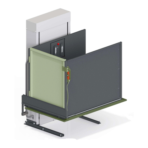
RAM Trus-T-Lift Owner's manual

TRUS-T-LIFT
SUPPLEMENTAL
MANUAL #
3
TALL TOWER TTL

RAM Elevators + Lifts 1-800-563-4382

1-800-563-4382 RAM Elevators + Lifts
Contents
Section 1: Introduction ...............................................................................................................................1
Section 2: Safety Information ...................................................................................................................1
2.1: Symbols and Definitions .................................................................................................................1
2.2: Additional Symbols .........................................................................................................................1
2.3: Safety Notes.....................................................................................................................................2
Section 3: Tall Tower..................................................................................................................................3
3.1: Hoisting and Positioning .................................................................................................................4
3.2: Anchoring the Tower ......................................................................................................................6
3.2.1: Top Tower Anchoring (Standard)............................................................................................6
3.2.2: Side Tower Anchoring (Optional)...........................................................................................7
3.2.3: 90 Degree Tower Anchoring (Optional) ................................................................................8

RAM Elevators + Lifts 1-800-563-4382
1
Section 1: Introduction
This supplemental manual has been provided to walk you through the safe and efficient
installation of a Trus-T-Lift Tall Tower Model. Please read this manual, as well as the main
installation manual, thoroughly before installing and operating your lift. We recommend your
lift and any add-ons be installed and serviced by a qualified technician.
Section 2: Safety Information
2.1: Symbols and Definitions
The following notations will be used through this manual to indicate areas that may present
special risks or consideration.
DANGER
Danger messages indicate an imminently hazardous situation, which, if not avoided, could
result in serious injury or even death.
Caution!
Caution messages indicate a potentially hazardous situation which, if not avoided, could
result in serious injury, death, or damage to equipment.
Note
Note messages provide information, such as reminders, general information or additional
guidelines that may provide guidance to the installer.
2.2: Additional Symbols
The following are additional symbols and conventions used through the manual:
A Detail callout, used to call attention
to a detailed mentioned in the body
of the instructions.
Step Callout, labels which step
the given diagram relates to
A
1

1-800-563-4382 RAM Elevators + Lifts
2
2.3: Safety Notes
Caution!
Read all instructions thoroughly before installation or use of this lift. Failure to follow the
instructions in this manual and the associated manuals for testing and operation could
result in serious injury or death. In addition, it will render RAM’s warranty null and void.
Do not connect or disconnect wiring while equipment power is on. Before servicing,
disconnect all power to the equipment. Failure to do so could result in significant injury or
even death.
System may start unexpectedly upon application of power. Unpredictable equipment
movement may result in serious injury or death. Use caution when applying power to the
unit during the installation process.
RAM Elevators + Lifts Inc. (RAM) disclaims any and all liability for any personal injury or
property damage resulting from the operation of a product that has been modified from the
original design. No person or company is authorized to change the design of the product
without written authorization by RAM.
Do not use an improper voltage source or a power source that provides poor quality power.
This may present a significant FIRE HAZARD and/or permanent damage to the equipment.
Do not override any of the safety devices provided with the lift. Doing so will likely lead to
serious injury or even death.
Ensure that there is nothing obstructing the carriage travel before operating the lift.
Ensure there is a minimum of 2in (50mm) and a maximum of 3in (75mm) clearance between
any part or edge of the carriage that could possibly be used as a supporting handhold and
any part of the fixed installation to prevent the trapping of a hand during the travel of the
carriage. See RAM installation drawings for details.
The lift is intended for use by people and not to be used for cargo or other purposes. Lifting
capacity is up to a maximum of 750 lb. unless otherwise noted on the lift and in RAM’s
supplied documentation. (DO NOT OVERLOAD THE LIFT). Overloading the lift will render
RAM’s warranty null and void.
This list of warnings may not be exhaustive, due care around equipment
should be observed

RAM Elevators + Lifts 1-800-563-4382
3
Section 3: Tall Tower

1-800-563-4382 RAM Elevators + Lifts
4
3.1: Hoisting and Positioning
Materials
Tools Components
Name #
Name #
Spreader Bar 1
Lift Tower 1
500lb Capacity Lifting Straps 2
Lifting Device 1
Instructions
Note that these steps are to be carried out after unpacking (section 3.4 in the main manual),
for the sake of properly positioning the lift.
DANGER
Under no circumstances should you attempt to lift or maneuver the tall tower by muscle
alone.
Before beginning, make sure that the spreader bar and lifting device you are using are rated
for the weight of your unit.
Not following either of these warnings can result in serious injury or death.
1) Wrap the straps around the front rectangular tube as shown in the below diagram ( A ),
approximately 5” in from the tower sides.
Caution!
Failure to use the recommended locations can produce unpredictable results. Confirm
proper placement before attempting lift.
1
A

RAM Elevators + Lifts 1-800-563-4382
5
Detail A: Spreader Bar
Detail B: 500lb Capacity Lifting Straps
2) Lift the tower until it sits flat on the ground near the lift’s final location.
3) Fasten the lift’s legs onto the tower as described in the main Trus-T-Lift manual in section
4.1:
“
Base Frame
” and continue the installation as normal.
2
Before releasing lift straps, fasten base
legs to tower. DO NOT ATTACH BASE LEGS
TO SUPPORT BASE AT THIS TIME.
B
A

1-800-563-4382 RAM Elevators + Lifts
6
3.2: Anchoring the Tower
Note
Do not anchor the lift tower to the wall unless you have completed sections 4.1 - 4.9 of the
main Trus-T-Lift manual, as well as the installation any landing devices as described in
“Trus-T-Lift Supplemental Manual #2 – Landing Devices”
. These instructions are the last to
be carried out before anchoring the base frame to the support base.
3.2.1: Top Tower Anchoring (Standard)
The standard method for anchoring a tall tower lift uses two pre-drilled holes in the back
panel of the lift, a spacer block, and anchors.
Note
We recommend your spacer block be at least 1/2" thick as to not interfere with the top cover.
Instructions
1) Drill two holes in the spacer block using the 1/4"
bit and the holes in the back of the lift as a guide.
Ensure that the holes are positioned such that the
block will not block the lift’s top cover. DO NOT
DRILL INTO THE WALL WITH THE 1/4" BIT. If pre-
drilling pilot hole for the lag bolts, use the 1/8” bit.
2) Proceed to fastening the tower to the wall with
the lag bolts. Note that the provided lag bolts are
made for wood; if fastening to something other
than wood, use lag bolts meant for that material.

RAM Elevators + Lifts 1-800-563-4382
7
3.2.2: Side Tower Anchoring (Optional)
In the event that your support wall does not
extend up to the mounting holes pre-drilled
in the top of the tower, wall mounting
bracket kits are available for purchase from
RAM. This kit comes with the mounting
bracket, magnetic spacer, bolts and
anchors, and a drill bit and tap.
Note
To properly mount the tower to the
support wall, the brackets cannot be
mounted more than 12” below your
top landing. If your support wall
does not extend this far, you will
likely need to use the 90 Degree
Mounting Bracket (see section 3.2.3)
Instructions
1) Place the magnetic spacer
inbetween the lift’s main structural
tube and the side panel. This spacer
prevents the side panel from being
warped.
2) Drill and tap holes centered on the main structural tube, through the side panel, spacer,
and structural tube.
3) Use the provided bolts and washers to mount the bracket to the side of the lift.
4) Anchor the lift to your support wall using the provided anchors. As with the other
methods, ensure your anchors are suited for the support wall material.
5) Repeat this process for the other side of the lift.

1-800-563-4382 RAM Elevators + Lifts
8
3.2.3: 90 Degree Tower Anchoring (Optional)
In the event that there is no suitable travel wall
directly behind the lift, RAM offers a 90 Degree
Tower Anchoring Bracket, which allows the
tower to be mounted to the lift’s travel wall.
Note
As with the previous method, this
bracket must sit no lower than 12”
below the lift’s top landing.
Instructions
1) Drill and tap mounting holes centered on
the rear structural tubes ( A ), through
the back panel and rear structural tubes.
2) Mount the bracket to the back of the lift using these holes and the provided bolts.
3) Anchor the lift into the wall using the other side of the bracket and the provided
anchors. As with the other methods, ensure your anchors are suited for the support
wall material.
Other manuals for Trus-T-Lift
4
Table of contents
Other RAM Lifting System manuals
Popular Lifting System manuals by other brands

Hy-Brid Lifts
Hy-Brid Lifts 1 Series MAINTENANCE & TROUBLESHOOTING MANUAL

WOOD'S POWR-GRIP
WOOD'S POWR-GRIP P1 COMPACT Series instructions

HiGH-LiFT
HiGH-LiFT YL-9FW Installation & operation manual

Blue Giant
Blue Giant LPJ-44 Operator's manual

Skyjack
Skyjack SJIII 6826E operating manual

WPG
WPG P1HV1102DC3 operating instructions