AFFORDABLE LIFTS KCSPM3648 Setup guide
Assembly And Installation Manual For
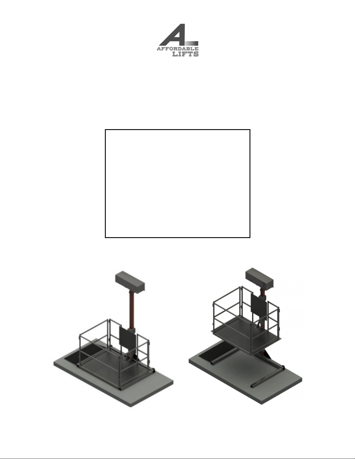
Affordable Lift Model KCSPM3648
Specifically For Serial Number E9997B
Manual Print Date: Dec 01, 2023, 12:50 PM EST
Lift E9997B Specifications:
Station Height:
38.0"
Weight Capacity:
500 lbs
Column Length:
78.0"
Color:
Gloss Black
Motor:
1500 lbs w/ Tethered Controller
Base:
Armed Base
Safety System:
Self Retracting Lifeline (SRL)
Column Bracing:
None/NA
Wheel Kit:
Yes
Rain Guard:
Yes
Battery Backup:
Not Purchased
Shipped As:
Disassembled
Shipped On:
On A Regular Pallet
All images in this manual are representational only.

Table of Contents
Click on a Section to jump to that section.
Section
Section Number
Introduction
Section 1
Safety
Section 2
Warnings
Section 3
Ter mi no lo gy
Section 4
Prepare to Install Your Lift
Section 5
The Wheel Kit
Section 6
Unpack Your Lift
Section 7
Remove Safety Guard
Section 8
Connect the Armed Base, Column and Hoist Assembly
Section 9
Attach the Platform to the Column
Section 10
Safety Backup System
Section 11
Electrical Power
Section 12
Connect Your Synthetic Rope
Section 13
Test Your Lift
Section 14
Adjust Your Lift’s Maximum Height
Section 15
Anchoring The Armed Base
Section 16
Finalize Column Bracing
Section 17
Reinstall Safety Guard
Section 18
Platform Gates
Section 19
Minimize Platform “Twist”
Section 20
Controller Storage Box
Section 21
The Transition Ramp
Section 22
Battery Backup
Section 23
Canopy Frame
Section 24
Maintenance
Section 25
Troubleshooting
Section 26
1. Introduction
Congratulations on your purchase of a new platform lift! We sincerely hope that this lift will help you accomplish the things that
are important to you and those you love.
Note:
If you are like me, then you hate reading instructions almost as much as you hate having to do things over because you
did it wrong. Unfortunately, this product can be assembled backwards, and doing so cannot be remedied without taking it
all apart and starting over. These instructions are specifically written to prevent those mistakes. So, please refer to these
instructions with each step, and have a pleasant assembly.
Note:
We have many of the assembly steps recorded on video for your reference. These videos are not a substitute for this
manual. They should be used alongside this manual. To find the videos use the video links throughout this manual or
Click
Here
.
Note:
The photos in this guide display lifts in various stages of installation. It is often the case that some recommended safety
feature is not yet in place in a specific photo. In particular, an anti-pinch point wall and a basic stair handrail are missing in
some of the scenarios we photographed.
Note:
There are some minor design changes between different lifts pictured here. These photos might not exactly match your
particular lift.
Note:
Even if your lift was shipped disassembled, some portions of it may have been pre assembled for you.
Note:
If your lift was shipped with some bolts and fasteners already in place and you find it necessary to temporarily remove
them, they must be re-inserted in the same direction. Inserting the bolt in the opposite direction may cause problems.
Note:
Throughout this document this is used as a caution symbol:
Please abide by all safety precautions so that you can
safely enjoy your lift and all that it has to offer.

2. Safety
2.1.
Safety is paramount!
If you have a question or concern about the safe installation or operation of your lift please call
Customer Support at (USA) 434-515-2321 (Provide your Serial Number 'E9997B' and contact information when you call).
2.2.
DO NOT USE YOUR LIFT OR ALLOW OTHERS TO USE YOUR LIFT IF YOU SUSPECT IT MAY BE IN AN
UNSAFE CONDITION
2.3. Warning:
No one should ride the lift until the Safety Backup System is installed and all lift testing is complete.
2.4.
Use common sense when installing or operating this equipment. Please read all the instructions before beginning
assembly and installation.
2.5.
The installer and operator are responsible for the safe operation of this equipment.
It is your responsibility to ensure
and verify that this equipment is safely installed. It is your responsibility to ensure and verify that inspections and
maintenance is done.
It is your responsibility to know and comply with all applicable legal codes and regulations regarding
your platform lift.
2.6.
Be sure to lift heavy objects using your legs, not your back.
2.7.
Do not allow children or people who are not able to understand the safe operation of the lift to use or play with the
controllers. Letting unqualified people operate the lift without supervision puts them and anyone around the lift at severe
risk. Allow only capable persons to operate the lift.
2.8.
"Pinch Point" risk is inherent in any mechanical device of this nature. This is the risk of something (such as a toe) getting
caught underneath something as the Platform ascends.
Inadequate vigilance and safety in pinch point risk areas can
cause injury or death or can harm your lift.
A common and prominent pinch point risk area is any gap underneath a
landing, such as a porch or deck. We recommend that you identify any such areas in and around your lift and take safety
precautions. Eliminate pinch point risk by covering openings below the landing with a vertical or angled plywood wall to
prevent body parts and items from being trapped between a landing or floor and the Platform as the lift ascends upwards
from the ground.
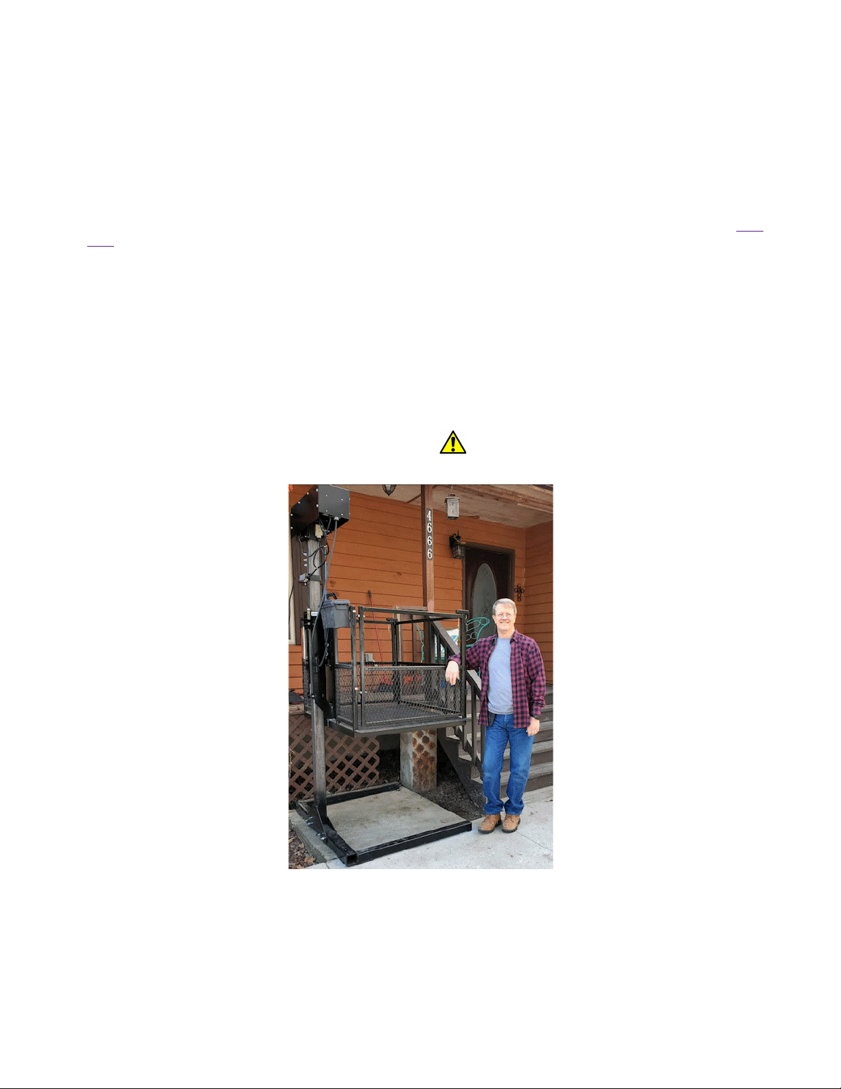
Below are two "shear points" before and after installing two different types of shear protection:
Misuse of this equipment can cause serious injury or even death

3. Warnings
Caution! Carefully read the owners manual and the following warnings prior
to use. Failure to comply with the following may result in serious bodily
injury, death, or damage to the lift. If you have questions, contact Customer
Support at (USA) 434-515-2321 (Provide your Serial Number 'E9997B' and
contact information when you call).
!"
Prior to use, ensure that the safety mechanism is in place properly. Never use a lift without a safety mechanism properly
installed and functional!
!"
Prior to each use, inspect the cable and components for signs of fraying or damage.
!"
Always lock gates prior to use. Never operate the lift with any gates unsecured.
!"
Always lock/secure wheelchair or cargo from shifting while in use.
!"
This lift is to be used exclusively for the transport of cargo or a wheelchair and occupant and an additional adult where
assistance is required.
!"
Improper use of lift may result in personal injury or damage to the lift. All users must read and follow operating
instructions prior to use of lift.
!"
Ensure that the lift is properly installed and is stable prior to use of the lift. Failure to ensure proper installation may result
in an increased risk that the lift will tip over or otherwise malfunction, resulting in damage to the lift and/or personal injury.
!"
Do not exceed the maximum load capacity.
!"
Remain in the correct, upright position while the lift is in use. Keep entire body within the lift at all times. Failure to
remain in position may result in pinch or crush hazards at the deck/flooring platform and property damage or personal
injury from a malfunction of the lift or falling from the lift.
!"
If the lift is installed to go through an opening to another level, it is particularly important to never rest arms, feet or limbs
on handrails or extending from the lift. Narrow openings pose a substantial risk of injury to the lift or serious personal
injury.
!"
Prior to use, ensure that electrical power is installed on a grounded electrical circuit.
!"
Prior to use, inspect for proper function, required maintenance, or damage. If a problem exists, cease use of the lift
immediately. Do not attempt to make repairs or alterations to the lift. Contact a licensed professional or customer support
for any necessary repairs.
!"
Do not conduct any maintenance, repairs, or otherwise work on this lift while it is operational or plugged in unless
instructed to do so by customer support.
!"
Do not alter or modify this lift or any of its safety devices in any way.
!"
Do not expose any electronic part of this lift to liquid or harsh weather conditions.
!"
Do not use if snow, ice, or other debris have accumulated on the lift.
!"
Do not operate this lift in the presence of combustible or explosive gas or fumes.
!"
Completely disconnect the lift from its power source prior to cleaning the lift.
!"
Do not operate this lift if you are under the age of eighteen (18) years old. All users of this lift who are under the age of
eighteen (18) years old must be accompanied by an adult who is authorized to use this lift and has read its operating
instructions.
!"
Keep children away from this lift at all times unless using this lift while accompanied by an authorized adult who has
read its operating instructions.
!"
Do not stand or place any body part under the lift platform at any time.
!"
When using the lift, ensure that no persons, pets or objects are in the upward or downward path of the lift platform or
collar.
!"
Keep all loose articles, hair, and other objects away from the moving portions of the lift at all times.
!"
Keep hands and feet away from moving parts while the lift is operational
!"
Do not store any items or objects on or under the lift platform.
!"
Store lift in a temperature controlled, dry environment when not installed for use.
!"
Ensure that the lift platform is fully in the down position and all electrical components are disconnected from power prior
to moving the lift.
!"
Use appropriate lifting/transport precautions when moving the lift. The lift is very heavy.
!"
Keep lift controllers in a secure location out of reach of children.
!"
Remain aware of your surroundings and ensure you are able to hear well at all times while the lift is in use
FAILURE TO COMPLY WITH ANY OF THE ABOVE WARNINGS MAY RESULT IN
SERIOUS BODILY INJURY, DEATH, CRUSH, ELECTRICAL, TRIPPING
HAZARDS OR DAMAGE TO THE LIFT.
4. Terminology
4.1.
Front, Back, Right and Left Sides:
The Column is located on the back side of the lift. The side of the lift opposite the
back side is the front side. Right and left are determined when you face the lift's Platform from the front.
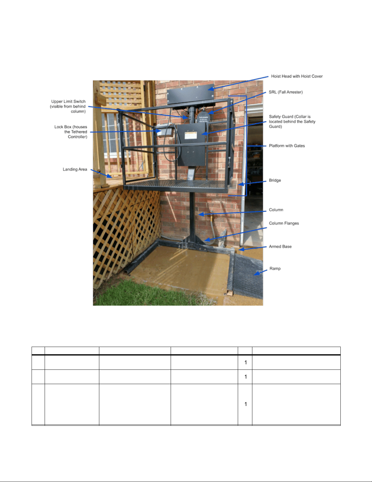
4.2.
Please look over the sample photo below to familiarize yourself with the important parts of your Affordable Lift.
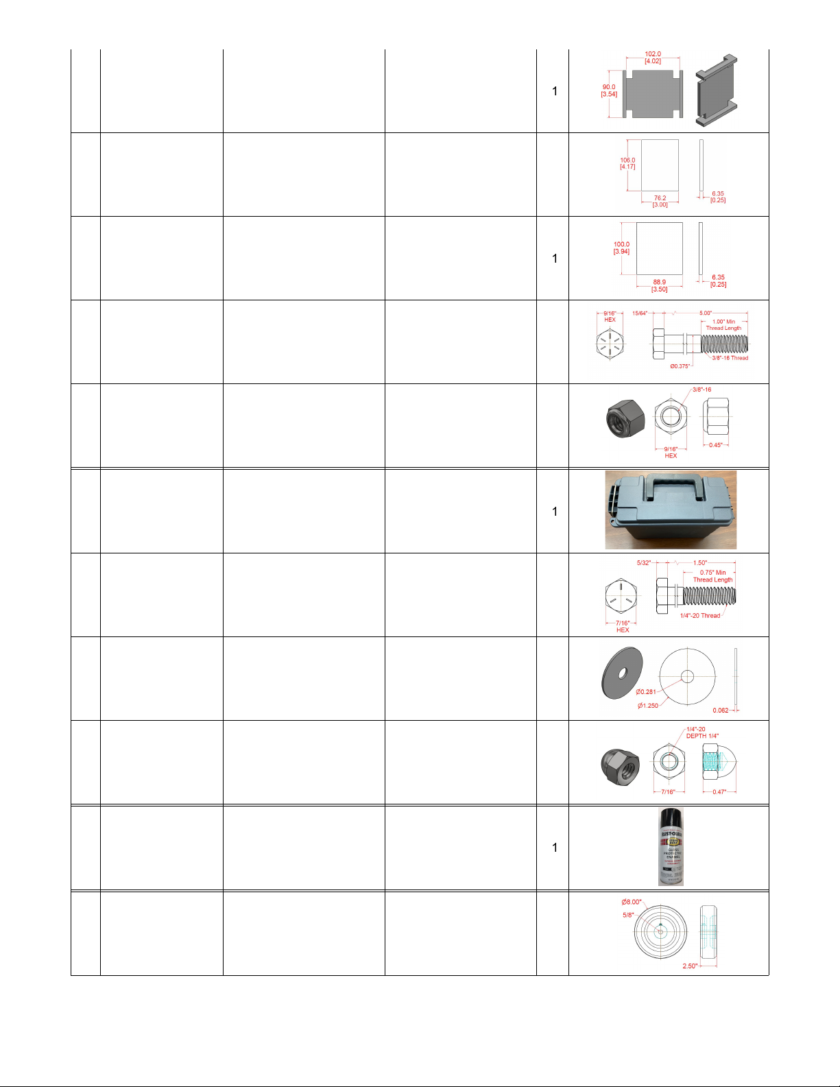
Below are the names and images of lift parts and components that were
shipped to you:
Row
Part Number
Item
Description
Qty
Sample Image
1
Welcome Letter
Welcome Letter and
Instructions
1
None
2
Packing List
List of all parts and
components shipped
1
None
3
Assembly and Installation
Manual for the KCSPM3648
Also available via email
on request - call (USA)
434-515-2321 (Provide
your Serial Number
'E9997B' and contact
information when you call)
1
None

4
Affordable Lift -
Disassembled
42.0"x52.0"x35.2", Gloss
Black
1
5
Hoist Assembly - 1500 lbs
w/ Tethered Controller
8.25"x26.0"x7.5", Gloss
Black
1
6
RTS3x3x.25X78
Standard Steel Lift Column
- Flanged
3.5"x20"x83"x1/4" (.25") -
70 lbs
1
7
AWB52x40
Base with Arms
52.0"x40.0"x3.25", Gloss
Black
1
8
HBH0.5-13x5
Base with Arms - Bolts
.5"-13x4.5" Grade 8
4
9
Base with Arms - Washers
.5" SAE
4
10
HNN0.5-13xNylock
Z
Base with Arms - Nuts
.5\"-13 Nylock Nuts
4
11
SRL Unit
Fall Arrestor with hook
1
12
SRL Pulley
4.25"x2.75"x1" (Shipped
attached to Collar)
1
13
6000144GA
ULS Rain Guard
5"x3"x3" Galvanized
Sheet Metal
1
14
6000107
Actuator Spring
3"x3"x1" Steel
1
15
6000106
Collar - Backing Plate
3.5"x4.7"x1" Plate
1
16
6000014
Collar - Regular Slip Pads
.25"x3"x4.1"
5
17
6000013
Collar - Backing Plate Slip
Pad
.25"x3.5"x3.9"
1
18
HBH0.375-16x5
Collar - Bolt
3/8"-16x5"
4
19
HNW0.375-16x
Collar - Bolt - Nylock Nuts
3/8"-16 Nylock Nuts
4
20
3500010
Controller Storage Box
7.1"x11.6"x5.1"
1
21
BHM40.25-x
Controller Storage Box -
Bolts
.25"-20x1.5"
2
22
HWA0.25-1.25
Controller Storage Box -
Washers
.25"x1.25"
2
23
HNA0.25-20x
Controller Storage Box -
Nuts
.25"-20 Acorn Nuts
2
24
Spray Paint Can
Rustoleum Protective
Enamel, Gloss Black, 12
oz
1
25
3500009
Wheel Kit - Standard
Wheels
8"x2.5"
2
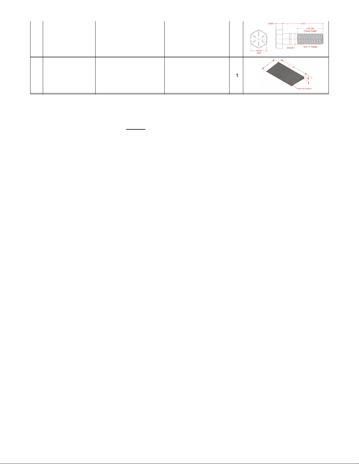
26
MW82.5x 0.625xX
Wheel Kit - Bolts
5/8"-11x4"
2
27
6000111
A16B33C2.75
Left Side Ramp
A16"xB33"xC2.75", Gloss
Black
1
5. Prepare to Install Your Lift
5.1. We Are Here To Help:
We would much rather have you call us for help than have you assemble or install your lift
incorrectly. Your lift's serial number is
E9997B
. If you have questions or problems during assembly please call Customer
Support at (USA) 434-515-2321 (Provide your Serial Number 'E9997B' and contact information when you call).
5.2. Receiving Your Lift:
If damage has occurred during shipping immediately document it with photographs and notify our
Shipping Department at (USA) 434-207-8444 (Provide your Serial Number 'E9997B' and contact information when you
call). Check your lift for damage before signing the papers with the delivery man, when applicable. If there is damage, note
it on the delivery paperwork appropriately and notify Affordable Lifts.
If damage is found after the delivery papers are
signed, we will not be able to file a claim for the damage with the shipping company on your behalf.
5.3.
We recommend that at least two adults work together to assemble this lift. Some parts of your lift are quite heavy and
having two or more people assemble your lift reduces the risk of injury. Affordable Lifts is not responsible for injuries that
occur while assembling or utilizing your lift.
5.4.
Most customers prefer their lift be oriented for straight-through travel. This means entering one side of the lift (right or left)
going up and then continuing out the other side (right or left). Sometimes this is not practical. If you are using a wheelchair
or walker, remember to allow adequate space to navigate onto and off of your lift's Platform.
5.5.
We recommend that if possible, the Column side of the lift be installed closest to a nearby wall. If bracing is desired, then
this positioning will make bracing easier.
5.6. Before you begin:
!"
The installation site should be flat and level, or you should be prepared to use steel or plastic shims to level
your lift.
!"
The installation site should be clear of debris and as accessible as possible.
!"
Your lift weighs approximately 450 lbs and it has a Platform weight capacity of 500 lbs. Be sure that the floor of your
installation location can support this combined weight.
!"
The lift should sit on a solid surface (concrete, asphalt, solid flooring, etc) or substantial pavers. Anchoring on asphalt
installation requires inserting steel anchors into an epoxied hole.
!"
Pinch point protection should already be installed.
!"
If you remove a section of a landing railing then, if the landing is high enough you should install a safety gate in its place.
!"
Children and pets should be excluded from the area during assembly and installation.

6. The Wheel Kit
6.1.
Your lift was shipped with a detachable Wheel Kit. We will discuss the Wheel Kit now because you may choose to use it
in the next steps.
The Wheel Kit consists of two 8" wheels and their axle bolts. These wheels allow the lift to be tilted backwards and wheeled
over a smooth hard surface.
Here is a photo of the Wheel Kit after installation:
While this is an easy way to move the lift, it is still a two person operation.
These wheels should always be removed prior to actually using the lift.
6.2. Wheel Kit Installation or Removal:
1.
Locate the wheel mounting points on the back of the Base. Use a pry bar to lift the corner of the base up about 1".
2.
Place the bolt through the wheel as shown in the photo above.
3.
Use a wrench to secure the wheel by tightening the bolt.
4.
Reverse this process when removing the Wheel Kit.
6.3. Using The Wheel Kit:
1.
With one person at the back of the lift and one person at the front, tilt the lift backwards so that it is balanced on its
wheels.
2.
Carefully move the lift along a flat, hard surface to its desired position.
3.
Remove and store the Wheel Kit once the lift is in place.
7. Unpack Your Lift
7.1. Keep in Mind:
As you unpack,
watch out for any shipping damage
. If you sign for a damaged lift without noting
shipping damage you will not be able to make a claim later.
7.2. Small Parts:
Look inside the grey Controller Storage Box to see what small parts and paperwork it contains.
7.3. Unbolt the Platform:
Use a wrench to unbolt the Platform from the pallet and slide it forward off the pallet to one side.
7.4. Move the Base:
Lift up the Armed Base from the pallet and move it off to one side.
7.5. Unpackage the Column:
Your lift's Column is packaged separately. Remove any column packaging and check to make
sure that your Column
tube
is 3" x 3" x 78.0".
7.6. Weather:
Electrical components should be protected from weather until properly installed. For example, do not leave
your Hoist Assembly upside down where water can accumulate in it and damage the motor.
8. Remove Safety Guard
8.1.
Remove the Safety Guard from in front of the Collar. You will reattach it after finishing the next several steps. Be sure to
not lose the four acorn nuts.
9. Connect the Armed Base, Column and Hoist Assembly
Here is a video of this step:
Click here
9.1. Assembly Location Versus Final Location:
Assembly is easiest if you have ready access to all sides of the lift. So we
often do most of the assembly two or three feet from the final position and then move the lift to its final position towards the
end of the assembly process.
9.2.
The Armed Base has four anchor pads. Be sure that these pads are positioned on the floor side of the base.
9.3.
Lower the Column over the Base so that the Column flanges straddle the back beam of the Base.
It is
IMPORTANT
that
the smaller, shorter Column flange is on the inside of the base (towards the side with the base arms).
When looking
straight along the Column beam ensure that it is parallel with the back beam of the base.
Failure to make the Column
parallel with the Base will make bolt hole alignment difficult, and bolt insertion impossible.
9.4.
Line up the bottom hole in the flange with the end hole of the four (4) hole pattern in the Base. In the case of the
illustration below, the BOTTOM hole of the flange must be aligned with the LEFT most hole in the Base.
9.5.
Insert a ½-13 x 4.5" Hex head bolt through the bottom hole.
Insert the bolt from the arm side of the Base.
Do not put
the washer on the bolt head end of the bolt. By design, the holes are snug on the bolt. It will probably be necessary to tap
the bolt through the beams. Do not beat on the bolt if the holes are not aligned. Doing so will only ruin the bolt.
9.6.
Install a washer and nylock nut together on the bolt.
DO NOT TIGHTEN.
This bolt will serve as a pivot point when you
later set the Column upright.
9.7. Prepare To Attach The Hoist Assembly:
To attach the Hoist Assembly you may proceed one of two ways. For most
assembly situations the first set of steps is easiest. Each step is described in detail further below.
1.
Pivot the Column to its vertical position.
2.
Insert the remaining 3 flange bolts
from the arm side of the Base
and tighten all 4 flange bolts to secure the Column.
3.
Place the Hoist Assembly on the top of the Column.
OR
1.
Place the Hoist Assembly on the top of the Column.
2.
Pivot the Column to its vertical position.
3.
Insert the remaining 3 flange bolts and tighten all 4 bolts to secure the Column.
Here are more detailed explanations of each of the above steps. Depending

on your situation you may choose to do them in different orders, as outlined
above.
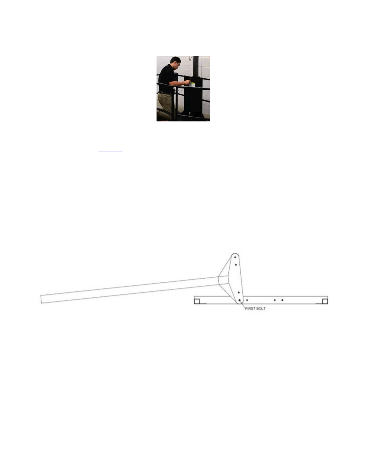
9.8. Pivot the Column to Its Vertical Position:
For tall lifts, please take extreme caution during this step. Depending
on its length your Column could weigh over 200 pounds.
Consider obtaining scaffolding, ladders, or other equipment so that you can safely do some of these steps. If you are not
sure you can complete these steps, we recommend hiring a local handyman. Before doing this first step you may wish to
move the Platform onto the end of the base arms to secure the base, as shown below.
Note that the drawing below does not show any Hoist Assembly on the upper end of the Column.
Be careful around the lift at this point. Especially if the lift is not on a level surface or you try to move it. Without the
weight of the Platform, the lift is top heavy and not very stable. This is even more true once the Hoist Assembly is mounted
on the Column top.
9.9. Insert Remaining 3 Flange Bolts:
Insert the remaining 3 bolts holding the Column to the base.
Insert the bolt from the
arm side of the Base.
Do not put the washer on the bolt head end of the bolt. It goes on the other end. Tighten all four
bolts to 80 ft/lbs.
9.10. Place Hoist Assembly Onto The Column:
There are two ways to do this. For most assembly situations the first set of
steps is easiest.
Use Caution When Handling the Hoist Assembly.
!"
The Hoist Assembly is a heavy object. Use care when lifting.
!"
The electrical cables are easily damaged.
1.
Lean the top of the Column down onto a solid support. This solid support could be the intended landing. Make sure both
ends of the Column are secure and will not slide.
2.
Slide the Hoist Assembly onto the end of the Column, oriented so that the hoist cable will run down the front of the
Column.
3.
Carefully set the lift upright on its base.
OR
1.
With the Column upright, use a scaffold, deck or other structure to safely access the top of the Column. You may wish to
temporarily lean the Column slightly or rotate the base to position the Column's top nearer to your landing.
2.
Carefully lower the Hoist Assembly onto the Column, oriented so that the hoist cable will run down the front of the
Column.
10. Attach the Platform to the Column
Here is a video of this step:
Click here
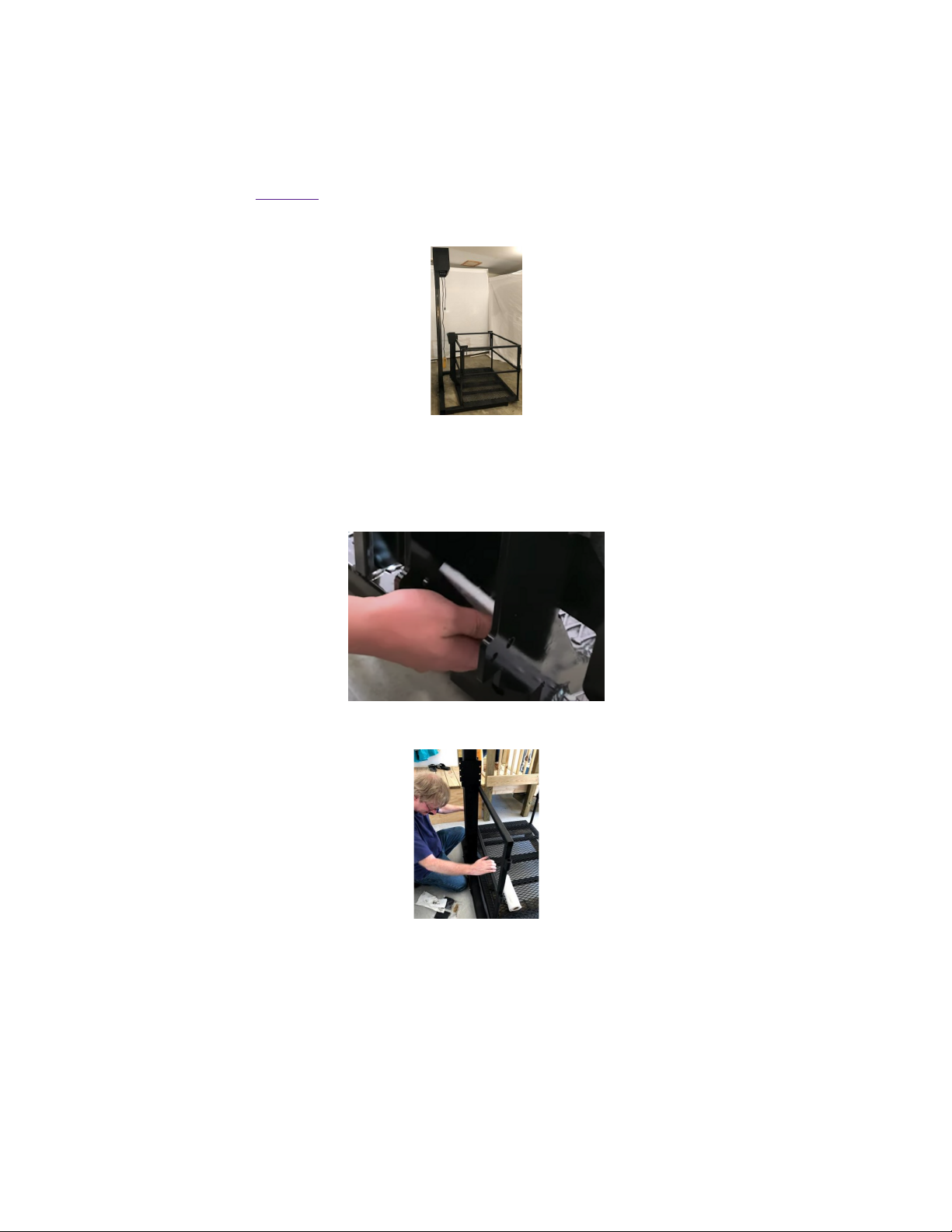
10.1.
Line up the Platform and Collar. Move the Collar to about a foot away from the Column.
10.2.
Clean all plastic Slip Pads of dirt and debris. Ensure that they remain clean throughout the assembly process. You have
five Slip Pads that are have a common size (Part Number 6000014) and one Slip Pad that is a unique size (Part Number
6000013). The unique Slip Pad will be installed last. Take one of the common-sized Slip Pads and put a little grease or
petroleum jelly on one side of the pad. Use the grease to stick the Slip Pad to the inside front of the Collar between the pad
retainer rails near the bottom of the Collar.
10.3.
Slide the Platform back so that the Collar surrounds the Column.
10.4.
Ensure that the Slip Pad you just installed has not fallen out of position. Now insert a common-sized Slip Pad into each
of the two pockets found along either side of the
lower
Collar. If the fit is a bit tight you may need to tap the Slip Pad with a
hammer and screwdriver, jiggle the Platform or use a screwdriver to widen the opening.
Note:
There is no back side Slip Pad for the lower Collar.
10.5.
Loosely
secure the lower Collar bolt and lock nut.
If you over tighten then the Platform will not descend properly under its own weight.
10.6.
Insert a common-sized Slip Pad into each of the two pockets found along either side of the
upper
Collar. If the fit is a bit
tight you may need to tap the Slip Pad with a hammer and screwdriver, jiggle the Platform or use a screwdriver to widen the
opening. After this step you should have only one Slip Pad left to install.
Note:
The front side of the Collar does not get a Slip Pad.
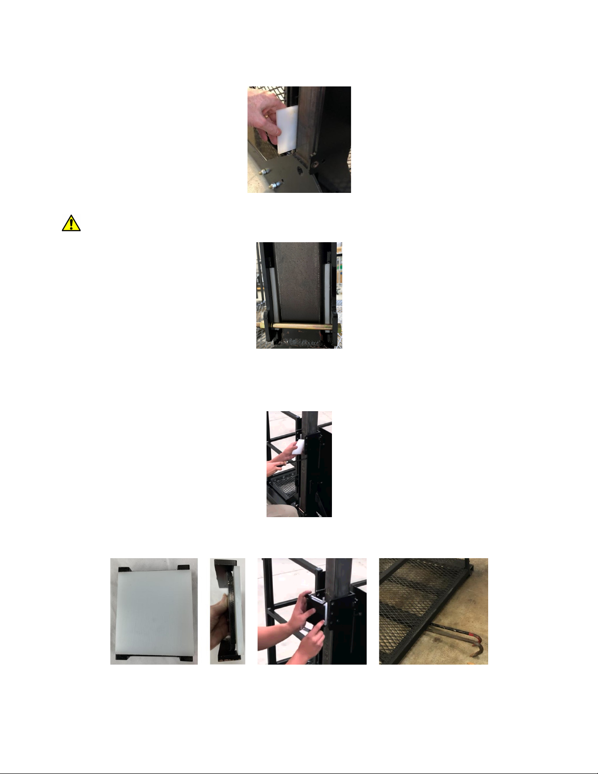
10.7.
Position the remaining Slip Pad on the Backer Plate and insert the Backer Plate into the Column as shown below. You
may need to lift the front of the Platform slightly to bring the top of the Collar closer to the Column to make this step easier.

10.8.
Install the Upper Limit Switch Actuator Spring (a silver L shaped piece of sheet metal with holes on one side) and
secure the Backer Plate as shown in the photos below. The Slip Pad must be against the Column.
The Upper Limit
Switch Actuator Spring is critical and prevents your Upper Limit Switch from being crushed.
There is no top or
bottom end for the Backer Plate. Tighten the three bolts used here.
10.9.
It is critical that the lower Collar adjustment bolt is adjusted properly. All Collar bolts have nylock nuts. The lowest
Collar bolt does not need to be tight to work properly. If the lowest Collar bolt is too tight, the Platform may bind on the
Column and may not descend as the hoist unspools the synthetic rope. If this happens, the hoist may produce several
inches (or feet) of slack, and the Platform may then fall until the slack is used up, or the Platform will fall until the anti-fall
device locks up and stops the platform. Either condition is undesirable.
Later in the installation process we will adjust the single bolt on the back, near the bottom of the Collar so that side to side
wobble is minimized and the unit descends smoothly with no weight on the Platform.
11. Safety Backup System
EVERY LIFT MUST HAVE A SAFETY BACK UP SYSTEM. NEVER OPERATE THE LIFT WITHOUT AN
OPERATIONAL SAFETY BACK UP SYSTEM.
Your lift is equipped with a Self Retracting Lifeline (SRL). See below:
11.1. Installing your SRL:
Your SRL color, model and its cable or strap may be different from what is shown here. Your SRL
should be inspected yearly for wear and tear.
Here is a video of one way to install the Safety Backup System:
Click here
The SRL should always retract smoothly and completely when the Platform is at the upper station. If this
does not happen, do not allow anyone to use the lift and call Customer Support at (USA) 434-515-2321 (Provide
your Serial Number 'E9997B' and contact information when you call).
1.
Always use gloves when touching wire rope.
2.
Secure the carabiner at the top of the SRL body through the outer hole on the Hoist Head.
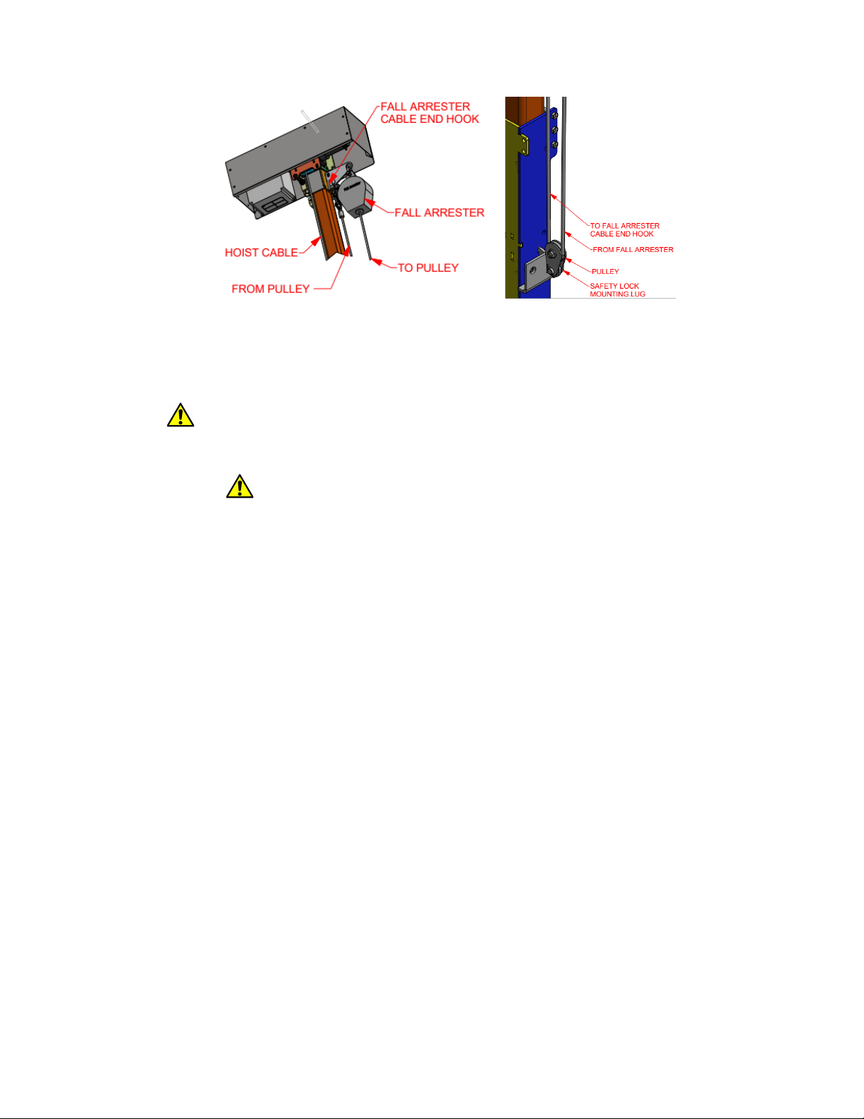
3.
With the wire rope running through the pulley, attach and secure the SRL cable pulley to the Safety Lock Mounting Lug
on the right side of the Column midway down. Do so by inserting the pulley's carabiner or bolt through the holes at the
bottom of the pulley. See the photo below.
4.
Attach the SRL’s cable hook to the inner hole on the Hoist Head.
5.
Test the SRL by using a
gloved hand
to sharply pull the cable down from the SRL body. It should engage and lock. Let
the cable retract slowly.
12. Electrical Power
12.1. Warning:
When the hoist is connected to electrical power, anyone with a Controller can cause it to activate.
Before plugging in the lift or working on any part of the lift always be sure that no one is pushing any buttons on any hand
held Controller.
12.2. Controller Access:
Controllers should always be kept away from children or those who should not operate the lift
without supervision. The Controller Storage Box has a hasp and can be locked using a customer supplied lock.
12.3. Power Source:
!"
You have an AC motor that requires 120 volt AC power.
!"
Your lift should never require more than 15 amps of electrical power.
!"
Avoid plugging your lift into any circuit that cannot support at least 20 amps or is shared with heavy machinery that
might, together with the lift, trip the circuit breaker.
!"
GFI protected electrical outlets must be used in all locations that might be exposed to water.
!"
You may use an extension cord to bring power to your lift, but it must be 12 gauge or thicker.
!"
Be sure that electrical power cords will not be crushed, punctured or have their insulation worn through.
!"
When installing your lift anywhere where the power cords may be exposed to water you must use weatherproof
extension cords and weatherproof extension cord connectors.
12.4. Plug in the hoist motor power cord into a suitable outlet.
12.5. Power Cord:
Consider using a zip tie to secure any excess power cord out of the way so that it will not rub or chaff.
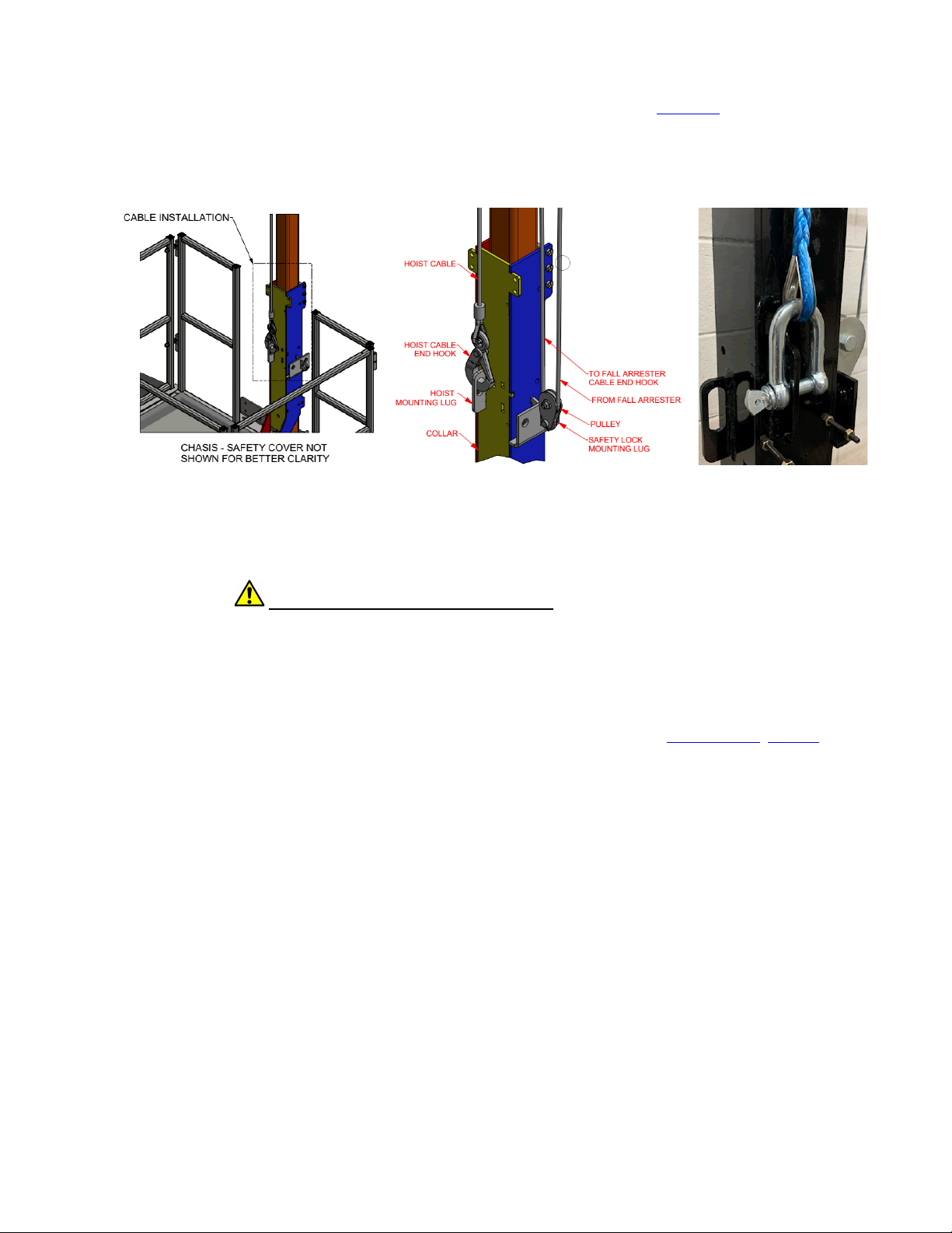
13. Connect Your Synthetic Rope
13.1. Attaching the Synthetic Rope:
Here is a video of attaching your lift's synthetic rope:
Click here
1.
Connect your hoist motor to electrical power.
2.
While lightly pulling your synthetic rope, use your Controller to unspool enough synthetic rope to reach slightly past the
hoist mounting lug.
3.
While keeping slight tension on the synthetic rope, securely connect the hook or carabiner to the hoist mounting lug on
the
front
of the Collar.
4.
Use your Controller to take up any slack in the synthetic rope.
5.
Ensure that the synthetic rope does not contact any bolts, studs, brackets, etc.
6.
Proceed to the next step to test your lift.
14. Test Your Lift
14.1. Take a Test Run:
with no one on or under the lift's Platform.
Now that your lift is positioned and plugged into your power source, on your tethered hand held Controller push the “Up”
button to tighten any loose synthetic rope. Then go up several inches and all the way back down again. Be sure to not go
up more than several inches. The motor should turn off when you reach the ground. After you successfully do this several
times you may send the Platform higher, but remember that you have not yet installed your Upper Limit Switch.
Do not
allow your Collar or Actuator Spring to collide with your Hoist Assembly.
14.2. Troubleshooting:
If you run into any issues during testing you may wish to consult the
Troubleshooting Section
at the
end of this document.

15. Adjust Your Lift’s Maximum Height
15.1. Upper Limit Switch:
Your lift has an Upper Limit Switch that automatically stops the Platform at a preset station height.
This is an important safety feature.
You can set this height easily using the 1/8" allen wrench supplied with the lift, taped
on to the Upper Limit Switch bracket.
The switch is clamped onto the column as shown below. Please note that the Upper Limit Switch must be actuated by the
Actuator Spring shown in the photo.
You will damage the Upper Limit Switch if the Actuator Spring is not properly
installed.
15.2. Attach And Adjust the Upper Limit Switch:
To see a video of this step
click here
1.
Do NOT stand on the Platform while doing this.
2.
Place the Upper Limit Switch bracket onto the Column as you see below. The switch goes on the back of the Column.
The plunger faces downward. Slide the Upper Limit Switch up or down on the Column until the bottom of its mounting
bracket is 33” above your landing height.
3.
Slide the Upper Limit Switch downward until the switch touches the Actuator Spring and also makes a click sound.
4.
Using a 1/8" allen wrench, tighten the set screw in the bracket holding the Upper Limit Switch.
5.
Raise or lower the Upper Limit Switch to make the Platform stop higher or lower.
6.
Note that landings are not always level, nor are their edges always square.
7.
Tip:
If your Upper Limit Switch is at a good height and you find you need to temporarily move it, first mark its current
position on the Column for later reference.
15.3. Attach The Upper Limit Switch Rain Guard:
1.
If the lift is exposed to severe weather, a Rain Guard (PN 6000144) should be used to prevent water from entering the
switch.

2.
The photos below show a Rain Guard installed over the switch.
3.
To install the Rain Guard, loosen the Upper Limit Switch set screw, slide the Rain Guard tab down between the Column
and the Upper Limit Switch mounting bracket, as in the photo below. Then tighten the Upper Limit Switch set screw.
16. Anchoring The Armed Base
16.1.
Depending on local building codes, anchoring the armed base of a lift of this height may be optional. But we do
recommend it to keep your lift from shifting over time.
NOTE: If you use shims then you must also anchor your base to
prevent it from shifting off of your shims.
16.2.
Here is how to anchor your Armed Base:
1.
Be sure the Armed Base is
exactly
where you want it long term.
Run your Platform up and down its full travel
to check for any collisions.
You may even want to initially anchor your Platform at only two points so that you can later
easily adjust the base location and use the other anchor points.
Once anchored at all points, your lift's location will
be very difficult to adjust.
2.
Make sure the gates are properly aligned, working and properly interacting with the landing railings.
3.
For the measurements below please remember that many walls are not truly vertical. If you are placing your Column
near a wall use a plumb bob to determine the vertical plane of the wall and any obstructions.
4.
Use a plumb bob to determine the vertical plane of a landing's edge. Remember that many landings are not square and
many landings are not level.
5.
Be sure to also consider water spigots, electrical outlets and other items that might obstruct the path of the Collar or the
Platform itself.
6.
If you will use your Platform's left opening at an upper landing, then
the left side of your Column should be 25.0"
from the edge of that landing
. This number includes a 0.5" (1/2") gap between the edge of your Platform and your
landing.
7.
If you will use your Platform's right opening at an upper landing, then
the right side of your Column should be 25.0"
from the edge of that landing
. This number includes a 0.5" (1/2") gap between the edge of your Platform and your
landing.
8.
If your Platform's front side passes by an obstruction, then
the front side of your Column should be at least 37.75"
from that obstruction
. This number includes a 1" gap between the edge of your Platform and that obstruction.
9.
For the Collar to ascend and descend without hitting any obstruction the back side of the Column must be
at least 1.75"
from a vertical plane that includes any obstruction in the Collar's path.
10.
There are four anchor pads built into the Armed Base. Each has a 0.5" (1/2") pre drilled hole.
11.
Decide on what diameter and length anchors to use based on your floor material. We recommend anchors at least 3"
long.
12.
Drill the anchor holes. Consider drilling deep enough so that the anchors can be hammered down into the floor if the lift
is ever removed.
13.
Insert and tighten the anchors. If you elevate the Platform in order to do this, make sure the Platform is secure before
you work under it.
17. Finalize Column Bracing
17.1.
For your particular lift you do not have to anchor the top of the lift to a strong structure. However many people prefer to
do so as this minimizes any Platform "bounce".
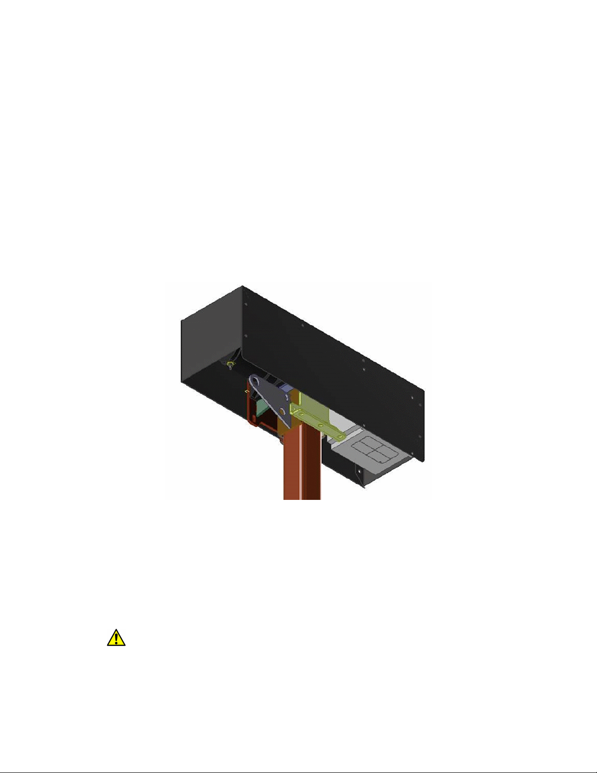
17.2. Back Flange Brace:
Your Hoist Assembly has a Back Flange with 3/8” diameter holes (three vertical and two
horizontal) that can be used for bracing the lift’s Column. They are visible in the drawing below. On your lift this flange is
located approximately 76" from the ground.
Connect your brace to a strong structure using steel angle iron or equivalent.
18. Reinstall Safety Guard
18.1.
Now that all of your wires and hoist rope have been installed, re-attach your Platform's Safety Guard to the Collar using
the four acorn nuts you removed earlier. Be sure to reinstall it so that the nameplate sticker is visible and right side up.
19. Platform Gates
19.1. Platform Gates:
Each gate comes pre-attached to the Platform, hinged on the side specified in your Order. Gate and
latch styles may vary.
For most lift configurations you can easily detach a gate and reverse its swing direction.
19.2. Safety:
It is important that all gates shut easily and securely, and that all gates be shut and latched before using
the lift.
Unsecured gates can catch on items as the Platform moves and severely damage the lift, or people could
fall off of the Platform and be injured or killed.
Other manuals for KCSPM3648
1
This manual suits for next models
1
Table of contents
Other AFFORDABLE LIFTS Lifting System manuals

Popular Lifting System manuals by other brands


TradeQuip
TradeQuip 1030 owner's manual

NAUSICAA
NAUSICAA Weighing System user manual

Faraone
Faraone ELEVAH 70 Use and maintenance instructions

TECALEMIT
TECALEMIT TEC 3000X Installation, operation and maintenance instructions

WERTHER INTERNATIONAL
WERTHER INTERNATIONAL 280AZ manual

Pro-Lift
Pro-Lift T-5500 Operating instructions & parts manual


