TECALEMIT TEC 3000X Manual

Installation, Operation and
Maintenance instructions
3000X Screw Hoist

2
3
Safety Precautions
Do not raise or lower the hoist when people are under
near or on the top of the hoist or vehicle.
Always watch the vehicle while raising or lowering.
Always consider the vehicle stability before removing or
adding parts.
Do not use the hoist motion for removing or adding
parts.
Some vehicles are not suitable for lifting on a 2 post hoist.
e.g. Toyota Landcruiser 80 series.
Always keep the lifting pads clean and in good condition.
Use only Tecalemit approved lifting accessories.
This hoist is designed for raising vehicles. Do not use it for
any other purpose.
Do not have vehicle engine running on hoist unless
absolutely necessary, to avoid injury from the hot exhaust
or rotating parts.
Always turn the isolating switch to the horizontal “o”
position when stopping the hoist after raising. Switch-
ing to the “o” position will immediately stop the hoist
if there is any malfunction and will isolate the hoist and
protect the operator should the electrics be damaged in
any way.
In an emergency or when servicing, turn the isolating
switch to “O” and padlock it.
Do not directly spray or hose the hoist with water as it will
eventually cause corrosion and shorten the life of the
Contents
Page Subject
3-5 Installation Instructions
6-7 Operating Instructions
To Raise Hoist
To Lower Hoist
Routine Maintenance
Major Service
8-9 Fault Diagnosis
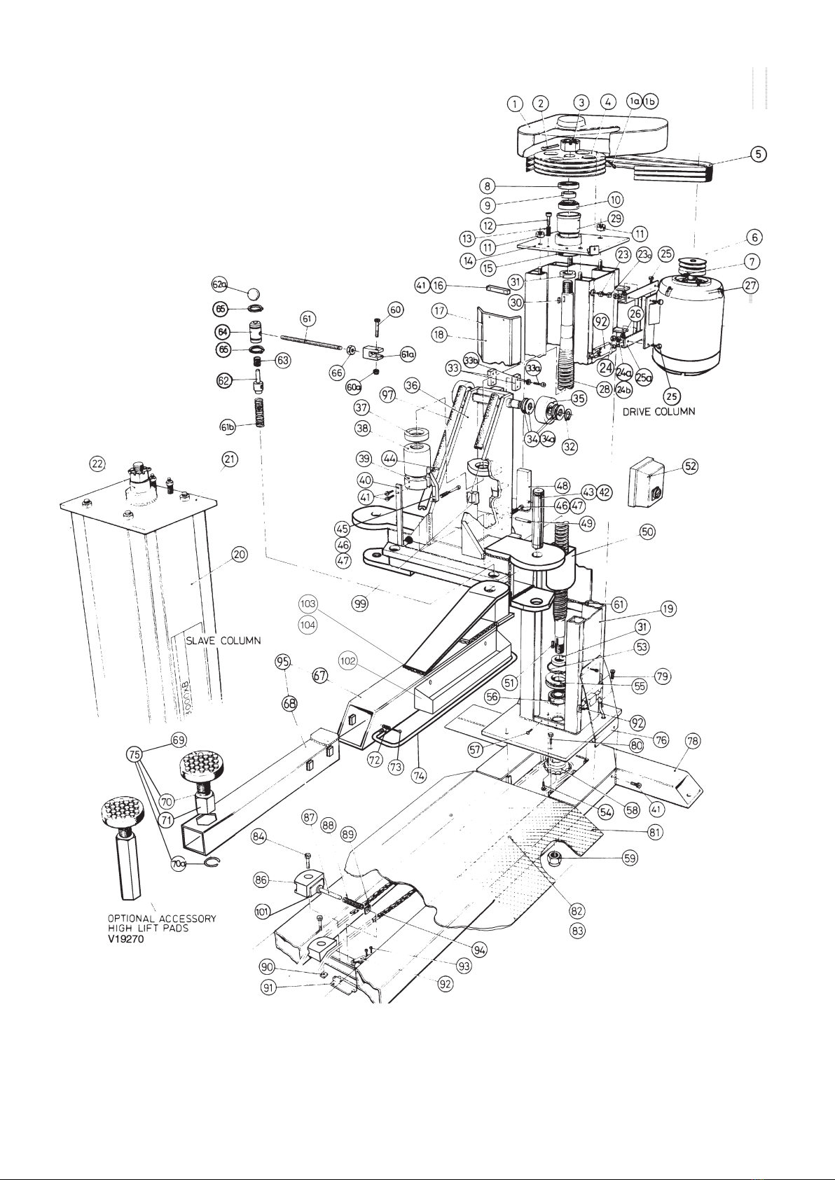
10-11 Illustrated Parts Lists
hoist. The hoist is not suitable for operations that involve
washing of the vehicle.
(If washing down the oor around the hoist, raise the
arms 200 mm o the oor so the hole in the column
blind is covered by the carriage to prevent any overspray
entering the oil reservoir.)
TEC3000X Statutory Design Approvals and
References
Australia
State Approval Reference No.
South Australia SD 97132-1
Western Australia Refer to S.A.
New South Wales Not Required
ACT Refer to S.A.
Northern Territory Refer to S.A.
Queensland Q16369
Tasmania Refer to S.A.
Victoria Refer to S.A.
Electrical approval MC1S/AO
(Electricity Trust of SA)
New Zealand Not Required
2
3
Installation Instructions
By following these instructions carefully, your new hoist can be
assembled quickly to give safe, smooth and ecient operation
and an extended, trouble-free life.
Note: Use lifting equipment or extra people to lift & handle the
heavy parts.
1. The hoist must be installed under cover on a at concrete
oor of minimum tensile strength Grade 25 MPa and minimum
thickness 100 mm with at least one layer of F72 reinforcing
mesh. The hoist must not be installed in a location where it is
exposed to the weather or explosive or ammable materials.
If the oor is not satisfactory, a new concrete base with a
minimum area of 3.7 x 1.6 m will need to be laid and allowed to
cure for one month before installing the hoist.
2. Install a mains isolator switch on a wall or column next to
where the hoist power column will be situated.
Note: This must be done by a qualied electrician.
For a three phase hoist, the power supply must be 415V, 50 Hz,
rated to carry 15A full load current and 33A inrush. The wiring
must be 3 core plus earth and a minimum 7-strand, 2.5 mm²
cross sectional area copper. For long runs larger wiring may be
required.
For a single phase hoist, the power supply must be 240 V, 50 Hz,
rated to carry 23A full load current and 132A inrush. The wiring
must be 2 core plus earth and a minimum 7-strand, 4 mm²
cross sectional area copper. For long runs larger wiring may be
required.
3. Unpack the hoist and place the base frame on the oor in the
desired position to allow easy access for vehicles and leaving a
clear 600 mm wide gap around the hoist for operator access.
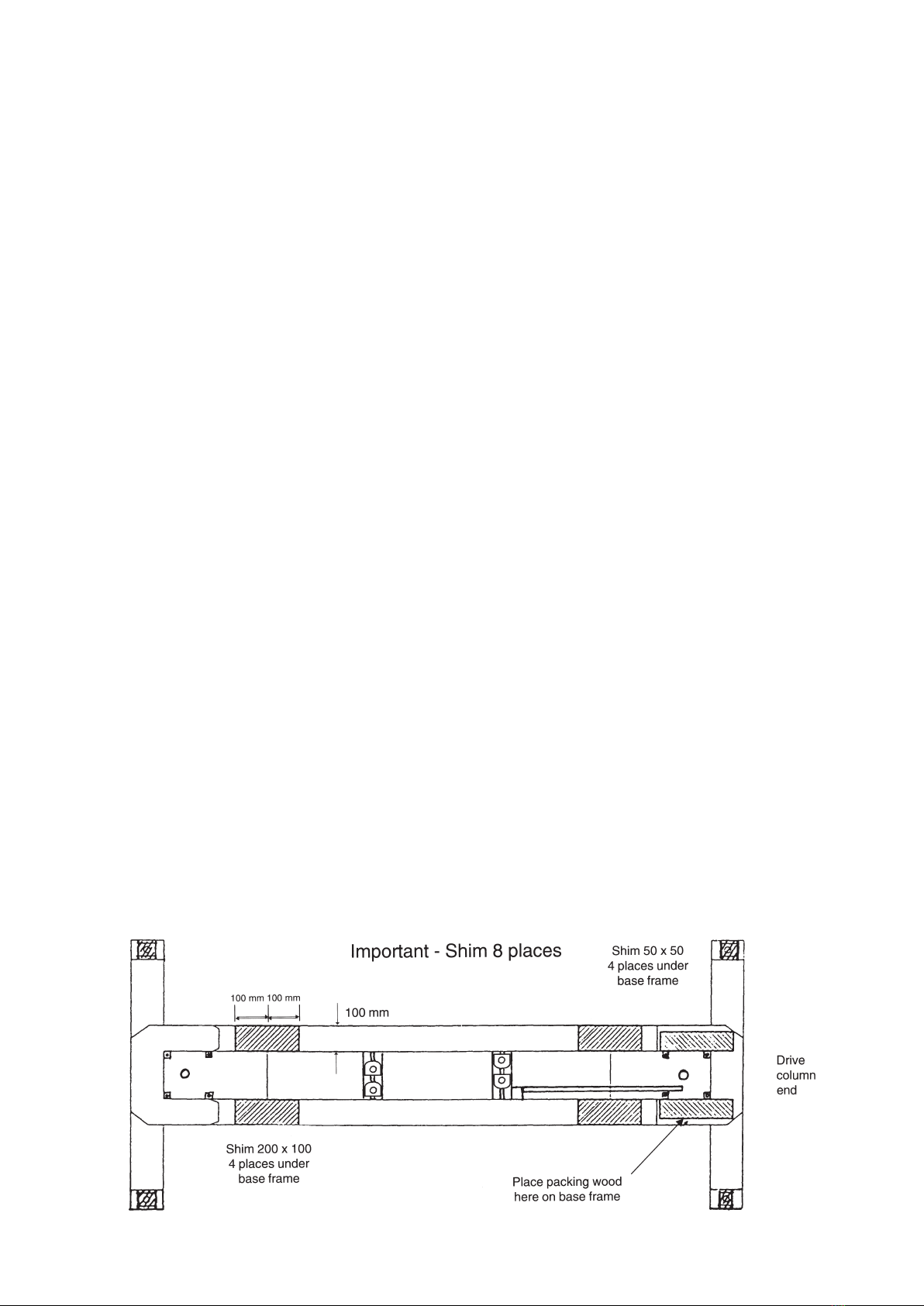
Note: The drive column goes on the end of the base frame that
has the angle iron tted inside (refer Fig.1)
Inspect the oor where the four hold-down bolts will go. The
hold-down bolts must not be installed within 200 mm of any
edge, crack or other fastener in the oor.
4. Level the base frame by adding 50 mm square metal shims,
with a 20 mm diameter hole in the centre, under the base frame
at the four hold-down bolt holes. When level, add 200 x 100 mm
metal shims under the base frame, as shown in Fig.1, to remove
any gap but without lifting the four corners of the base frame o
their shims.
Note: the maximum permissible gap between the base frame
and shims is 0.5 mm.
5. Drill and t four hold-down bolts. The bolts must be 16
mm thread diameter and tted in accordance with the
manufacturer’s instructions:
Approved expanding-type masonry anchors – Ramset Trubolt
T16125 and Hilti HSA stud anchor M16 x 140/25.
Note: The bottom edge of the expansion sleeve on the masonry
anchor must be a minimum of 75mm deep in the concrete when
tightened. If the base has been shimmed up a large amount,
longer anchors will be required to ensure this depth is reached.
Some authorities may not approve expanding type masonry
anchors. Approved adhesive masonry anchors: Ramset Chemset
capsule CHEM 16 and stud bolt M 16190 and Hilti adhesive
cartridge HEAM 16 x 125 and anchor rod HASM 16 x 190.
Note: These fasteners require a minimum concrete thickness
and hole depth of 125 mm.
6. Lay the drive chain in the base frame so that it runs between
the chain rollers as shown in Fig.2.
Note: The joining link spring clip must be on top.
7. At the drive column at the end of the base frame lay two 38
mm thick x 400 mm long pieces of packaging wood along each
leg of the U-shaped plate as shown in Fig.1. Position the drive
column so it is laying on its back (as packed) with the column
base plate on top of the wood.
8. Secure the chain limit switch (which comes out of the bottom
of the column) out of the way, then stand the column up on
the pieces of wood. Position the column so the bolt holes in the
column and base frame roughly line up. Make sure the column
is stable on the wood and is being held at all times to prevent it
falling over.
9. Lay the chain limit switch and wiring in the base frame,
with the wiring lying inside the angle iron and the switch on
its mounting plate as in Fig.2. Reach under the column base
plate and t the chain on to the sprocket (it may be easier if the
column is tilted back slightly). Keep holding the chain tight on
the sprocket. Tilt the column from side to side and remove the
pieces of packing wood (be careful it does not fall).
10. Bolt the column down using two M16 x 50 mm long and
two M10 x 35 mm long high tensile bolts. Leave the M16 bolts
undone about 4 mm (two turns). Fully tighten the M10 bolts
with a ring or socket spanner, then tighten the M16 bolts fully
with a torque wrench to 200NM (147 ft lbs).
Note: The bolts must be high tensile, identied by the marking
‘8.8’ on the head of the bolts.
Fig. 1

4
5
11. Position the block of packing wood at the slave column end
of the base frame, as per Step 7, and stand up the column as per
Step 8. Measure the height of both the drive and slave column
carriages and adjust by rotating the chain sprocket on the slave
column until they are the same height. Move the slave column
toward the drive column about 80 mm and t the chain to the
sprocket. Move the column back again until the chain is tight,
then remove the packing wood as per Step 9.
12. Bolt the slave column down as per Step 10. Measure the
lean on the drive column and the slave column using a plumb
line. Each column should lean outwards between 14 and 26 mm
from top to bottom. Sideways lean should be a maximum of 5
mm o vertical.
13. Tighten the chain by adjusting the four chain guides in the
order shown in Fig.2 until the spring on guide No.4 is just fully
compressed.
Note: to allow the spring to compress, the square locking plate
at the end of the spring must be held vertical by pushing the
top of the plate towards the No.4 chain, guide. Do not over-
tighten the chain, as this will shorten the life of the chain and
guides.
14. Fit the chain limit switch into position, with the limit switch
roller pushing on the plate beside the chain tension spring.
Retain with two M4 x 25 mm long screws. Check the limit switch
roller can still be moved 2 mm to 4 mm clear of the plate before
running out of travel.
15. Apply a smear of grease in the lifting arm pivot holes and the
carriage pivot holes. Fit the lifting arms to the carriages. Fit the
pivot pins and retain with a circlip top and bottom as per Fig.3.
Check the circlips are fully in their grooves.
16. Fit the footguards to the lifting arms as per Fig.3 and tighten
the bolts until the spring is compressed to a length of 46 to 47 mm.
17. Fit the tool trays to 2 of the lifting arms with the M6 x 16
screws and Ø19 x 2 mm thick at washers.
Do the screws up snug tight only, (over tightening will distort
the tray). Check the arms slide in and out freely.
18. Place a lifting pad in the hexagonal hole in each lifting arm.
19. Fit the armlock devices to the carriages and arms as per
Fig.3. Check that the circlips are fully in their grooves and the
Nyloc nut is tightened up fully on the M8 x 55 mm long cap
screw. Lift up on each black knob and check each arm moves
freely through the full arc. Release the knob and check the arm
is locked.
20. Fit the cover over the bottom limit switch and tee piece
using two M6 x 10 mm long socket head cap screws. Fit the
motor cover over the vee belts and secure with the M4 x10 mm
long screw and large at washer.
21. Connect the power supply from the mains isolator switch,
adjacent to the hoist, to the control box on the drive column.
Use the cable gland supplied in the control box to seal the cable
entry in the control box.
Note: This must be done by a qualied electrician.
For a three phase hoist, use 3-core plus earth, 7- strand, 2.5 mm²
copper cable and connect the three active wires to the terminal
strip in the control box. Connect the earth (green) wire to the
earth terminal.
For a single phase hoist, use 2-core plus earth, 7- strand, 4 mm²
copper cable. Connect the active (brown) wire to terminal 1, L1,
on the contactor. (marked K1M). Connect the neutral (blue) wire
to terminal 5, L3 on the contactor. Connect the earth (green)
wire to the earth terminal.
22. Switch on the power to the hoist. Turn the operating switch
to up. The hoist should go up. If it goes down, stop immediately
and turn o the mains isolator, for a three phase hoist, swap two
of the power supply wires at the terminal strip in the control
box. For a single phase hoist, check that the active and neutral
wires have been connected to the correct terminals. Switch the
power back on.
23. Drive the hoist fully up to check operation of the top limit
switch. Drive hoist fully down to check operation of the bottom
limit switch. Swing the four lifting arms in and out with the
lifting pads screwed fully down. If the arms hit the oor in any
position, adjust the arm on the bottom limit switch so the lifting
arms clear. Loosen the chain and try operating the hoist –it must
not operate! Retighten the chain as per Step 13.
24. Apply a liberal amount of oil to the chain and to the slideway
of the spring-loaded chain roller. Fit the drive on ramp and bolt
it down with the M8 x 16 screws and at washers.
25. Drive the hoist up 1 m clear of the oor. Fit a funnel through
the hole in the front blind in the drive column. Pour in a half a
litre of the recommended extreme pressure oil (supplied). Pour
the other half litre into the slave column.
Note: litre of oil will half-ll the oil reservoir in each column.
Do not have the reservoirs more than half full as the excess oil
will be quickly lost.
26. Drive the hoist up and down four or ve times to lubricate
the lifting screws.
The hoist is now ready for operation.
Fig.2 IMPORTANT:
Link must be seen from
the top when installed.
FIG. 3

4
5
Safety Interlock Mechanism
Three Phase Electrical Circuit
Single Phase Electrical Circuit

6
7
Operating Instructions
To raise hoist
Note: read the safety precautions on page 2 before using.
1. Check the hoist arms are clear of the vehicle access area
before driving on.
2. Park the vehicle centrally on the hoist.
3. Position the lifting pads under the vehicle at the pick-up
points approved by the vehicle manufacturer. Adjust the lifting
pad heights to ensure they all lift evenly. Check the lifting arms
and pads will clear the vehicle body, exhaust pipes, etc.
4. Check all personnel are clear of the hoist and vehicle, turn
the isolating switch to the “up” position and raise the vehicle
approximately 500mm, allowing the hoist to take the full weight
of the vehicle. Watch the vehicle while raising.
5. Check that the lifting pads are correctly positioned at the
pick-up points on the vehicle and evenly loaded. Lower the hoist
and re-adjust if necessary. Check the lifting arms are locked into
position. Shake the vehicle to check it is stable.
6. Raise the hoist to the desired height for working on the
vehicle. Watch the vehicle while raising to make sure it will not
collide with anything and stays level and stable.
7. Before commencing work on the vehicle, check the lifting
pads are correctly positioned at the pick-up points and the
lifting arms are locked in position. Lower the hoist and re-adjust
if necessary.
Turn the isolating switch to the horizontal “o” position. This will
stop the hoist and make it safe if there is an electrical fault.
To lower hoist
1. Check the oor area beneath the hoist and vehicle is clear of
people, parts, tools and equipment.
2. Lower the hoist fully. Watch the vehicle while lowering to
make sure it will not collide with anything and stays level and
stable.
3. Move the lifting arms clear of the vehicle before driving the
vehicle o the hoist.
Routine Maintenance
Warning: Always maintain the hoist to keep it safe and reliable.
Daily
1. Lower the hoist to oor level. Check that a gap exists between
lift and safety nuts on both columns.
2. Clean the lifting pads to remove any oil or grease. Inspect
them for any deep cuts or other damage. Replace if damaged.
Monthly
1. Raise the hoist 500 mm. Put a dipstick through the hole in the
column blind down into the oil reservoir. Remove the dipstick
and check the oil level. The oil reservoirs must be kept half-full
(halfway to the bottom of the hole in the blind). Do not overll.
Recommended oils:
Ampol AP80W/90 Caltex Thurban EP80W/90
Esso GX 80W/90 Shell Spirax 80W/90
BP GRXP 15 Castrol HYPOY C80W/90
Mobil Mobilube HD90 Valvoline 18MD 80WD/90
Do not use any other oil or any oil additives.
2. Check the vee belt tension. Individual belt deection must
be less than 10 mm when pressed rmly in mid-span with your
thumb.
Every 3 months
1. Measure the gap between the lift and safety nuts in each
column. If the gap has decreased from the initial setting by 1.5
mm or more, then arrange for the replacement of the lift nut.
2. Remove the base frame ramp and oil the chain. Check and re-
tension as per installation instructions Step 13. if required. If out
of adjustment, shorten the chain on link (remove a maximum of
three links).
Note: use 2 people to lift the ramp.
3. Test the arm locks are moving freely and locking on securely.
4. Grease the top bearings in the columns.
5. Check the operation of the top and bottom limit switches.
6. Lightly oil the arm pivot pins and lifting pad adjusting screws
and other bearing surfaces to allow free movement.
7. Check the footguards are tted and in good condition.
8. Check that all visible bolts and nuts are tight including the
hold down bolts in the oor.
Major Service
Note: use lifting equipment or extra people to lift or handle the
heavy parts.
To Dismantle Column
1. (a) Raise the hoist approximately 1 metre.
(b) Switch o the power at the mains isolating switch, adjacent
to the hoist.
(c) Disconnect cables at the isolating switch (electrician
required) if working on the drive column.
(d) Remove the blind from the column.
(e) Use a suction pump to remove oil from the reservoir.
2. (a) Remove ramp from the base frame and remove arms from
the carriage.
(b) Release chain tension by moving chain guides.
(c) Undo two screws on chain limit switch and remove the
bottom limit switch cover (drive column).
(d) Remove bolts securing base plate of column to base frame.
(e) Slide the column in towards the centre of the base frame
and remove the chain from the sprocket under the column base
plate.
3. (a) Tilt the column back and lower gently to rest on a suitable
support approx. 150 mm high on the oor.
4. (a) At the base of the column, remove the nyloc nut and
withdraw the sprocket from the screw. Remove the key.
(b) Undo the two cap screws that hold the bottom bearing
housing and reservoir in place.
5. (a) At the top of the column, remove the drive cover and vee
belts (drive column only).
(b) Remove the four nuts securing the top plate to the column
(the large pulley may be left in place). Withdraw the top plate
and screw assembly a distance of approximately 500 mm and
place a support under the screw inside the top of the column.
6. (a) Slide the bottom bearing housing o the bottom of the
screw.
(b) Unscrew the lift screw out of the lift and safety nuts in the
carriage. Take care not to damage the screw thread or sealing
surfaces.
(c) Remove the two nuts and the nylon load ring from the
carriage.
(d) Roll the carriage up and out of the top of the column.
FIG. 8

6
7
Inspection Procedure
Lift screw
Thoroughly wash the screw to remove all dirty oil. Inspect the
outside diameter and top and bottom anks of the thread for
any signs of scoring or uneven wear.
Note: The major diameter may have small intermittent grooves
in its outside diameter which are produced during manufacture.
Inspect the bottom sealing surface for damage where the oil
seal runs. Polish out any small scratches with 400 grit emery
paper.
Inspect the bearing areas and keyway for signs of wear.
Lift nut
Wash thoroughly to remove all oil. Inspect the anks of the
thread for signs of scoring or uneven wear. If scored, also check
the lift screw and safety nut.
Inspect the thread minor diameter. When new, it is 2.0 mm thick.
If it is worn to less than 0.5 mm thick, the nut must be replaced.
Check that the trigger moves freely and the spring-loaded pin
slides.
Safety nut
Wash the safety nut and brush to remove all oil. Inspect the
anks of the thread for signs of scoring or wear. Check the
thread minor diameter. When new it is 1.5 mm thick. If it is worn
to less than 1.0 mm thick, the nut must be replaced.
Carriage
Pull the top of the catch bar, at the back of the carriage, 10
mm away from its stop and release it –it must return to its stop
without sticking. Look through the hole in the catch bar pivot
pin. The pin should not be deformed at all –if it is deformed, it
must be replaced. Lubricate the pivot pin and spring guide.
Inspect the four plastic slide pads for wear. There should be no
more than 1 mm wear on the pads. Check the M8 cap screws are
tight. Remove and inspect the bearings in the carriage rollers.
The bearings consist of a layer of bronze particles covered by
a layer of teon. If the bearing appears to be mostly bronze-
coloured, it requires replacement; if it is mostly grey/green
coloured, it is still in good condition. Do not polish o the grey/
green colour on the roller pin unless the pin is scored. Polish
only with 400 grit emery paper and replace the mating bearing
at the same time.
Lightly grease the roller pin, bearing, roller slides and thrust
washers when retting. Make sure the circlips are fully seated in
their grooves.
Bottom bearing
Pull the reservoir tube o the bearing housing. Remove the
O-ring, bearing and oil seal. Wash all parts thoroughly. Inspect
the bearings for any signs of pitting or wear on the balls and
raceways. Fit a new seal and O-ring. Repack the bearing with
grease and ret. Wrap in plastic to keep clean.
Top bearing
Remove the cotter pin and remove the castle nut. Remove the
pulley (or spacer) and the top plate assembly from the screw.
Remove the bearing case from the top plate. Remove the ball
bearing, spacer and inner race of the tapered roller bearing.
Wash all parts thoroughly.
Inspect the bearing rollers and raceways for signs of pitting or
wear. Inspect the domed end of the bearing cage and inside the
top plate for signs of wear. Regrease the bearings and ret to the
case. Grease the outside of the bearing case and t it into the
top plate.
To Re-assemble Column
1. Thoroughly clean the inside of the column where the rollers
and sliders travel, then smear with grease.
2. Ret the carriage and position it about 500 mm up from the
bottom.
3. Check the plastic key covers are still in place in the carriage.
4. Fit the lift nut on to the keys, with the trigger arm through the
hole in the back of the carriage.
5. Fit the load ring between the lift nut and the carriage load bar.
6. Fit the safety nut on to the keys in the carriage, with the brush
towards the front. Leave about a 6 mm gap between the lift and
safety nuts.
7. Carefully t the lift screw to the column and into the lift nut.
Support the top of the screw on a spacer inside the column.
8. Wind the lift screw through the lift nut and safety nut. Check
the gap between the nuts is 6 mm.
9. Fit the reservoir tube over the bottom end of the lift screw
(square end rst).
10. Put some masking tape over the thread and keyway on the
28 mm diameter section. Liberally smear grease over the end
of the screw and masking tape. Carefully t the bottom bearing
housing, seal rst, over the end of the screw and past the
keyway. Make sure the seal is not damaged by the keyway or the
step in the shaft and that the seal spring stays in place.
11. Push the lift screw down through the bottom of the column.
Put some loctite on the two cap screws and bolt the bottom
bearing in place. Fit the reservoir tube on to the bearing
housing, making sure it will clear the carriage when it is lowered.
12. Fit the chain key, sprocket and nyloc nut to the bottom of
the screw.
13. Remove the spacer at the top of the lift screw and t the top
plate and bearing assembly. Fit and tighten the four M16 nuts.
14. Fit the pulley and key (or spacer) and t the castle nut. Do
the castle nut up until the chain sprocket is 6 mm away from the
bottom of the columns. Fit the cotter pin.
15. Tighten the sprocket nyloc nut to 80 Nm torque, push the
carriage down towards the bottom of the column and recheck
the 6 mm gap between the sprocket and the columns.
16. Check the two belt pulleys are aligned, t and tighten the
vee belts to give less than 10 mm deection when pressed
rmly in mid-span with a thumb. Fit the drive cover.
17. Fit the lubricating brush to the front of the safety nut and
adjust it so the bristles are just touching the bottom of the screw
thread. Pour a trickle of extreme pressure gear oil along the
length of the lift screw.
18. Ret the blind. Tighten the two top screws until the blind
springs are fully compressed, then undo them one turn.
19. Measure the height of the carriages on both columns and
adjust them to the same height.
20. The rest of the assembly can be done by following steps 7
to 26 in the installation instructions, with the additional step
of measuring the gap between the lift and safety nuts after
installation is complete. If new nuts have been tted, stamp the
new initial nut gap on the front of the carriage.
Note: This hoist is tted with a special safety interlock which
renders the hoist inoperable should the lift nuts fail completely.
The interlock is tted to both columns and will stall the hoist
approximately 300 mm o the ground.
Operation of the interlock can be checked using gauge G15-1-
51 according to its instructions.

8
9
Problem Symptom Possible Cause Remedy
1. Hoist motor won’t
run.
a. No Noise at all from
motor.
1.No power. a. Check supply for good connection.
b.Check supply fuses.
c.Check operation of isolator switch.
2.Chain tension switch
activated.
a.Tighten chain if loose.
b.Replace chain if broken.
3.Motor overloaded and
thermal overload has cut
power to motor.
a. Wait 5 minutes for circuit to cool and reset overload.
4. Electrical fault. a. Call electrician.
2.Motor runs but hoist
won’t lift.
a.Noise from motor. 1.Vee belts loose. a. Check vee belt tension and adjust as required.
2.Hoist is overloaded. a. Max. weight is 3000kg.
3.Sheared key in either pulley. a. Remove drive cover to see if either pulley turns
without transmitting drive to next section of drive
system.
4.Obstruction encountered
when hoist is lowered.
a. Drive hoist up by inching to clear obstruction.
b. If this fails to work, the bolts securing the base plate
of the column may be loosened by one turn to relieve
the pressure, and then drive the hoist up. The bolts must
then be retightened. This method can only be used when
there is not a vehicle on the hoist.
5. Load nut worn and binding
screw.
a. Replace nuts/ screw.
6. Damaged screw binding on
nuts.
a. Inspect condition of screw and replace screw and nuts.
7. Top bearing incorrectly
assembled.
a. Bearing housing should be removed and bearing
replaced.
8. Interlock engaged. a. Lift nut worn out. Replace as described under ‘Major
Service’.
3. Hoist runs but lacks
power.
a. Hoist appears to run
slow and struggles to lift
light vehicles.
1.Vee belts loose. a. Adjust belt tension, check belts to ensure that they
have not been stretched beyond limit of adjustment.
2. Load nuts tight (get very hot
with use).
a. Inadequate lubrication -oil screw.
b. Check operation of hoist while under load (nuts are all
initially rm but quickly ‘bed in’ with use).
3. Damaged screw which binds
the nuts.
a. Check condition of screw for rough or torn thread.
Replace screw and two nuts as a complete set.
4. Incorrectly assembled top
bearings (housing gets hot
during use).
a. Remove top bearing housing and check assembly
and condition of bearings. Replace bearings and seal if
required.
5. Sprocket binding against
bottom of base plate.
a. Check clearance between sprocket and base plate
using feeler gauges (clearance should be 6 mm).
Clearance is adjusted by turning slotted nut at top of
screw.
6. Motor faulty. a. Check each of phases to ensure all are live.
b. Check supply voltage on each phase.
c. Check continuity of motor windings.
d. Replace motor if required.
b. Hoist stops when lifting
heavy vehicles and will not
restart .
1.Chain is loose. a. Check free operation of slide mechanism on chain
switch guide. Adjust chain tension as per installations,
step 13.
Fault Diagnosis

8
9
Problem Symptom Possible Cause Remedy
c. Hoist stalls when lifting
heavy vehicle.
1.Vehicle too heavy. a. Max. capacity 3000kg.
2. Thermal overload setting
too low.
a. Check setting of overload. Should be 9 amps.
3. Inadequate lubrication of
screw.
a. Oil screws and nuts.
4. Mechanical noise
from:
Carriage
a. Carriage rattles during
travel under no load
condition.
1. Failed bearing in roller giving
rise to excessive clearance.
a. Check each of 4 rollers in the carriage for excess play.
Dismantle column and replace if required.
2. Carriage is bent or
misaligned due to external
damage.
a. Visual check of carriage for damage.
b. Carriage should not be repaired except by Tecalemit
factory. Replace carriage if necessary.
3. Screw is bent causing
carriage to oscillate.
a. This condition will not impair the function of the hoist
unless the screw misalignment is such that it fouls the
load bar and damages the thread.
b. Carriage grates or runs
roughly under load.
1. Failed bearing in a roller
causing rough running.
a. Check each of 4 rollers in the carriage for excess play.
Dismantle column and replace if required.
2. Damaged screw binding on
nuts.
a. Inspect condition of screw and replace screw and nuts.
Drive pulley a. Clattering sound coming
from drive cover.
1. Grub screw retaining motor
pulley is loose, allowing play.
a. Tighten grub screw using Allen key.
Base frame a. Chain noise. 1. Chain not running on guides. a. Set chain to run correctly on the guides and re-tension.
b. Clicking sound. 1. Chain is damaged. a. Check chain for kinking or seized links.
2. Sprocket is loose. a. Inspect sprocket (refer Major Service’).
3. Bottom bearing damaged. a. Inspect bearing (refer ‘Major Service’).
5. Excessive deection
of column under load.
1.Anchor bolts to oor are
loose.
a. Tighten anchor bolts.
2. Bolts securing column to
base frame are loose.
a. Tighten base plate bolts.
3. Insucient support under
base frame.
a. Base frame should be fully supported between
columns, either by the oor or by packing shims. Refer
Installation.
6. Rapid wear on nut. 1. Inadequate or wrong type of
oil used.
a. Rell oil reservoirs with the correct extreme preesure
oil.
7. Hoist does not stop. 1. Switch mechanism spring
return is jammed.
a. Remove red switch handle. Check for oil, grease, dirt
deposits or metal splinters. Clean thoroughly, and ret.
2. Contactor is stuck down. a. Replace contactor.
3.Too much Iubrication. a Dry lift screws. Change oil to recommended oil with no
additives. Fill to the correct level.
b. Check adjustment of brush on safety nut.
4. Lift nuts faulty. a. Replace lift nuts.
Fault Diagnosis continued

10
11
Part No. Description Qty. Item
No.
Part No. Description Qty. Item
No.
1 Phase 3 Phase 1 Phase 3 Phase
V18347 V18655 Drive cover 1 1 V16749 Catch bar 2 48
SMA 1204.10 Screw M4 x 10L cheese hd 1 1a GPS12.65 Spring pin 2 49
WWA1003.10 Washer 3/16” at 1 1b V18653 Reservoir 2 50
CMA006.40 Cotter pin 4 2 V15187 Key 2 51
NWA118.2 Slotted nut 2 3 V18350 V19597 Electric control box 1 52
V18345 V16756 Screw pulley 1 4 V16787 O-ring 2 53
V18342* A950 Vee belt 3 5 SME706.25 Cap Screw M6 x 25 4 54
V18681 V18647 Motor pulley 1 6 V18652 Bottom bearing housing 2 55
GME008.10 Grub screw 1 7 1206 Bearing DRSA 2 56
6206ZCM Bearing DGBB 2 8 V18677 Self-tapping screw 4 57
V17529 Top seat ring 2 9 V18639 Chain sprocket 2 58
HR32206CN Thrust bearing 2 10 NWA1116.6 Nyloc nut 1” BSW thin 2 59
NMA1116.1 Nut M16 x 2 8 11 SME1708.55 Cap screw M8 x 55L 4 60
SME706.50 Cap screw M6 x 50 4 12 NMA1108.6 Nyloc nut M8 4 60a
V16963 Spring 4 13 V18617 All-thread rod 4 61
V18682 V18642 Top plate assembly drive 1 14 V18622 Rod end 4 61a
H161 Hydraulic nipple 2 15 V18620 Spring -oor 4 61b
V18637 Blind mounting 2 16 V18619 Half nut 4 62
V18636 Sealing strip 4 17 V18618 Knob 4 62a
V18635 Aluminum blind 2 18 V16812 Spring 4 63
V19284 V19252 Drive column welded 1 19 V18616 Bearing block 4 64
V19253 Slave column welded 1 20 DIN1400.0360 Circlip 36 mm shaft 8 65
V18643 Top plate assy.slave 1 21 NMA1116.4 Nut M16 thin 4 66
V16750 Key collar 1 22 V19257 Outer arm left 2 67
NMA112.4 NMB110.1 Nut M10 x 1.5 1 23 V19266 Inner arm 4 68
V15153 V18648 Adjusting screw 1 23a V19246 Lifting pad 4 69
NWA1106.1 NUT 3/8 “BSW 4 24 V18662 Pad holder 4 70
28463.8 3/8” sping washer 4 24a V18663 Wire circlip 4 70a
WWA1006 3/8 “ at washer 4 24b V19268 Lift pad bush 4 71
SWA106.10 Screw 3/8 BSW x 1 “L 6 25 V19274 Footguard spring 8 72
V18346 V18646 Motor mounting 1 25a BME1106.60 Bolt M6 x 60L hex. head 8 73
SWA106.12 Screw 3/8 BSW x 1, ”L 4 25b V19264 Arm footguard 4 74
NWA1106.6 Nyloc nut 2 26 V19269 Lift pad assembly 4 75
V18343 V18649 Electric motor 1 27 V18654 Cover 1 76
V16777 Lift screw 2 28 V19258 Outer arm right (not shown) 2 -
V17526 Bearing case 2 29 V20097 Base frame 1 78
V14549 Key 1 30 BME1116.50 Bolt M16 x 50 Grade 8.8 4 79
1201 Seal 4 31 BME1110.35 Bolt M10 x 35 Grade 8.8 4 80
DIN 1460.0280 Circlip 28mm shaft 8 32 V20098 Runway 1 81
V18624 Slide pad 8 33 SME1108.16 Screw M8 x 16L 4 82
SME708.25 Cap screw M8 x 25 16 33a WMA1008 M8 Flat washer 4 83
NMA1108.6 Nyloc nut M8 16 33b SME1706.35 Cap screw M6 x 35L 4 84
V17524 Thrust washer -nylon 16 34 V19231 Chain guide 4 86
V17525 Thrust washer -steel 16 34a V16770 Spring guide 1 87
V16786 Side roller assy 8 35 V14595 Spring 1 88
V19280 Carriage assy. 2 36 V16772 Locking plate 1 89
V16745 Load ring 2 37 V16764 Nut 3 90
V16765 Lift nut & trigger assy 2 38 V18785 T-slide 1 91
V18679 Safety nut 2 39 V17236 Limit switch 3 92
V18656 Lubricator brush 2 40 SMA1404.25 Screw M4 x 25 6 93
SME1706.10 Cap screw M6 x 10 10 41 V17869 Chain & connector link 1 94
DIN1400.0400 Circlip 40 mm shaft 8 42 V19259 Left arm assembly 2 95
V19265 Pivot pin 4 43 V19260 Right arm assembly (not shown) 2 -
GPS05.24 Spring pin 2 44 V17251 Door guard rubber 4 97
V16748 Trigger 2 45 V17659 Key Cover 4 99
V16718 Pin 4 46 V17997 Switch Plate 1 101
V16087 Spring 4 47 V20099 Tool tray 2 102
V16706 Lift Nut 4 47 V16736 Washer M6 x 19 x 2 4 103
SMA1106.16 Screw M6 x 16L 4 104
* Veebelt A x 40 use only cogged belts.
Complete
assembly only.
Refer V16765
Item No.38
10
11
IMPORTANT
TEC 3000X 3 tonne screw hoist
A simple daily visual check will ensure this hoist is
operationally safe
The hoist is operationally safe while a gap exists between the lift
nut and the safety nut.
If the lift nut is allowed to wear to the extent that the two nuts
completely close up, then the safety nut becomes the lifting nut.
This will allow the hoist to be lowered, but a back-up safety
interlock device will prevent further use of the hoist until the lift
nut is replaced.
Daily: Carry out a simple visual check to ensure the nuts have
not completely closed up.
Every 3 months: Measure the gap between the nuts. If it has
decreased by 1.5 mm or more from the initial setting, then
arrange for replacement of the lift nut.
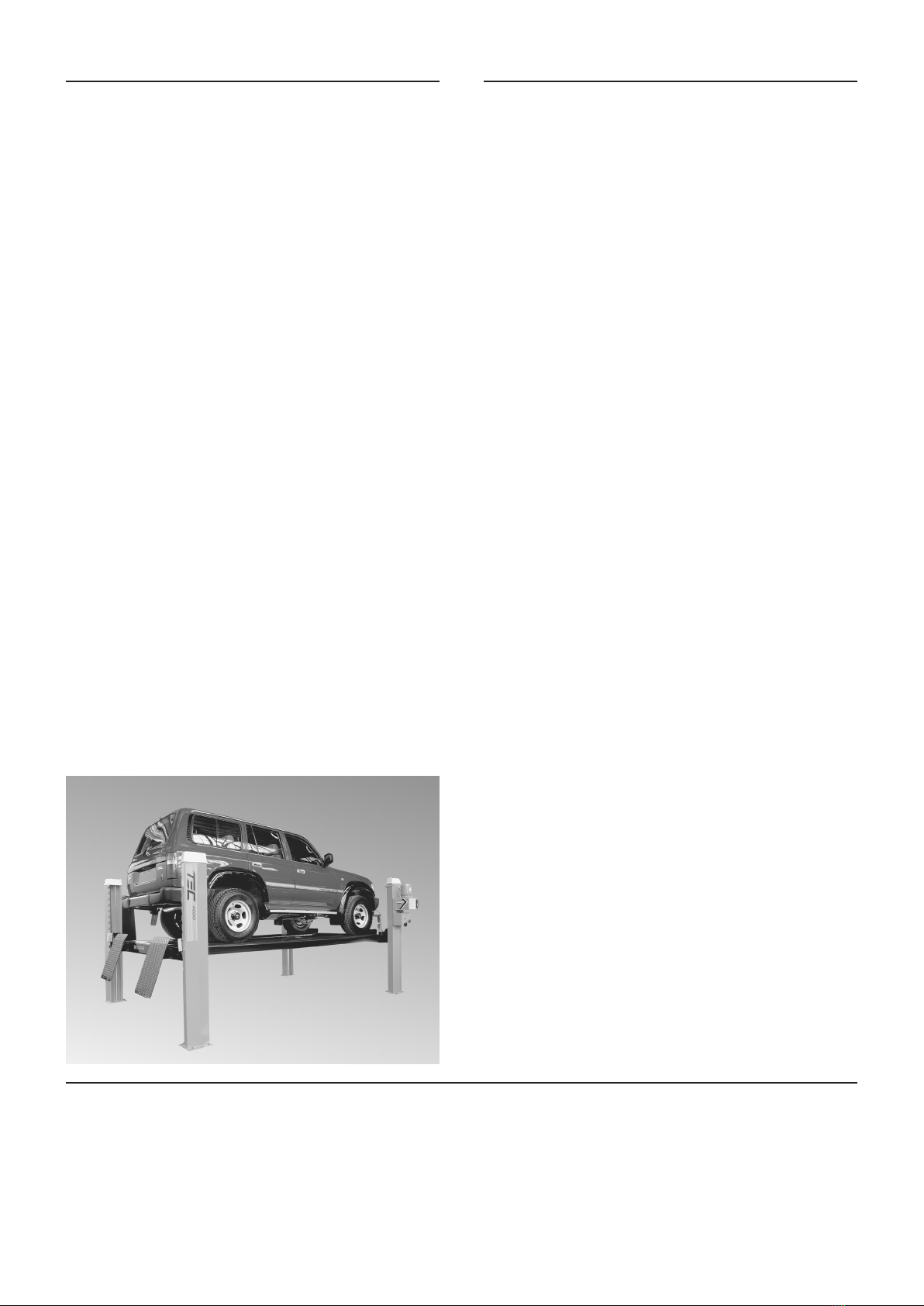
TEC4000 4-Post, 4 Tonne Hoist
Tecalemit Australasia
Adelaide
6 Sheeld Street
Woodville North
South Australia 5012
Phone (08) 8243 5200
Fax (08) 8445 9815
Australia Free Call 1800 685 577
Australia Free Fax 1800 685 533 V20096 Issue 1
Notes:
Other TECALEMIT Lifting System manuals

Popular Lifting System manuals by other brands


stellar labs
stellar labs SHUTTLE 84-12-13 G Assembly and installation manual

Terex
Terex Genie QS-12R Operator's manual

LSP inc.
LSP inc. LSP16H owner's manual

Harmar Mobility
Harmar Mobility HIGHLANDER II Installation & service manual

Terex
Terex Genie Z-45 XC Service and repair manual

Nussbaum
Nussbaum POWER LIFT HF 7000 Operating Manual and Inspection Book


