4
PREPARATION (cont.)
NOTICE: The T-5501 is equipped with a 1/4” NPT air
coupler. If installing a different air coupler, ensure thread
tape or compound is used when servicing connections.
To ensure dependable, trouble free operation an inline air
dryer and oiler is recommended.
5. Pump mechanism should operate smoothly before
putting jack into service. Replace worn or damaged parts
and assemblies with Pro-Lift authorized replacement
parts only.
Bleeding/Venting Trapped Air
With the Release Knob in the OPEN position (step 3b,
pg. 3) and Ram fully lowered, locate and remove the oil
ller screw. As screw is removed, pressurized air may be
heard escaping from the reservoir.
CAUTION: Reservoir may be under pressure and
hydraulic oil may be expelled.
This means trapped air has been successfully removed
from the system. With Lift Pedal in the sleeve, pump 6 to
8 full strokes. This will help release any pressurized air
still trapped within the reservoir. Oil level should be even
with the bottom of the oil ller hole. Reinstall the oil ller
plug/screw.
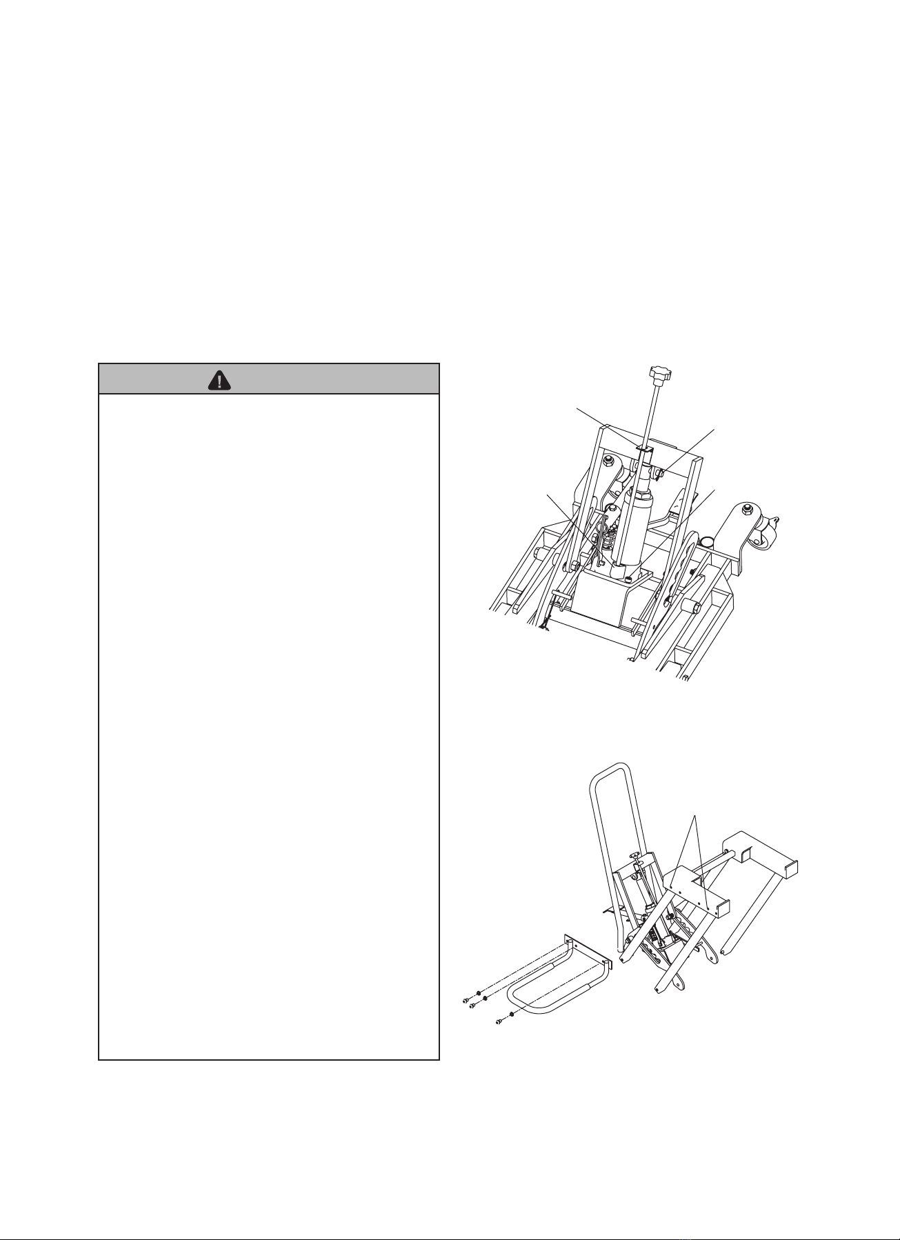
ASSEMBLY
1. Install Hydraulic Unit on receiver and secure with
provided M8 x 1.25 bolts (ref. Figure 2).
2. Insert Ram pin through Ram and Ram brackets on
crosshead assembly, then install cotter pin.
3. Insert Release Knob through Release Knob guide and
attach to Hydraulic Unit with screw and nut provided.
4. Insert Lift Pedal into Sleeve and attach with supplied
bolt.
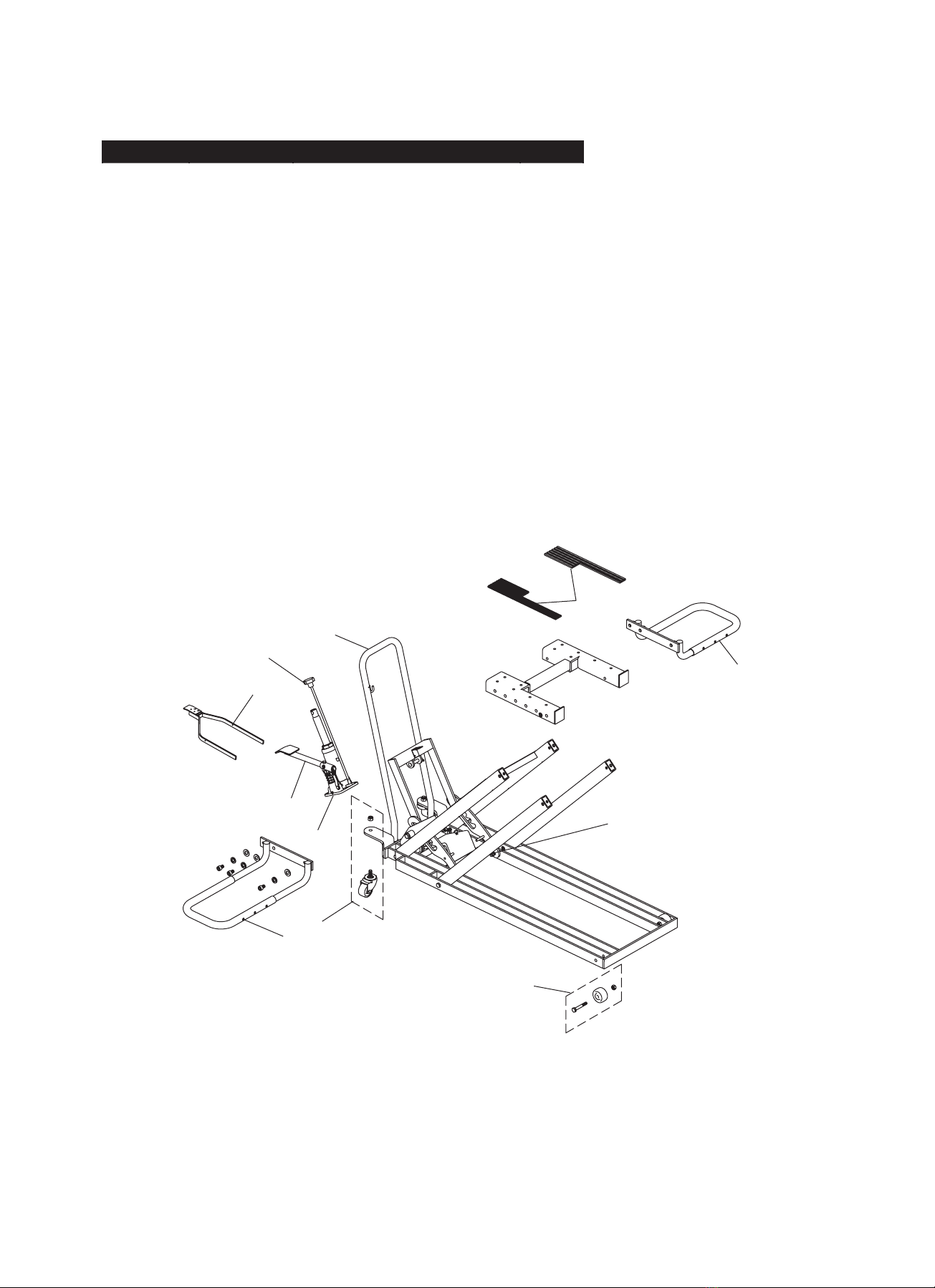
5. Install Positioning Handle into frame and secure using
the provided pins (2).
6. Attach two Wheel Brackets to sides of Lift Platform (ref.
Figure 3).
7. After assembly, ensure that lift rolls, lifts and locks,
and that pump operates smoothly before putting into
service. Familiarize yourself with how Height Locking
Lever, Lift Pedal, and the Height Unlocking Lever
operate prior to loading lift. Replace worn or damaged
parts and assemblies with authorized replacement
parts only (ref. Replacement Parts, pg. 6). Lubricate
as instructed in Maintenance Section.
OPERATION
1. Adjust Wheel Bracket width for mower track.
2. Drive mower onto Wheel Brackets.
WARNING: Use only on hard, level surfaces capable
of sustaining rated capacity loads.
3. Leave mower transmission in neutral, close Hydraulic
Release Valve and carefully pump jack until mower
reaches desired height. Final height must correspond
with the locking teeth on the Height Locking Lever.
4. Carefully turn the Release Knob counterclockwise until
the Lift Platform engages the Height Locking Lever,
then close the Release Knob by turning it fully clock-
wise. Do not work around or under load unless Height
Locking Lever is properly engaged.
5. Secure the mower by setting the parking brake, putting
transmission in gear and chocking the wheels.
CAUTION: Clear all tools and personnel before
lowering load. Only attachments and/or adapters
supplied by the manufacturer shall be used with this
device.
6. To lower the Lift Platform, release the mower’s parking
brake, place transmission in neutral and remove
chocks. Pump the Lift Pedal several times to disengage
the Height Locking Lever, then depress the Height
Unlocking Lever pedal. Carefully turn the Release
Knob counterclockwise to lower the load slowly.
MAINTENANCE
Keep lift clean and well lubricated. Apply a couple of
drops of light machine oil to all pivoting joints as needed.
Thoroughly wipe up excess oil.
NOTICE: Use premium quality hydraulic jack oil. Avoid
mixing different types of uid and NEVER use brake
uid, turbine oil, transmission uid, motor oil or glycerin.
Improper fluid can cause failure of the jack and the
potential for sudden and immediate loss of load.
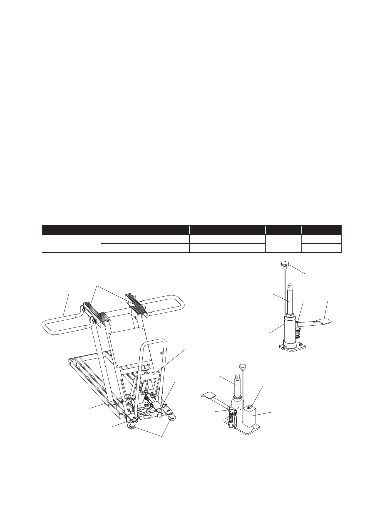
Adding oil
1. To check hydraulic oil level, unload lift, lower Lift
Platform completely, then remove Hydraulic Unit from
lift. Place Hydraulic Unit upright on a stable, level
surface. Locate and remove Oil Filler Plug.
2. Ensure the oil level is even with the Oil Filler Plug hole.
Reinstall the Oil Filler Plug, then install Hydraulic Unit
onto receiver. Secure with provided bolts.
Changing oil
For best performance and longest life, completely replace
the hydraulic uid supply at least once per year.
1. With Lift Platform fully lowered, remove Hydraulic Unit
from lift. Place Hydraulic Unit upright on a stable, level
surface. Remove the Oil Filler Plug.