Affordable Wheelchair Lifts KCSPM3648 User manual
AFFORDABLE WHEELCHAIR LIFTS

_____________________________________________________________________________________
SAFETY
Safety is paramount. If you have a question or concern about safe
installation or operation please give Affordable Wheelchair Lifts
a call at (757) 524-3420
Use common sense when installing or operating this equipment.
The installer and operator are responsible for the safe operation of this
equipment.
It is your responsibility to know and comply with all applicable
legal codes and regulations regarding your wheelchair lift.
Misuse of this equipment can cause serious injury or even death.
WARRANTY WARNING
Do not open any control boxes, motors, or hand control devices. The
product warranty will be void if these components are tampered
with. Do not attempt to alter component wiring or adjust or
modify the structure of the product in any way or the warranty
will be void. Any repair or replacement of wheelchair lift parts
must be performed by authorized personnel.
LUBRICATION
This product is designed to be maintenance free. The lift motors are
permanently lubricated and sealed – no additional lubrication is
required. The anti-friction pads need no lubrication.
Note: Throughout this document this is used as a caution symbol:
_____________________________________________________________________________________
_____________________________________________________________________________________
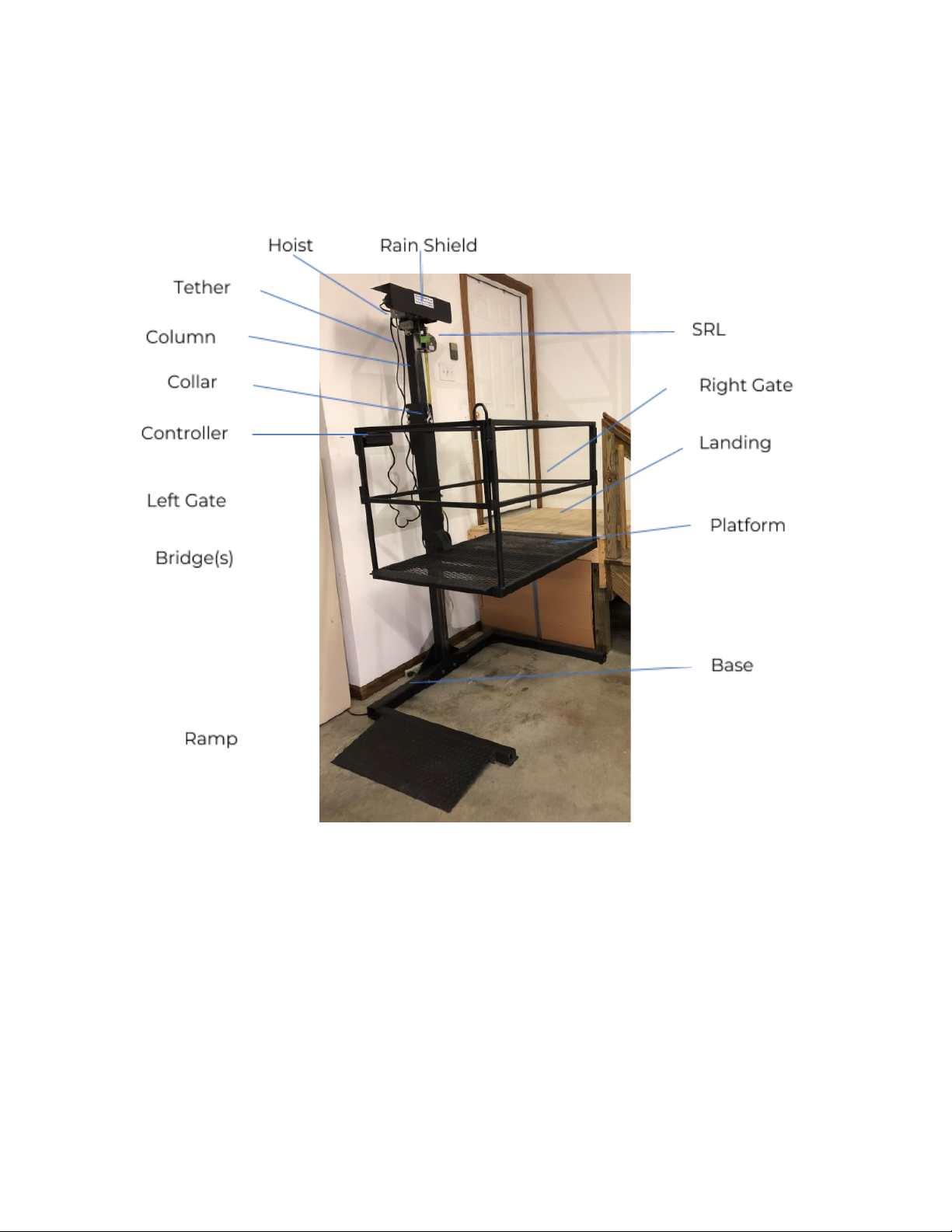
Lift Components Illustration
This photo might not exactly match your particular lift.
ORIENTATION
Front, Back, Right and Left - The Column is located on the back side
of the lift. The side of the lift opposite the back is the front. Right
and left are determined when you outside of the lift facing it
from the front.
_____________________________________________________________________________________

_____________________________________________________________________________________
Lift Components Table
Base
U-Shaped bars that support the entire unit.
Platform
The platform is the metal, gated enclosure that
carries the passenger up and down
Gate(s)
A removable and reversible gate is attached to each
side of the platform. Each gate has a latch.
Bridge(s)
A bridge is the flat diamond plate metal surface
attached to each side of the platform.
Column
The column supports the hoist and the
Self-Retracting Line (SRL)
Landing
The level area from which you enter and exit the lift
platform when the platform is at its designated rise
height.
Collar
The collar attaches to the platform and slides up
and down the column. A safety guard covers the
collar.
Hoist
The hoist raises and lowers the platform. AC and
DC powered hoists are available. In exterior
applications, a rain shield protects the hoist from
weather.
Controller
The controller houses the Up and Down switches
for the lift.
Ramp
This is an optional diamond plate metal surface to
provide a smooth entrance to the platform.
Rain Shield
The rain shield keeps rain from the hoist motor.
Tether
Connect the controller to the hoist.
SRL (Self-Retracting
Line)
Serves as a safety backup in case the lifting
mechanism fails.
_____________________________________________________________________________________

_____________________________________________________________________________________
Introduction
Congratulation on your purchase of a new wheelchair lift from Affordable
Wheelchair Lifts! This lift has been quality engineered with design
features to assure safety and reliability then installed and operated
properly. We sincerely hope that this lift will help you accomplish the
things that are important to you and those you love.
This manual is designed to help guide you in the safe and secure
installation of your new wheelchair lift. This manual covers only the
installation of a fully assembled unit. You may wish to also consult
the Owner’s Manual and the Assembly Instructions.
NOTE: If your new wheelchair lift arrived unassembled and crated, as is
common for general freight carrier delivery, please refer to the
Assembly Manual to properly assemble the unit before proceeding
with the instructions in this manual.
Excerpt from the Order Confirmation Email:
The customer understands that he/she is responsible for this wheelchair lift's proper
and safe installation and operation. This includes but is not limited to:
●Making sure the lift is installed in a safe location by personnel adequate to the
task.
●Making sure that the electrical power is adequate and supplied in a safe
manner. Outdoor and garage lifts need to use a GFI circuit.
●Making sure the lift and its installation complies with any applicable
regulations and that any lift operators are properly trained.
●Recognizing that Affordable Wheelchair Lifts' delivery technicians will deliver
the lift and are not necessarily qualified or licensed to do related electrical,
masonry, carpentry or other contractor type work.
●Addressing any applicable taxes.
●Inspecting the lift periodically to insure that it is safe to operate.
Regarding lift operators and users, the customer understands
that:
●The customer is responsible for making sure that the person(s) operating the
lift has/have been instructed in its use pursuant to the Owner's Manual and
are mentally capable of safely operating the lift.
●This may mean restricting access to the lift controller(s) to prevent unqualified
persons from operating the lift.
_____________________________________________________________________________________

_____________________________________________________________________________________
●Persons with dementia or who are susceptible to mental confusion are not
qualified to operate the lift, though a qualified caregiver may operate it for
them.
●Persons incapable of recognizing that the lift has reached ground level are
not qualified to operate the lift, though a qualified caregiver may operate it
for them.
●The manufacturer is not responsible for injuries or damages of any sort
resulting from operator error.
Planning Your Installation
While installation circumstances, such as indoor versus outdoor, can require
some common-sense tweaks to your lift installation, most all of the
steps and considerations outlined here apply to any lift installation.
First, the installation site should be flat and level, free of debris and as
accessible as possible. The lift should sit on a solid surface (ground
floor, concrete, asphalt, etc.) or substantial pavers
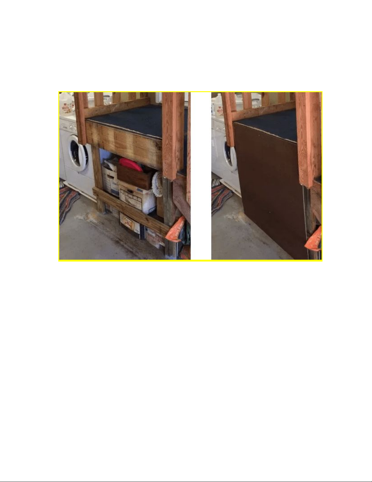
The landing area also should be flat and level. Any needed modifications to
landing railings such as cutting away a railing section or installing a
railing safety gate should be made prior to or during installation. Toe
shear protection should already be installed.
_____________________________________________________________________________________
_____________________________________________________________________________________
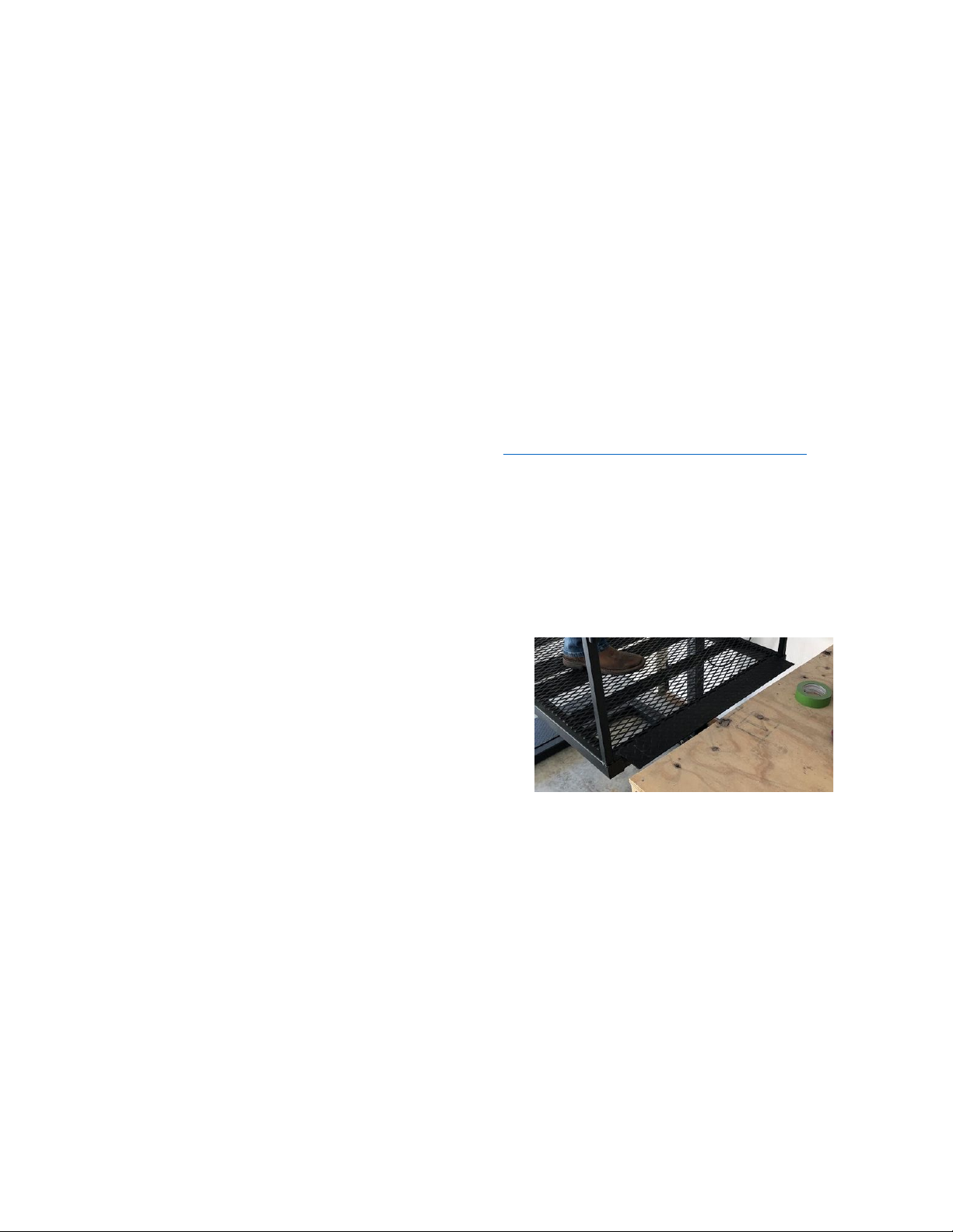
Toe shear protection should be installed if it has not already been done.
Before Toe Sheer Protection With Toe Sheer Protection
Children and pets should be excluded from the area during installation.
The amount of electrical power needed to run the lift depends upon which
hoist motor you have chosen. Most require 15 amps. GFI circuits
should be used where appropriate.
Most customers prefer the lift be oriented for straight-through travel from the
ramp onto the Platform to the landing to inside the home (or onto the
second floor). Sometimes this is not practical.
If your lift is equipped with multiple wireless control buttons, be aware these
devices work over a 50-foot radius. Someone with a wireless controller
who is out of sight of the lift can activate it. Always unplug your lift before
cleaning or maintaining it to prevent someone inadvertently using a call
button to activate the lift and accidently causing injury or death.
_____________________________________________________________________________________
_____________________________________________________________________________________
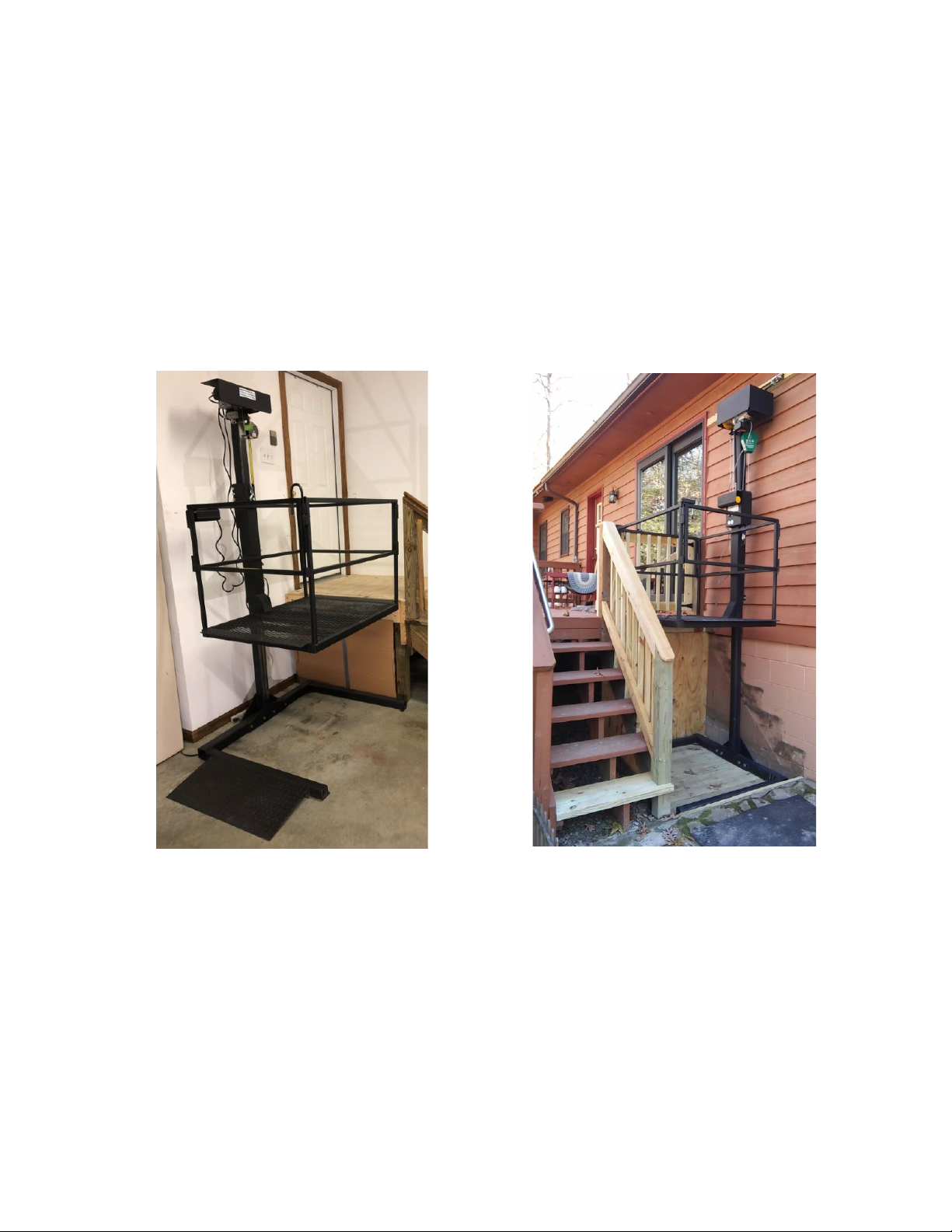
We recommend that, if possible, the Column side of the lift be placed closest to
a nearby wall. If bracing is desired (or required) then this positioning will
make bracing easier. Generally speaking, your lift will not require bracing
if it is rising to a landing of 48 inches or less in height, although you may
desire bracing for added stability. For lifts traveling over 6 foot or to a
second floor (96 inches or more), we would suggest bracing is mandatory.
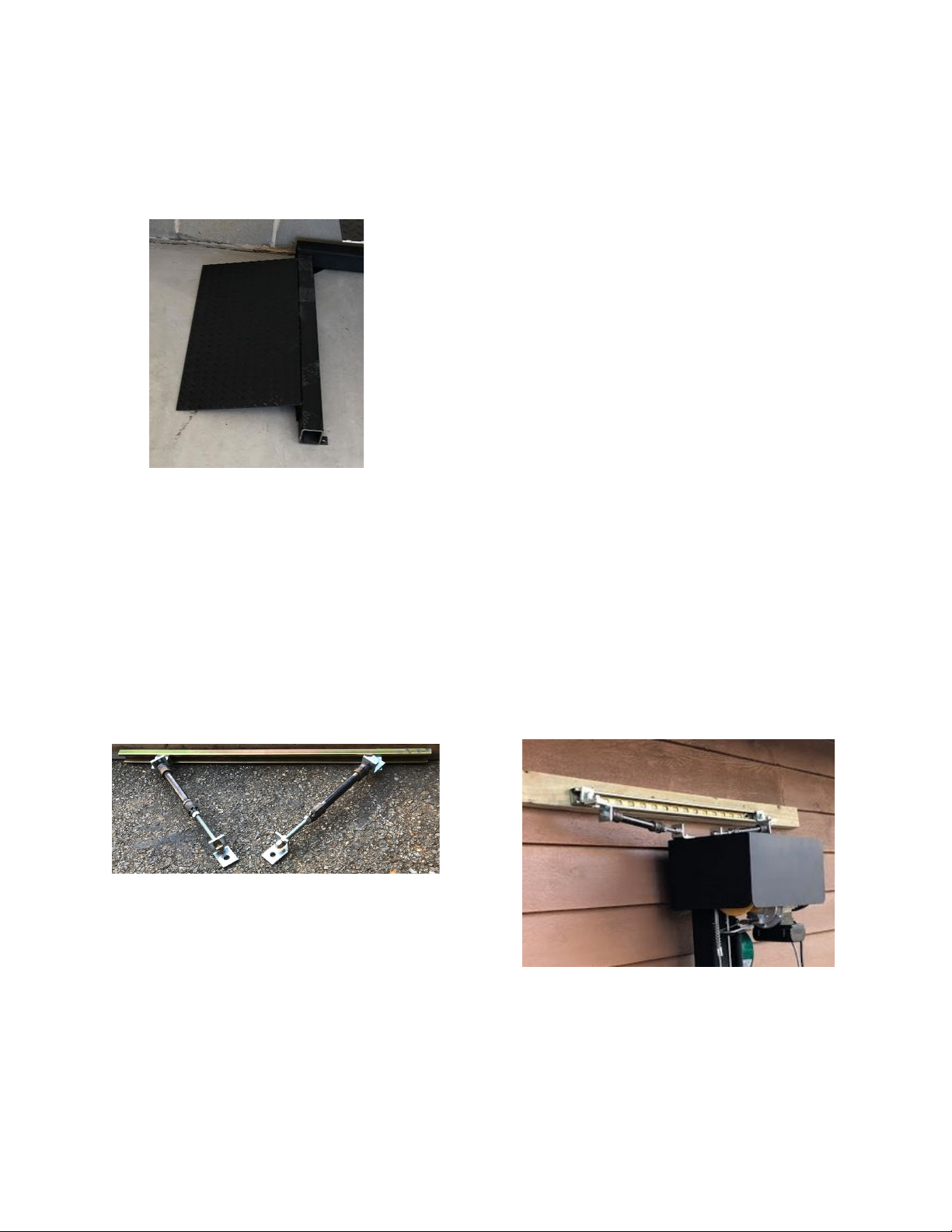
The following two photos demonstrate two different “lift platform-to-landing”
orientations, as well as an unbraced (left photo) and a braced (right
photo) installation, as evidence by the brace bar above the rain shield.
_____________________________________________________________________________________

_____________________________________________________________________________________
Gates (Re-positioning)
Each gate comes pre-attached to the Platform. While gate and latch styles may
vary, each gate can hinge on either the right or the left side of the
Platform. The default is to hinge on the left side when entering the
Platform from either direction.
This gate is hinged on the left side.
You can detach a gate easily and switch the
side it hinges from using the appropriate
wrenches or sockets.
To change the hinge side for a gate, remove
the two bolts and lock-nuts to detach the
gate. Position the gate hinges the way you
want them, then re-insert and fasten the bolts
to re-attach the gate.
Rehinge each gate, as needed, to best suit
your particular installation site.
Positioning Your Lift
The Lift can be moved with a dolly or a crowbar and some good
old-fashioned muscle. For positioning the lift in a tight space, it might
be helpful to invest in some detachable wheels for moving the
platform base. (Contact Affordable Wheelchair Lifts for wheels.)
Regardless of your method, it’s time to move
your lift to its final position. Don’t worry about
leveling or bracing the unit just yet. We’ll cover
that later.
First, we want to adjust the unit’s positioning
relative to the landing and set the lift’s
maximum platform height.
Once we have the lift in its desired position, slowly raise the platform to the
height of the landing. The goal here is to accomplish two things. First,
we want the want the edge of the Bridge to be around ¼” from the
toe shear board all along the Platform’s travel, and especially at the
landing. Reposition the lift accordingly.
_____________________________________________________________________________________
_____________________________________________________________________________________
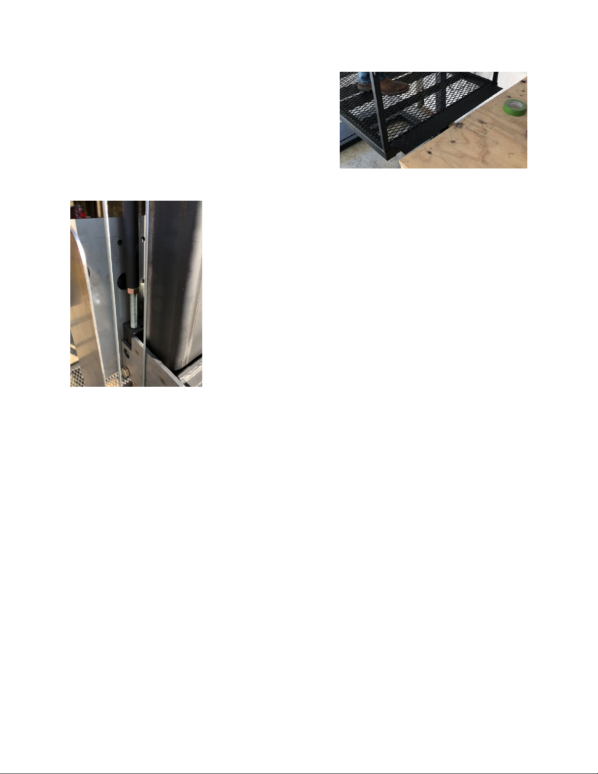
Secondly, we want to set the maximum
Platform height for the lift – the
height level with your landing. This
adjustment is made by raising or
lowering the nut on the metal rod of
the Limit Switch Actuator. (See
Below)
This metal rod, nut and accompanying plastic tubing is
located behind the Safety Guard and all adjustments can
be made without removing the Safety Guard. The metal
rod can just slide out once you remove the plastic rod.
With the plastic rod seated on the metal rod, carefully use
the controller to raise the platform until the limit switch
stops it. Measure your current Platform height. Then do
one of the following steps. (Repeat this process until the
Platform stops at the height you desire.)
If the Platform stops at your desired height, then tighten the nuts to each other to
prevent them from moving. You have now completed the step of adjusting the lift’s
maximum height.
If the Platform stops lower than you want, then shorten the limit switch
actuator to allow the Platform to go higher:
●Determine how many inches higher you want the Platform to actually go.
●Lower the platform a bit to give you some slack to work with.
●(You can do the steps below without removing the Safety Guard. The metal
rod can just slide out once you remove the plastic rod.)
●Shorten the limit switch actuator by the number of needed inches by
lowering the nuts on the metal rod.
●Do not lower the nuts any lower than 2” from the lower end of the metal rod,
or the rod will not be stable it its slot.
●If you cannot lower the nuts enough you can always easily cut the plastic rod
with a knife or saw to be slightly shorter. Do not accidentally cut the plastic
rod too short or else you will need to either replace the plastic rod or purchase
a longer metal rod.
_____________________________________________________________________________________
_____________________________________________________________________________________
If the Platform stops higher than you want, then lengthen the limit switch
actuator to force the Platform to stop lower:
●Determine how many inches lower you want the Platform to actually go.
●Lower the platform a bit to give you some slack to work with.
●(You can do the steps below without removing the Safety Guard. The metal
rod can just slide out once you remove the plastic rod.)
●Lengthen the limit switch actuator by the number of needed inches by raising
the nuts on the metal rod.
●Do not raise the nuts any higher than 2” from the upper end of the metal rod,
or the upper rod will not be stable on the lower rod.
●If you cannot raise the nuts enough you can always replace the plastic rod
with a longer one. The upper rod is simply 1” diameter EMT pipe that can be
bought at any hardware store and easily cut to a different length. It is pressure
fitted onto the trigger plate, so you can easily attach the trigger mechanism to
your new pipe. (If your lift arrived assembled and did not include assembly
instructions, please visit our website at www.affordablewheelchairlifts.com for
additional information.)
Leveling Your Lift
Use a level and shims to shim the base so that the lift is level. The most critical
point to adjust the leveling is between the edge of the Bridge of the
Platform and the landing.
_____________________________________________________________________________________
_____________________________________________________________________________________
Position the Entry Ramp
The ramp sits on the floor (ground) next to one of the base arms.
A “U” shaped metal connector can optionally be
used to keep the ramp from moving over time.
This connector rests on its back with one of its
arms on the inside of the base’s arm and the
other of its arms on the inside of the ramp’s back.
Brace Your Lift
Bracing is required for lifts with more than 4’ of rise. We can supply the
bracing kit, or you can make your own. Wall mounted lifts and lifts of
more than 6’ require a bracket cap to support more robust bracing.
Affordable Wheelchair Lifts sells a bracing kit that is customized for your
situation. Contact us.
_____________________________________________________________________________________

_____________________________________________________________________________________
Anchoring Your Lift (Optional)
Anchoring your lift to the floor or to a concrete pad is optional. There are
four anchor points built in to the lift base should you desire to anchor
your lift.
Do not anchor the lift down until you are sure of the final lift locations.
Make sure the gates are properly working, the unit is level and
interacting with the landing railings first!
Drilling Note - If you are securing your lift to a concrete pad (or garage
floor), then drill deep enough so that the anchor can be hammered
down into the pad (floor) once the lift is removed.
_____________________________________________________________________________________

_____________________________________________________________________________________
AFFORDABLE WHEELCHAIR LIFTS
Installation Manual
© Affordable Wheelchair Lifts
2884 Hidden Lake Drive
Williamsburg, Virginia 23185-8020
Phone (757) 524-3420 • Fax 708.253.1632
www.AffordableWheelchairLifts.com
_____________________________________________________________________________________
Other manuals for KCSPM3648
2
Table of contents
Other Affordable Wheelchair Lifts Lifting System manuals


Popular Lifting System manuals by other brands

Genie
Genie Z-51/30J operators manual with maintenance information

AMGO Hydraulics
AMGO Hydraulics MRL09 Installation and service manual

Ricon
Ricon UNI-lite Service manual

Berg Hortimotive
Berg Hortimotive BeNomic Star 300 Technical manual

MoJack
MoJack HDL 45501 Instructions for assembly and operation

Mobilex
Mobilex DS2176 user manual


AMGO
AMGO 408-P Installation and service manual

TECHNOLIFT
TECHNOLIFT SL-12 Installation, operation & maintenance manual

JLG
JLG 4108AN Operation and safety manual

MetalTech
MetalTech PJ-PJST OPERATIONAL SAFETY AND ASSEMBLY INSTRUCTIONS

Joerns
Joerns Quickfit Deluxe Sling user guide

pela tools
pela tools SF-C4000MS manual