TERRY Lifestyle 3.6m User manual
Model 3.6m
User Manual
Original instructions

CONTENTS
Introduction 3
Description 4
General Do’s and Don’ts 5
Controls and operation 7
Smoke alarms 9
Emergency procedures 11
Fault finding 19
Changing smoke alarm batteries 21
Changing call station batteries 22
Safety feature check 23
Service history record 24
Declaration of conformity 25
Lift specification sheet 26
2

3
INTRODUCTION
Thank you for choosing the Lifestyle Lift, designed and
manufactured in the U.K. using the latest technology by Terry
Group Ltd. We want you to get the most out of your Lifestyle Lift
and to help in this aim we have produced this small booklet on
operation and maintenance of the equipment, which we hope you
will find helpful.
It is hoped that any queries you may have during day to day
operation will be answered in the text, but if you do have any
problems, technical assistance is only a phone call away.
We hope our product gives you many years of reliable service.
Peter Morrey
Managing Director

4
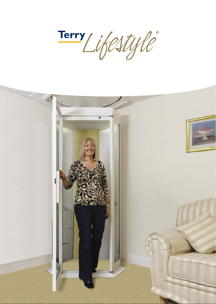
DESCRIPTION
The Lifestyle Lift is an inter floor lift that is designed for use by up
to two people standing or one person seated travelling between
fixed floor levels in private dwellings.
With a maximum carrying capacity of 250kg, this lift is not
intended for use as a means of transporting goods.
The lift is designed to operate without a lift shaft and is provided
with an automatic infill panel which makes the ceiling aperture
safe when the lift is parked downstairs.
Optional GPRS two way communications or a hard wired
standard telephone can be supplied in the car for emergency
communication.
A standard feature is the provision of half hour fire rated panels in
both the aperture infill and the car underpan.
The lift car panels are made from powder coated steel which can
easily be cleaned using normal household cleaners. Upholstery
is made from high quality contract materials and can be cleaned
in the same way.

GENERAL DO’S AND DON’TS
• Never switch off the power supply to the lift, even when you go
away. The lift control circuits are fed by a battery, which must be
kept on constant charge.
• The lift should always be returned to the lower level when
not in use. If it is left upstairs for prolonged periods, it will
occasionally re-level itself depending on conditions. The lift must
be left at the lower level if the mains is turned off.
• Keep hold of the door whether opening or closing.
• Always close the door after using the lift.
• Never allow children to play in, under or around the lift. If
children are in the house, always isolate the lift using the
optional remote control fob, see page 7.
• Ensure that the area under the lift is kept clear. The underpan
surface is fitted with sensors, which automatically stop the lift if it
strikes an object (see pg.6).
• Always keep the key fob, if supplied and emergency release
key in a safe place near the lift. The in-car release keys behind
the centre cover should not be removed unless there is an
emergency.
• Do not place any object on the aperture infill or stand on it when
the lift is in operation. Ensure that as far as practical, the area
around the travelling infill panel is clear of persons (particularly
children) when the lift is being operated. The infill panel is fitted
with sensors that automatically stop the lift if the infill panel is
obstructed (see pg.6)
• Only use the lift for transporting up to 2 people standing
or 1 seated between fixed floor levels. Do not use for the
transortation of goods.
• Always treat your lift with the respect that should be shown to
electrical and mechanical equipment.
• Safety related components should only be adjusted and reset
by a competent person.
5
Table of contents
Other TERRY Lifting System manuals


Popular Lifting System manuals by other brands

probst
probst SDH-H-15 operating instructions

Bruno
Bruno OUTDOOR ELITE CRE-2110E Operator's manual

matev
matev FPS Mounting Assembly Installation Guide

Vestil
Vestil CYL-HLT Series instruction manual

Butts Tools
Butts Tools BXS0002 operating instructions

Safelift
Safelift MoveAround MA60 Original instructions


R. Beck Maschinenbau
R. Beck Maschinenbau HS 600 operating manual

Nova Technology International, LLC
Nova Technology International, LLC NAS Series quick start guide

Genie
Genie Z-60/34 Operator's manual

Screen Technics
Screen Technics INTERFIT Vertical Up Lift instructions

Drive
Drive DUPONT SAMERY Hermes user manual

Custom Equipment
Custom Equipment Hy-Brid 3 Series MAINTENANCE & TROUBLESHOOTING MANUAL