AfiMilk AfiPass II User manual

For Technicians | AfiPass II Installation Guide
Release Date | January 27, 2021
AfiPass II
Installation
Guide

For Technicians | AfiPass II Installation Guide

For Technicians | AfiPass II Installation Guide
Table of Contents
About this Guide and Scope ..................................................................................................................1
Intended Users .....................................................................................................................................1
Conventions..........................................................................................................................................1
Safety ...................................................................................................................................................1
High Power Safety Precautions..............................................................................................................2
1Introduction ............................................................................................................................. 3
1.1 Principle and Flow of Operation ...................................................................................................3
2Prerequisite Considerations...................................................................................................... 4
2.1 General .......................................................................................................................................4
Software................................................................................................................................................................. 4
Electrical Requirements ......................................................................................................................................... 4
Environmental Specifications................................................................................................................................. 4
ID Tag Requirements.............................................................................................................................................. 4
2.2 Parlor Electrical Grid - Grounding Requirements ...........................................................................4
3Ordering Components .............................................................................................................. 5
3.1 Ordering AfiPass II Controller System ...........................................................................................5
3.2 Ordering Antenna........................................................................................................................5
3.3 Sourcing Antenna Brackets ..........................................................................................................7
3.4 Ordering Transformers (Requirements) ........................................................................................7
3.5 Ordering Replacements Parts.......................................................................................................8
4Understanding Installation Workflow ....................................................................................... 9
5Mounting the Components....................................................................................................... 9
5.1 Mounting the Antennas .............................................................................................................10
Positioning the Antenna....................................................................................................................................... 11
Positioning the Brackets....................................................................................................................................... 12
Attaching the Brackets ......................................................................................................................................... 15
5.2 Mounting the AfiPass II Controller..............................................................................................16
AfiPass II Controllers – Mounting Locations ........................................................................................................ 16
5.3 Mounting Process ......................................................................................................................19

For Technicians | AfiPass II Installation Guide
6Laying the Cables.................................................................................................................... 20
7Wiring the System .................................................................................................................. 22
7.1 Grounding the System ...............................................................................................................22
7.2 Wiring Device #1........................................................................................................................22
7.3 Inserting Cables into the AfiPass II Controller..............................................................................22
7.4 Wiring the Cables to the Connectors ..........................................................................................24
AfiPass II Control PCB Layout ............................................................................................................................... 25
AfiPass II Control PCB Connections...................................................................................................................... 25
Connectors and Functions ................................................................................................................................... 27
7.5 Finalizing the Wiring Connections...............................................................................................31
8Setting AfiPass II Addresses and Calibrating Antennas............................................................. 32
8.1 Opening Test Mode ...................................................................................................................33
8.2 Setting Device Addresses ...........................................................................................................34
8.3 Calibrating the Antennas............................................................................................................35
8.4 Setting Transmission Power and Reception Range ......................................................................36
8.5 Testing ID Range and Troubleshooting........................................................................................38
8.6 Returning to Work Mode ...........................................................................................................39
9Configuring the System........................................................................................................... 40
10 Using AfiPass - First Time ........................................................................................................ 42
10.1 Gates Indicators.........................................................................................................................43
11 Identifying Faults and Troubleshooting ................................................................................... 44
APPENDIX 1 ................................................................................................................................ 45
Cable Chain for Vertical Lift Chest Bar Stall Work .................................................................................45
Cable Chain Length Calculations ..........................................................................................................45
APPENDIX 2 – DIP Switch ............................................................................................................ 47
Contacting Technical Support, Help Desk .............................................................................................49
Legal Notice........................................................................................................................................49
Certification................................................................................................................................ 50

1
For Technicians | AfiPass II Installation Guide
About this Guide and Scope
This guide describes the pre-installation, installation, startup and troubleshooting procedures for
AfiPass II.
AfiPass II is the next generation ISO ID system, integrated inside Afimilk systems. This new system
substitutes the previous – AfiPass I ID system.
Intended Users
This guide is intended for Afimilk™ dealers’ technicians and qualified personnel.
Conventions
Warning: Actions requiring special attention to avoid serious physical injury. For example,
working with high voltage components.
Caution: Actions requiring special attention, to avoid possible damage to equipment or
livestock.
Note: Recommendations for working efficiently.
Safety
Warning: Do not dispose of WEEE as unsorted municipal waste!
•Read this manual carefully. Proper handling of the equipment is the basis for correct
functioning.
•The AfiPass II device is installed and tested at the milking parlor by a qualified technician
authorized by Afimilk.
•The customer is fully responsible for any changes made, either in the system configuration or
in the software application data, by the customer or by the customer’s agent.
•Afimilk will not be held responsible directly or indirectly for any damage caused to the
customer and/or to a third party and/or to the animals, by an action and/or change and/or
omission performed in the AfiPass II system and/or in the milking device, either by the
customer or by the customer’s agent, directly and/or indirectly.
•Afimilk recommends that the customer call for a full system inspection by a qualified
technician authorized by Afimilk every six months.
•The device is intended for indoor installation only.
•It is the user's responsibility to install, operate, and maintain the system in accordance with
all applicable codes, regulations, and safety measures.
•Any person installing and operating AfiPass II must be authorized to do so, after receiving
appropriate training for proper usage of the machine and equipment and all related risks.
•Never install AfiPass II if you are not sufficiently authorized and trained to do so, nor allow it
to be used by unauthorized persons.

2
For Technicians | AfiPass II Installation Guide
•Do not flush the electrical or electronic equipment with water or any other liquid.
•It is the responsibility of the operator to operate and maintain the system in accordance to all
applicable local codes, regulations, by-laws, and safety regulations.
•Disconnect power before servicing.
High Power Safety Precautions
•High voltage transients, surges, and lightning can cause extensive damage to equipment,
people and livestock. It is the installer's responsibility to provide a power protection system
to protect the system from these and other power irregularities.
•Make sure that all electrical connections, including grounding of the metal structure, are
properly performed by a qualified electrician.
•Compliance with FCC standards is conditional upon the system being installed in accordance
with the formations in which the product passed the standards tests, and the declarations
given to the authorities. Any changes or combination made in the system, other than those
defined, will not be approved by the standards and is referred to accordingly.
•Operate the system under conditions that comply with the declaration of conformity, the
T.C.F., and the test reports in these documents.
•The transformer should be UL/CSA certified.
•The transformer is not provided with the equipment. Installation shall be performed by a
certified electrician in accordance with the National Electric Code (NEC) and local codes. It is
the responsibility of the installer that equipment be powered from an external UL/CSA
certified transformer of appropriate rating.

3
For Technicians | AfiPass II Installation Guide
1Introduction
AfiPass II™ is an ISO (Passive) identification system integrated into the AfiFarm herd management
system. AfiPass II is based on the principle of radio frequency identification (RFID) and refers to
automatic identification of animals using ISO 11874/5 compatible passive ID tags (without batteries).
AfiPass II supports a per stall ID system and walk through ID systems per the configurations officially
released by Afimilk. AfiPass II supports the following setups:
•Parlor stall ID - per the defined models of:
Herringbone,
Parallel.
Note: Sort gates based on AfiPass II will be released soon.
Note: Until specifically announced, AfiPass II may NOT be installed in Rotary Parlors.
1.1 Principle and Flow of Operation
The AfiPass II system communication steps are:
1. The AfiPass II Controller sends an ID request signal via an antenna.
2. The ID request signal energizes a transponder in an identification tag.
3. The identification tag responds with a unique ID number back to the antenna.
4. The antenna receives the tag transmission and relays it back to the AfiPass II Controller.
5. The AfiPass II Controller relays the tag ID number to the AfiFarm herd management system.
6. AfiFarm uses the ID number for controlling AfiFarm stations and for data collection - herd
management.

4
For Technicians | AfiPass II Installation Guide
2Prerequisite Considerations
2.1 General
Software
AfiPass II is only compatible with AfiFarm 5.4 and above.
Electrical Requirements
Designation
Requirement
Rated Voltage
24 VAC Nominal (single phase)
Input Voltage Range
20.4-27.6 VAC
Rated Frequency Range
50/60 Hz
Input Current Range
0.7-1.5 Amp AC
Max Power Consumption
36 VA
Environmental Specifications
Designation
Requirement
Temperature
Operation: -20º to +50º C (-4º to +122º F)
Storage: -40º to +85º C (-40º to +185 º F)
Humidity
Operation: up to 80% RH without condensation
Storage: up to 85% RH without condensation
ID Tag Requirements
All cows on the farm must have their tags attached to the ear on the same side. This is important for
establishing the location of the antennas.
AfiPass II supports ISO standard HDX passive ID tag types (ISO 11784/5).
2.2 Parlor Electrical Grid - Grounding Requirements
•Potential difference between ground and zero: ≤~0.6V
•Spike: ≤~0.9V
5
For Technicians | AfiPass II Installation Guide
3Ordering Components
The equipment listed here refers to the AfiPass II ID system alone, not including other products
required for the full Afimilk system, communications etc.
The equipment for ordering includes:
•AfiPass II controllers – per parlor size.
•AfiPass II antennas – per number of ID stalls and type of metal works.
•Other equipment required (may be sourced separately or locally).
3.1 Ordering AfiPass II Controller System
The number of AfiPass II Controllers required is determined by the number of ID stalls in the milking
parlor.
Each device supports up to 5 stall antennas. Therefore, multiple AfiPass II Controllers are required to
set-up a full milking parlor. All the Controllers are connected on a single daisy chain communication
line, connected at the AfiFarm PC via its communication devices (AFiCom USB).
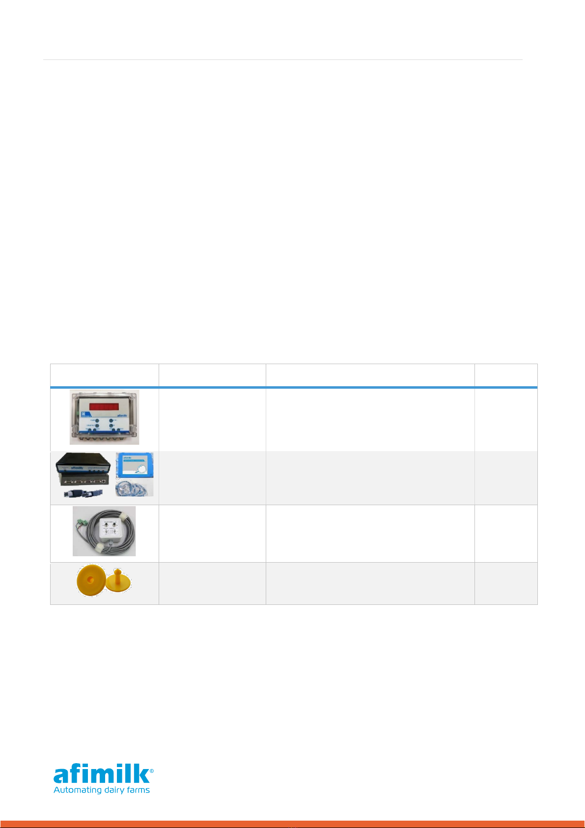
Table 1 – AfiPass II System Components
Picture
Name
Description
P/N
AfiPass II Controller
Assembly
Operates up to 5 antennas.
Parlor gates may be connected to the
controller.
4095910
AfiCom USB4
Adapter Assembly
This may have already been ordered with
the milk meters. If so, it is not necessary
to re-order.
4193030
AfiPass II Technician
Tool
This tool is required for installing the
AfiPass II system. It should be part of the
toolbox of Afimilk installers.
4095921
ID tags
Cow Ear Tag - HDX only
May be sourced locally.
3.2 Ordering Antenna
The AfiPass II antenna is a plastic rectangle. Each milking stall requires an individual antenna, which
is mounted onto structures within the parlor (such as metal frames, or parlor walls).
For best results, the antenna should be mounted as close as possible to the cow's head, and as close
as possible to the ID tag (the ear carrying the tag). However, it should also be mounted far enough
from neighboring cows to avoid ID mistakes.
6
For Technicians | AfiPass II Installation Guide
Before ordering antenna, conduct a survey of the site to determine which antenna type best suits
the parlor (see Table 2). Selecting the antenna type will also need to take into consideration optimal
mounting locations (see Chapter 5.1):
Table 2 – Selecting AfiPass II Stall External Module 50 or 40
AfiPass II Stall External Module 50
AfiPass II Stall External Module 40
The 50 cm antenna has a larger range; hence
when there is enough space and the distance
between the stalls is larger it should be used.
The 40 cm antenna should be used when there
is not enough space to install the 50 cm
antenna.
Mostly suitable for wall mounts and feeding
troughs. Mostly suitable for rapid exit parlors.
The 40 cm antenna should be used when the
distance between the stalls is small or lack
separation, and there is a risk the larger antenna
may interfere with antenna on next stall, or may
read the tags on the cows in the neighboring
stalls, or the cows finished milking and
transferring through the exit passage.
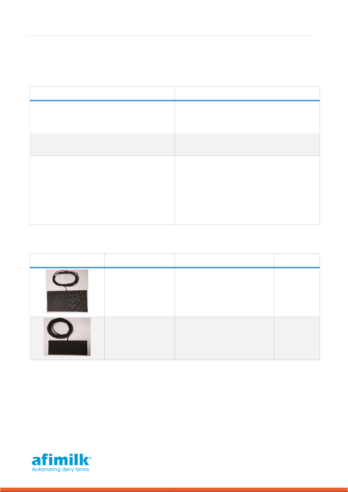
Table 3 – AfiPass II Antenna
Picture
Name
Description
P/N
AfiPass II Stall
External Module 50
A 50 cm X 26 cm air loop passive
antenna prewired with 15 m
coaxial cable. Ferule type
terminals included.
4095912
AfiPass II Stall
External Module 40
A 40 cm X 14.5 cm air loop
passive antenna prewired with
15 m coaxial cable. Ferule type
terminals included.
4095914

7
For Technicians | AfiPass II Installation Guide
3.3 Sourcing Antenna Brackets
The antennas are mounted in the stalls using brackets that are designed and built to suit both the
antenna size and the location where it will be mounted.
Custom made brackets are available for the most common parlor types. These are manufactured
and sold directly from relevant companies.
Note: Custom-made brackets Antenna are available in the US market for the most common
parlor types and are sold directly from relevant companies. Contact your local Afimilk
representative for details.
Note: All brackets are the dealer's responsibility to source (including manufacture and
purchase), according to our guidelines. For further details, contact Afimilk support.
3.4 Ordering Transformers (Requirements)
The AfiPass II system requires an isolating transformer that supplies power only to the AfiPass II
Controllers. The size of this transformer depends on the number of controllers it powers.
Caution: The transformer must be supplied with suitable circuit breakers.
The AfiPass II Controller uses up to 36VA during transmission (ID request) and 19VA during idle
operation.
Controllers on the same side of the parlor will never transmit simultaneously, while Controllers on
opposite sides might. Therefore, we recommend installing transformers on each side of the parlor to
power the Controllers on that side.
To calculate the power requirements for each transformer, use the following formula:
= +( − ); where:
•P = the transformer's required power rating in VA (Volt Amper)
•N = The number of controllers used.
For example: To power three devices a transformer with a power rating of = + ∗ =
should be used.
Transformer power rating [VA]
Number of devices allowed
75
3
100
4
200
9

8
For Technicians | AfiPass II Installation Guide
Table 4 - Transformer
Picture
Name
Description
P/N
Power transformer
230/24 -27 VAC OR 110/24 VAC.
May be sourced locally.
5009401
3.5 Ordering Replacements Parts
The following can be ordered as required:
Table 5 – Ordering Replacements
Picture
Name
Description
P/N
Rubber Stoppers
Secures the AfiPass II
Controller lid while open.
2 units in a package. 5001768
Grommets for
replacement
(Each grommet has 3
inlets.)
5 Green units - for 6.5 mm (~¼″)
cables. 5001764
2 Blue units - for 7.0 mm (~¼″)
cables. 5001763
Grommet nuts for
replacement 7 units in a package. 9020726

9
For Technicians | AfiPass II Installation Guide
4Understanding Installation Workflow
Lay the cables (see Chapter 6).
Wire the system (see Chapter 7).
First time use (see Chapter 10).
Mount the devices (see Chapter 5).
Set Device Addresses and Antenna Calibration
(see Chapter 8).
Configure AfiPass II in AfiControl (see Chapter 9).
10
For Technicians | AfiPass II Installation Guide
5Mounting the Components
Mount the AfiPass II components according to the steps below.
5.1 Mounting the Antennas
Confirm the environment provides an option to mount the antenna, where the cables and antenna
are protected from animals and surrounding elements (such as constant exposure to water/steam).
Note: Special consideration must be made to protecting the cables from animal licking and
chewing. We recommend ducting the cables within the stall work itself.
Before mounting the antenna, consider the following:
•The ear (left or right) on which the tags are located.
•The Stall type, size (specifically – the stall width), and structure.
•The location of the cow's head within the stall, and any movement restrictions to the cow's
head while in the stall.
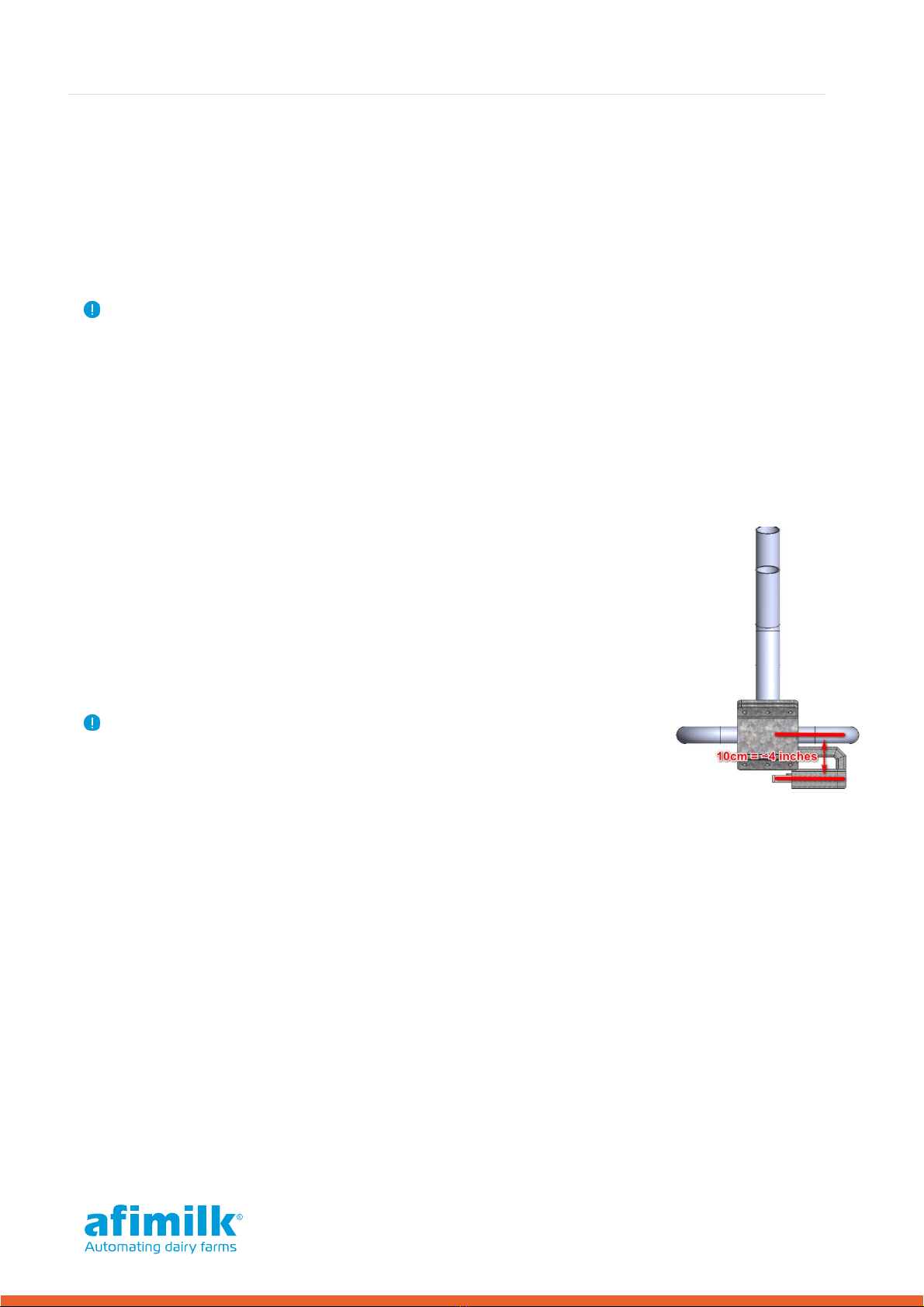
•The presence of metal loops, which substantially decrease the
antenna's ID coverage. Antenna should not be mounted closer than 10
cm (in parallel) to any closed metal loops or plates in the parlor
construction and metal works. Open structures (such as "U"-shaped) or
perpendicular loops don’t affect the range.
•Existing structures within the stall (for example, feeding troughs, chest
bars, neck rail, overhead bars, walls).
Note: See Chapter 5 for examples of brackets on which to mount the
antenna, and various mounting solutions for different parlor setups.
The antenna location and position varies according to the parlor type, metal works, Breast rail type,
and position. Consequently, each mounting procedure depends on the current setup of the parlor.

11
For Technicians | AfiPass II Installation Guide
Positioning the Antenna
The antenna ID range can be controlled by changing the antenna orientation or adjusting the
antenna transmission power.
Each side of the antenna projects a different range, as illustrated in Figure 1:
•A– illustrates the range projected from the front and back of the antenna.
•B– illustrates the range projected from the sides of the antenna.
•C– illustrates the range projected from the top and bottom of the antenna.
Figure 1 – Antenna ID Range (Side and Front Views)
Antenna range is adjustable via the AfiPass II Controller (see Chapter 8.4). Increasing the
transmission power increases the ID range on each side of the antenna. In turn, this increases the
distance available for the antenna to successfully detect the ID Tag. (However, it may also increase
the risk of detecting incorrect tags of neighboring cows.)
Table 6 below illustrates how increasing the antenna transmission power increases the range
projected on each side of the antenna. Table 6 also compares the different ranges available for the
50 cm and 40 cm antennas.
Table 6 – Antenna ID Coverage Range for ISO ID Ear Tags
Antenna
Transmission Power
Side A
Side B
Side C
50 cm
Antenna
40 cm
Antenna
50 cm
Antenna
40 cm
Antenna
50 cm
Antenna
40 cm
Antenna
Minimum Range
25-30 cm
(10"-12")
20-25 cm
(8"-10")
16-22 cm
(6"-9")
15-20 cm
(6"-8")
12-16 cm
(5"-6")
10-14 cm
(4"-6")
Medium Range
55-60 cm
(22"-24")
50-55 cm
(20"-22")
35-40 cm
(14"-16")
30-35 cm
(12"-14")
28-32 cm
(11"-13")
26-30 cm
(10"-12")
Maximum Range
75-85 cm
(30"-33")
65-70 cm
(26"-28")
45-50 cm
(18"-20")
40-45 cm
(16"-18")
38-44 cm
(15"-17")
34-38 cm
(13"-15")

12
For Technicians | AfiPass II Installation Guide
Positioning the Brackets
The parlor setup affects the antenna position and brackets required for installing the antennas.
The examples below provide a range
of bracket design and installation
locations to suit various parlor
setups.
Example 1: Parallel Neck Rail
If installing the antenna in a parlor
that utilizes a neck rail, use the 40 cm
antenna. The brackets must fasten
the antenna using mounting
solutions that accommodate the type
of neck rail and pole profile.
Antenna Location
The top of the antenna should sit 110
– 120 cm (43"-48") above the floor, depending on the cow's height. The top of the antenna should
align 2.5 – 5 cm (1"-2") above the ear height.
Bracket Design and Attachment
Figure 2 - Parallel Neck Rail – Bracket Dimensions
13
For Technicians | AfiPass II Installation Guide
Front View
Side View
Top View
Note: In vertical lift rapid exit solutions, special consideration must be given to protecting the
antenna cables from bending when the rail is lifted/lowered during operation, and from
contact with the cows, see APPENDIX 1 for solutions to this.
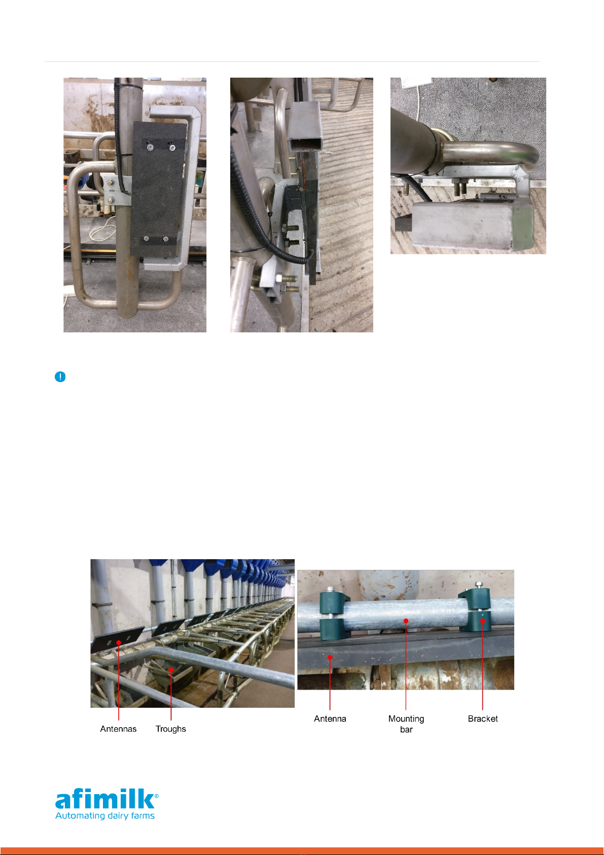
Example 2: Overhead Mounting in Parallel Parlor with Wall Mounted Feeders
The example below illustrates brackets attached to a bar that runs across the top of the feeding
troughs.
Antenna Location
The antennas are mounted as close as possible to the troughs, so that the ear tags come into range
of the correct antenna while the cow eats from the trough.
Bracket Attachment
14
For Technicians | AfiPass II Installation Guide
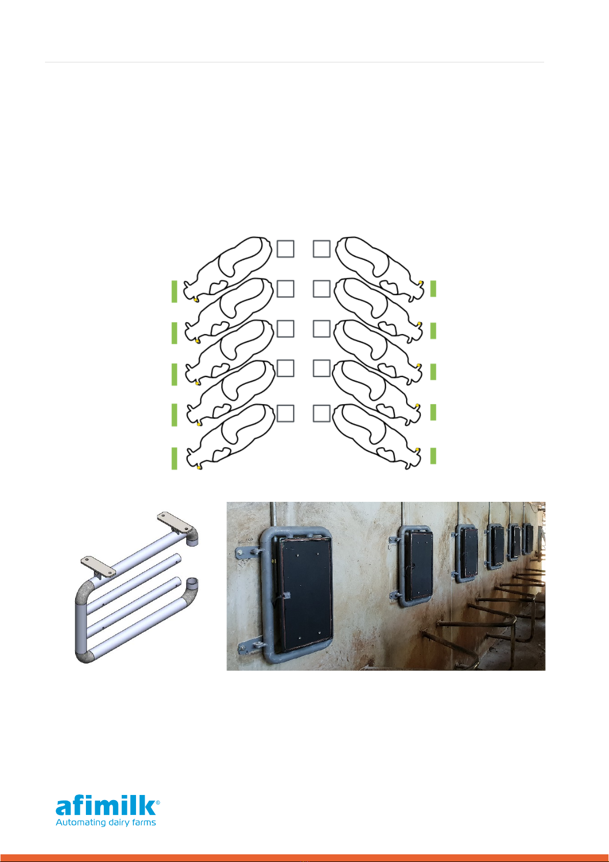
Example 3: Herringbone (with/without Feed) without Rapid Exit
In straight line parlors (with no Rapid Exit), side walls can be used for mounting the antennas in front
of the cows' heads, so they are centered to the ears with the tags.
The antenna type and distance depend on the height of the cows and the side of the parlor they're
located on.
On the parlor side where the ear tag sits further from the wall (See cows on the left side in the image
at right), it may be advisable to use the 50 cm antenna to achieve a wider range. We also
recommend using the 50 cm antenna in parlors without feeders and/or when there is constraining
metal works below the cow's chest.
50 cm Antenna Bracket Design and Attachment for Wall Mounting
Herringbone Parlor – 50 cm antenna mounted on the wall.
15
For Technicians | AfiPass II Installation Guide
40cm Antenna Bracket Design and Attachment for Wall Mounting
There are examples where it may be appropriate to use the 40 cm antennas on a wall mounting. If
these antennas are used, position them at the cow's head height
Herringbone Parlor – 40 cm antenna mounted on the wall.
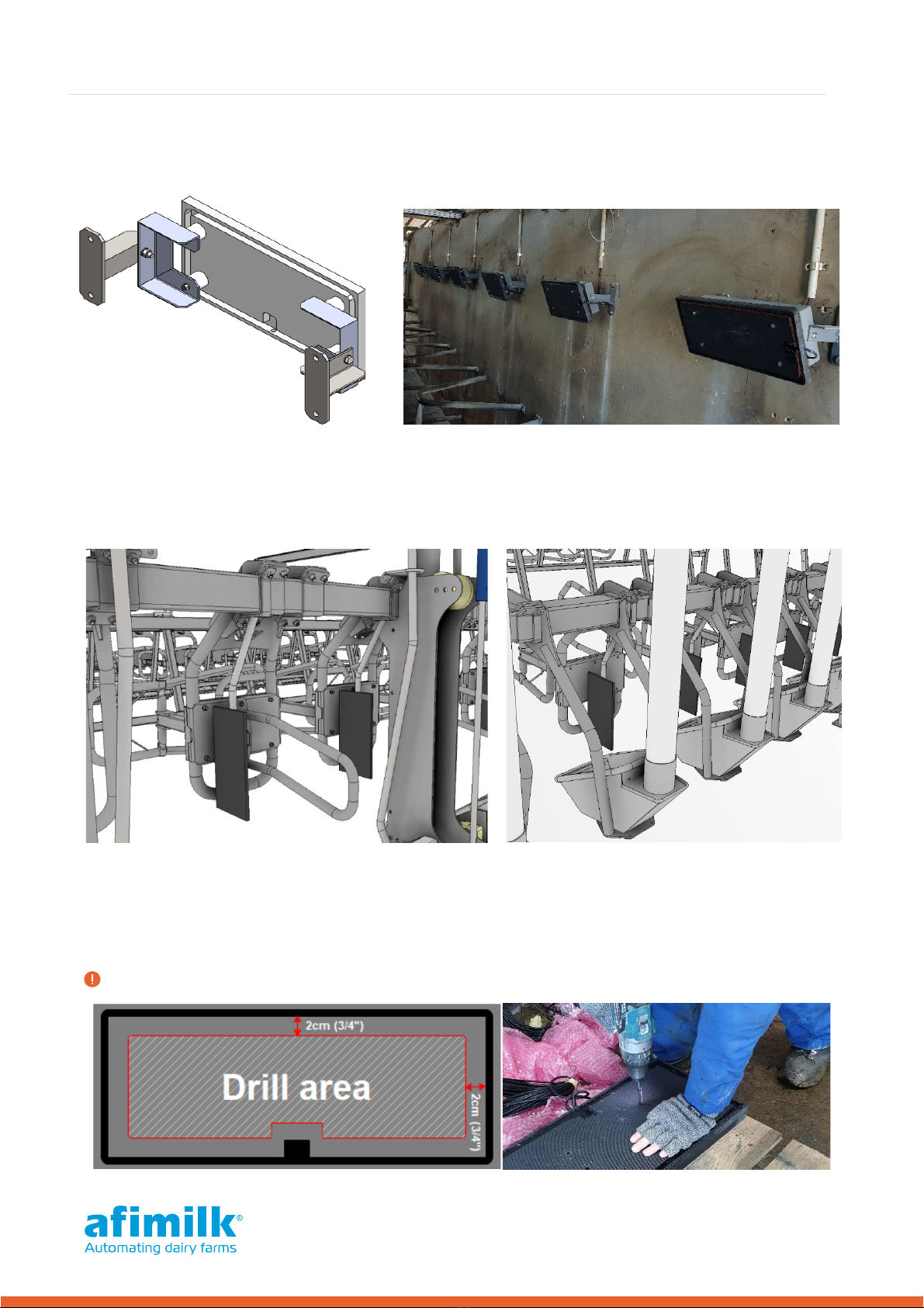
Example 4: Parlors with/without Feeders
The images below illustrate alternative antenna location options.
Attaching the Brackets
Attaching the antennas to the brackets may require the technician to drill into the antenna plate. To
avoid damaging the antenna, be very careful to only drill through the allowed section.
Warning: Drill only within the drill area as shown below.

16
For Technicians | AfiPass II Installation Guide
5.2 Mounting the AfiPass II Controller
Choose appropriate mounting locations for the AfiPass II Controllers. The locations should meet the
following conditions:
•Mounting stability - the AfiPass II devices require a stable structure (such as a wall or
overhead beam) on which to mount.
•AfiPass II & Communication to PC - communication lines can be extended up to 350-
400 meters (383 – 437.5 yards).
•Electrical interference - Place the AfiPass II Controller and the antenna cables as far as
possible from electric power lines or other electrical disturbances (especially from AC
controllers, AC motors and Main power cables) to avoid electrical interference.
AfiPass II Controllers – Mounting Locations
The AfiPass II Controllers are mounted in the parlor as follows:
One controller is mounted in the middle, between the two parlor sides. This will act as
Device #1 (Main Display Device). Device #1 must be visible from the milking pit (to monitor
the ID and gate status).
•The rest of the controllers are mounted according the number of milking stalls on each side.
Device sequencing is based on sets of 5 antennas connected to each device, beginning from
stall #1 which must be connected to Device #1 (Main Display Device). See mounting examples
below.
Note: Regardless of which side of the parlor you choose to install the Main device, when your
back is to the Main device, your left-hand side should always point to the 'low' stall numbers.
This will ensure the corresponding entry/exit LEDs are on the correct side of the Main Device
display.
Table of contents
Popular Controllers manuals by other brands


Johnson Controls
Johnson Controls VA-9070 Series manual

Contemporary Research
Contemporary Research ICC-ZS2 product manual

Rinnai
Rinnai MC-601 Operation & installation manual

Leroy-Somer
Leroy-Somer R438 Installation and Maintenance

Ruckus Wireless
Ruckus Wireless ZoneDirector 5000 Getting started guide

ABB
ABB ACS580-04 Quick installation guide