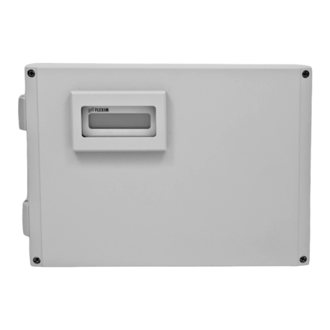
AFLOWT MT Pro M Series User manual

ELECTROMAGNETIC
FLOW METER
AFLOWT MF
Version “Pro-×××M×”
OPERATION MANUAL
ISO 9001:2015

2
* * *
Manufacturer quality management system is certified to
ISO 9001:2015
* * *
URL: http://www.aflowt.com

3
TABLE OF CONTENTS
INTRODUCTION.....................................................................................................4
DESIGN VERSIONS...............................................................................................5
1. DESCRIPTION....................................................................................................6
1.1. Application.............................................................................................6
1.2. Specifications ........................................................................................7
1.3. Metrological specifications.....................................................................8
1.4. Contents of the delivery package ..........................................................9
1.5. Design and operation...........................................................................10
1.5.1. Operating Principle and Arrangement of the Flowmeter ......................10
1.5.2. Operating modes.................................................................................11
1.5.3. Displaying results and external connections ........................................12
1.5.4. Logs ....................................................................................................18
1.5.5. Design.................................................................................................18
1.6. Marking and sealing.............................................................................19
2. OPERATION.....................................................................................................20
2.1. Operating restrictions...........................................................................20
2.2. Selecting standard size........................................................................21
2.3. Preparing for operation........................................................................23
2.4. Operation procedure............................................................................24
2.5. Troubleshooting...................................................................................26
3. MAINTENANCE................................................................................................27
4. PACKING, STORAGE AND TRANSPORTATION............................................28
APPENDIX A. View of components ......................................................................29
APPENDIX B. Schematics of input and outputs....................................................33
APPENDIX С. Configuring Pipeline Filling Settings ..............................................35

4
This document covers “AFLOWT MF” Electromagnetic Flowmeter
of “Pro-×××M×” model Pro-112MI, -122MI, -212MI, -222MI, -111MA,
-121MA, -211MA, -221MA, -112MC, -122MC, -212MC, -222MC herein-
after referred to as the flowmeter and contains information about its op-
eration and design.
Due to continuous improvement of the product policy actual flow-
meter’s specifications may differ from the data specified in this manual.
However, this will not affect its metrological characteristics and func-
tionality.
LIST OF ABBREVIATIONS
DN
MB
LCD
PC
EMF
MF
- Nominal Diameter
- Measuring Block
- Liquid Crystal Display
- Personal Computer
- Electromotive force
- Electromagnetic Flowmeter.
Certifying documents can be found online: www.awlowt.com

5
DESIGN VERSIONS
The design versions differ in form factor and functionality of the
measuring block, pipe connection type (design of the flow channel),
purpose with regard to medium (material of the electrodes and the liner
material of the inner surface of the pipe channel).
Product identification corresponding to the type of the measuring
block:
Pro - 1××M×
–
without the display module
Pro - 2××M×
–
with the display module
Product identification corresponding to the pipe connection type:
Pro - ×1×M×
–
connection type –"wafer" (available sizes: DN10-
DN150)
Pro - ×2×M×
–
connection type –flanged (available sizes: DN20-
DN300)
Product identification corresponding to the type of the flow channel
lining:
Pro - ××1M×
–
polyurethane lining of the flow channel
Pro - ××2M×
–
fluoroplastic lining of the flow channel
Product identification corresponding to the purpose with regard to
medium:
Pro - ×××МI
–
standard industry design (for non-aggressive liquids
without abrasive additives)
Pro - ×××МA
–
wear proof design (for abrasive liquids);
Pro - ×××МC
–
corrosion resistant design (for aggressive liquids)

6
1. DESCRIPTION
1.1. Application
1.1.1. "AFLOWT MF" electromagnetic flowmeter of “Pro-×××M×” model is de-
signed for measuring average volumetric flowrate and volume of vari-
ous electrically conductive liquids in a wide range of operating condi-
tions.
"AFLOWT MF" flowmeters can be used in a great variety of appli-
cations in power industry, oil, gas and mining industries, municipal en-
gineering as well as in iron and nonferrous, chemical, oil refining, cellu-
lose and paper, food and other industries. The flowmeters can be used
as a part of various integrated solutions, metering systems, automatic
process control systems etc.
The flowmeters can be installed in both metal, and plastic (metal-
plastic) pipes.
1.1.2. Depending on design type and firmware, "AFLOWT MF" flowmeters of
“Pro-×××М×” model perform the following functions:
- Measure average volumetric flow rate in either forward or reverse flow
directions
- Totalizing volume of forward and reverse flows independently or calcu-
lating their algebraic sum with regard to flow direction
- Batching of preset volume of liquid or in the start-stop mode, batching
and determining the amount of batched liquid, batching time and flow
rate
- Displaying measurement results and emergency conditions
- Outputting of measurement results to current, pulse or logical output
- Storing configuration settings in the Device’s non-volatile memory
- Automatic monitoring and displaying alarm conditions and faults
- Transferring measurement, diagnostic, configuration, log data etc. via
RS-485 serial interface
- Protecting configuration settings from unauthorized access.
The flowmeter is also capable of monitoring how the pipeline is
filled with liquid.

7
1.2. Specifications
1.2.1. The maximum Qmax, and the minimum Qmin flowrate values of meas-
ured average volumetric flowrates for various nominal diameters (DNs
of the flowmeter’s flow channel) are given in Table 1.
Table 1
Name of the
Parameter
Value
DN, mm
10
15
20
25
32
40
50
65
80
100
150
200
300
Qmax, m3/h
2.5
6.3
10.0
16.0
25.0
40.0
63.0
100
160
250
630
1000
2500
Qmin.110, m3/h
0.25
0.63
1.0
1.6
2.5
4.0
6.3
10.0
16.0
25.0
63.0
100
250
Qmin.180, m3/h
0.031
0.078
0.125
0.2
0.312
0.5
0.787
1.25
2.0
3.125
7.87
12.5
31.25
Qmin.1150, m3/h
0.016
0.042
0.066
0.106
0.166
0.266
0.42
0.666
1.066
1.666
4.2
6.66
16.66
- Qmin1/10, Qmin1/80, Qmin1/150 –minimal measured average volumetric flow
rate for the flowmeters with measuring range factor of 1:10, 1:80 and
1:150, respectively.
1.2.2. Flowmeter's sensitivity to flow velocity is 0.02 m/s.
1.2.3. Characteristics of the liquid-under-control:
- Specific conductivity –no less than 5·10-4S/m
- Flow velocity –up to 10 m/s
- Temperature –from −10 to 150°C with fluoroplastic lining, and from −10
to 70°C with polyurethane lining
- Pipeline pressure –up to 2.5 MPa.
1.2.4. Inputs and outputs of external communications:
- Universal outputs –2
- Control input –1
- Current output –1 (optional)
- RS-485 interface –1.
1.2.5. Storing of configuration settings:
- User log –up to 1000 records
- Configuration settings registry –up to 8000 records.
When powered off, the flowmeter stores configuration settings for
no less than 1 year.
1.2.6. Flowmeter Power Supply:
- Input voltage is a stabilized 22 …29 V DC voltages with pulse level of
no more than ±1.0%. The flowmeter can be powered from mains 220 V
50 Hz via optional secondary power source
- Power consumption is no more than 5.0 W.
1.2.7. Operational data:
- Mean time to failure –75 000 h

8
- mean life time is 12 years.
1.2.8. Environmental restrictions:
- Ambient temperature, from 5 to 50°C
- Relative humidity shall be no more than 80% at 35°C, without moisture
condensation
- Vibrational loads –within the range of 10-55 Hz, with displacement am-
plitude up to 0.35 mm
- Atmospheric pressure from 66.0 to 106.7 kPa.
Flowmeter protection level shall be IP65.
1.2.9. View, overall dimensions and weight are given in Appendix A.
1.3. Metrological specifications
1.3.1. Limits of permissible relative error for measurement, indication, logging,
storage and transferring the results of average volumetric flowrate and
volume measurement for various liquids and for any flow direction do
not exceed the following ranges:
± 0.5 % –for flowmeters with flowrate range from Qmax to 0.1Qmax
(Qmin.110)
± 1.0 % –for flowmeters with flowrate range from Qmax to
0.0125Qmax (Qmin.180)
±2.0% –for flowmeters with flowrate range from Qmax to
0.0067Qmax (Qmin.1150).
1.3.2. Limits of permissible relative error for recording time of totalizer opera-
tion are ±0.1 %.

9
1.4. Contents of the delivery package
Items of the delivery package are specified in Table 2.
Table 2
Name
Qty
Notes
Flowmeter
1
Notes 1
Secondary DC 24 V power source
1
Optional
Installation kit
1
Notes 2, 3
Passport
1
Operating documentation:
1
- Operation manual
- Installation manual
Notes
1. Flowmeter's nominal diameter and design type (see section
DESIGN VERSIONS) are specified in the purchase order.
2. Socket connectors for power and signal cables are included in the
standard supply.
3. Set of fittings can be provided for on-site installation at customer’s op-
tion either as specified in the purchase order.
Allowable pressure for the supplied set of fittings is 2.5 MPa.
Operating documentation for this product is available on:
www.aflowt.com.

10
1.5. Design and operation
1.5.1. Operating Principle and Arrangement of the Flowmeter
The flowmeter consists of the primary transducer (electromagnetic
flow sensor) and secondary converter which is a microprocessor-based
electronic measuring block (MB).
MF operation principle is based on measuring electromotive force
(EMF) induced in electrically conductive liquid when it flows in magnetic
field. The magnetic field is furnished in the flow sensor's inner channel
by a special electromagnetic system (see Fig.1)
FLOW TUBE MEASURING BLOCK
В
Е
Magnet winding
power supply
FLOW METER
Inductance
EMF
~ 220 V 50Hz
Switching
module
=24 V
Secondary
power source
Processing
module
Universal output N1
External button
Display
module
RS-485
Analog output
Universal output N2
Fig.1. Flowmeter's block diagram
The Electromagnetic Flow Sensor is designed as a hollow magne-
totransparent cylinder with solenoid coils located outside. The inside of
the cylinder is covered with an electrically insulating material. The in-
duced signal is picked up by two electrodes, which are in conductive
contact with the liquid under control.
Inductive electromotive force (EMF) Eis proportional to the mean
flow velocity v, distance between the electrodes d(which is equal to the
sensor's inner diameter), and magnetic field strength B:
E = k B d v,
where k is a linear factor.
Band dare constants for the flowmeter of a given standard size.
The value of electromotive force (EMF) is independent of liquid temper-
ature and viscosity, and also it is independent of conductivity provided
that the value of conductivity is no less than specified in the flowmeter's
specifications.
Considering the formula for inductive EMF, flow rate Qis calculated
as follows:
E
Bk4 d
v
4
d
Q2
.

11
Volume Vof the liquid passed through the flow sensor during the
time interval Тis calculated by the formula:
T
0dt)t(QV
.
The measuring block includes processing, communication and dis-
play (if applicable) modules.
The processing module:
- Provides power supply for solenoids
- Receives and processes the induced EMF signals, determines average
volumetric flow rate
- Totalizes volume and time of operation
- Performs equipment diagnostics
- Stores configuration settings and collected data.
The communication module:
- Generates the sequence of output pulses corresponding to measured
average volumetric flowrate (volume)
- Generates output current signal
- Generates flow direction signal, error signal in the form of logic signal
- Receives external control signal
- Provides data exchange with external devices via RS-485 serial inter-
face.
The display module (if present) provides displaying parameters on
the LCD display.
Flowmeter's functions depend on design type and are specified in
the purchase order.
1.5.2. Operating modes
1.5.2.1. The flowmeter operates in three modes:
- VERIFICATION –adjustment and calibration
- SERVICE –start-up procedures
- WORK –operation mode (user mode).
Flowmeter's operating modes are set by placing (removing) jump-
ers on J1 and J2 terminals, which are located on the board of the MB
processing module (see Fig.A.4) Combinations of jumpers with regard
to operating modes are specified in Table 3 ("+" means that the termi-
nal contacts are closed by a jumper, and "-" means that the terminal
contacts are opened).
Table 3
Name
of the mode
MB terminal pair
Mode description
J1
J2
VERIFICATION
–
+
Adjustment and calibration
SERVICE
+
–
Start-up procedures
WORK
–
–
Operation

12
1.5.2.2. The modes provide different options for modification of the device’s
configuration settings. The settings are reconfigured programmatically
via RS-485 interface.
In the WORK mode, only the settings which have no effect on the
flowmeter’s operation can be changed:
- Dose value set for the batching mode
- Serial interface properties
- Display settings.
In the SERVICE mode, in addition to the WORK mode options, the
operator can configure the following flowmeter’s operational settings:
- Flow cutoffs for measurement
- Settings for the general-purpose and current outputs and the control in-
put
- Settings for the flowrate signal filter and automatic flowrate setup mod-
ule. In the VERIFICATION mode, all configuration settings may be
changed. Device adjustment during manufacture and after-calibration
adjustment are made in this mode.
Configuring the settings in the SERVICE and WORK modes does
not affect flowmeter’s metrological characteristics and may be per-
formed on-site, if necessary. In the SERVICE and OPERATION modes,
adjustment and calibration settings are inaccessible.
All the modes provide options for viewing service and configuration
settings.
Flowmeter’s adjustment for measuring reverse flow is available at
customer’s option.
1.5.3. Displaying results and external connections
1.5.3.1. Displaying results
A two-line character LCD display of the flowmeter shows:
- When measuring (fig.2.a) –codes of ER situations and measurement
units (first line), measured parameters and measurement results (sec-
ond line)
- In the batching mode (fig.2.b) –batching settings and measurement
units (first and second lines).
c h l
Error message Dimension
Parameter name Current value
V + = 578423 Т =15:28 м:с !
Vm =1523.375 l
Dimension
Current value
Current value
Dimension
Parameter name
Parameter name
Error message
a) measurement mode b) batching mode
Fig.2. Flowmeter’s display view

13
Measurement units and number of displayed digits are given in Ta-
ble 4.
Table 4. Displaying measured parameters
Name
Description
Units
Number of digits (max)
Notes
integer part
fractional part
Q
Average volumetric flow rate
l/min
m3/h
Up to 10
Up to 3
Note 1
V
Total volumetotalized value
l, m3
Up to 9
Up to 3
Note 1
Note 2
V+
Forward flow volume
totalized value
l, m3
Up to 9
Up to 3
Note 2
V-
Reverse flow volume
totalized value
l, m3
Up to 9
Up to 3
Note 1
t
Time of totalizer operation
hours
Up to 10
-
Dose volume:
Note 3
Vs
- set value
l, m3
Up to 9
Up to 3
Vm
- measured value
l, m3
Up to 9
Up to 3
Notes
1. Reverse flow flowrate and volume, and negative values of total volume
are indicated by negative sign.
2. Totalized volume is the algebraic (considering the sign of the flow) sum
of flow volumes totalized for both forward (positive) and reverse (nega-
tive) flows. For unidirectional flowmeters, “Totalized volume” value
equals “Totalized volume of forward flow” value.
3. Dose volume set Vs and measured Vm values are displayed in the
batching mode only. One of the other parameters can be displayed
along with Vm value (see table 5).
Table 5. Displaying batching parameters
Line
number
Name of the
Parameter
Description
Measurement
units
1
Q
Average volumetric flow rate
l/min, m3/h
2
Vm
Dose volume, measured
l, m3
1
Vs
Dose volume, set
l, m3
2
Vm
Dose volume, measured
l, m3
1
T
Batching time
min, s
2
Vm
Dose volume, measured
l, m3
The set of displayed parameters, measurement units, display peri-
od and flow cutoff value may be set at the factory on customer request
or on site when putting the flowmeter into operation.
By default, the flowmeter is configured to display Vs / Vm parame-
ters during batching.
Indication Period (the time for one parameter to be displayed in
the automatic indication switching mode). This parameter is set pro-
grammatically from 1 to 100 s (5 s is a factory set value).

14
It is possible to switch indication by feeding the corresponding sig-
nal to the control input. To do this, select Menu navigation item for the
control input.
The first line of the display shows characters corresponding to
alarm or fault condition in the operation of the pipeline or to the failure
of the device (see fig.2a).
Character assignments are specified in section 2.5 of this manual.
1.5.3.2. Control input
Functions of the inputs are configurable:
- Start-Stop batching –to start and stop batching upon control signal
- Menu navigation –to switch over indication upon control signal.
Control input circuit diagrams and control signal characteristics are
given in Appendix B.
1.5.3.3. Universal outputs
The flowmeter has two galvanically isolated outputs N1 and N2.
These outputs are universal regarding both the operation modes (fre-
quency, pulse or logical) and function.
Operating mode, function and parameters of the outputs are con-
figured at the factory (if ordered) or on site (see table 6).
Circuit diagrams of output stages and description of their operation
modes are specified in Appendix B.
When working in the pulse and frequency modes, the outputs can
be used to output measurement results in the form of square pulse se-
quence with period-to-pulse duration ratio of 2 and standardized pulse
weight. The maximum pulse repetition rate is 500 Hz.
Output conversion constant Kp(pulse/l) that defines the pulse
weight may be set within the range from 0.0001 to 200 000 (minimal in-
crement of 0.0001). To determine Kphaving regard to the maximal flow
rate in the pipeline where the flowmeter is installed and frequency
characteristics of the input receiving the pulse signal, the following for-
mula may be used:
im
3
m
рQ101.8
QF3.6
p/lК
Qmax –maximum operational flowrate in the pipeline, m3/h
F –maximum flowmeter’s pulse repetition rate permissible for a re-
ceiving input, Hz
i=
2
Ti
–minimum flowmeter’s pulse duration permissible for a re-
ceiving input, ms
Ti–pulse repetition period on the flowmeter's output, ms.

15
Table 6. Functions of the universal outputs
Operating mode
of the output
Name on the PC’s display
Condition for the generating of the signal / changing state
on the output
Frequency
Modulo flow
Flowrate for any flow direction
Direct flow
Flowrate for direct (positive) flow direction
Reverse flow
Flowrate for reverse (negative) flow direction
Pulse
Modulo volume
Volume for any flow direction
Direct volume
Volume for direct flow
Reverse volume
Volume for reverse flow
Batching stop signal
Stop of the preset batch accumulation
Logic
Reverse flow
Flow direction is changed in the pipeline
Error Q>Qmax
Qmax value is exceeded
Any Error
Any error detected by the flowmeter
Batcher signal
Batching Start/ Stop
Reverse flow
(inertial)
Flow direction is changed in the pipeline during the
heat accounting
Power (“High” level)
Interruption of power supply
Empty pipe
Level of the probing signal applied to the electrodes
exceeds the preset threshold for the empty pipe
Error “Flow out of us-
er range”
Value of flowrate falls outside the specified range
Error Q>Qmax (user)
Current value of the flowrate exceeds the upper
limit of the preset operation range
Error Q<Qmin (user)
Current value of the flowrate is lower than the bot-
tom limit of the preset operation range
The default mode for N1 output is the frequency mode, and the de-
fault Kpvalues are specified in Table 7 which correspond to a frequen-
cy of 500 Hz at Qmax flowrate.
Table 7.
DN, mm
10
15
20
25
32
40
50
65
80
100
150
200
300
Kp, p/l
530
230
130
80
50
30
20
10
8
5
2
1
0.5
In the frequency mode, frequency is proportional to average volumetric
flowrate measured over previous 80 ms.
For the frequency mode, Kp, Maximal frequency and Error fre-
quency parameters are configured.
Maximum frequency is the frequency of the output signal corre-
sponding to the maximum flowrate in the pipeline. Exceeding Maxi-
mum frequency of the output signal is identified by the flowmeter as
an alarm condition, i.e. the value of Kpset for this output is incorrect.
Emergency frequency is the pulse repetition rate of a pulse se-
quence (no more than 700 Hz) generated on the output if the measured
flowrate exceeds Qmax for a given DN. The value set for Error frequen-
cy must be no less than the Maximum frequency value for the output.

16
Function of the output in the frequency mode is set by Modulo
flow, Direct flow and Reverse flow parameters.
Modulo flow –a pulse sequence with pulse repetition rate propor-
tional to the measured flowrate is generated on the output regardless of
flow direction. Direct flow –the pulse sequence is only generated for
forward flow. Reverse flow –the pulse sequence is only generated for
reverse flow.
In the pulse mode, a burst of pulses is generated on the output within a
second, in which the number of pulses (considering pulse weight) cor-
responds to the flow volume measured over the previous second.
In the pulse mode, Kpand Pulse period are set.
Pulse period –the pulse repetition period, may be set from 2 to
1000 ms (which corresponds to the frequencies from 500 to 1 Hz).
To set the function for the output in pulse mode, select Modulo
volume, Direct volume, Reverse volume or Batching stop signal.
Modulo volume –pulses the number of which is proportional to
the measured volume are generated on the output regardless of flow di-
rection. Direct volume –pulses are generated for direct flow only. Re-
verse volume –pulses are generated for reverse flow only.
Batching stop signal –one pulse is generated on the output when
batching stops.
In the logic mode, one signal level corresponds to “event”(or its state)
and the other level corresponds to “no event”(or another state).
For the logical mode, Activity level i.e. High or Low signal level is
set programmatically when the event is present. Electrical parameters
of the corresponding signal levels are specified in Appendix B.
To set the function for the logical output, the following options may
be selected:
- Reverse flow –signal level on the output is changed without lag when
the flow direction is changed
- Error Q> Qmax –Signal level on the output is changed if the actual
value of flowrate exceeds Qmax for a given DN
- Any Error –Signal level on the output is changed in case of any alarm
situation detected by the flowmeter.
- Batcher signal –Signal level on the output is changed at the start and
stop of batching
- Reverse flow (inertial) –signal level on the output is changed only if
period of changing flow direction exceeds the preset lag. T inertial flow
may be set from 2 to 60 min
- Power (“High” level) –High signal level is generated on the output if
power is applied to the Device, in case of power supply failure output
signal is absent

17
- Empty pipe –Signal level on the output is changed if the value of re-
sistance exceeds the threshold specified for the pipe filled with liquid
- Error “flow out of user range” –Signal level on the output is
changed, if the value of the flowrate falls outside the specified rate
- Error Q> Qmax (user) –Signal level on the output changes, if meas-
ured flowrate value exceeds the Qmax value
- Error Q> Qmax (user) –Signal level on the output changes, if meas-
ured flowrate value is lower than the Qmax value.
1.5.3.4. Current output
The current output of the flowmeter can operate in the range of 4-
20 mA. The current output is set by the optional.
Nominal static characteristic of the current output is calculated as
follows:
outmax
minout
ltutltvI-I I-I
)Q-(Q+Q=Q
,
where Qvis the measured flowrate, l/min;
Qlt –specified low setpoint for the current output corresponding
to Imin, l/min
Qut –specified high setpoint for the current output corresponding to
Imax, l/min
Iout –value of output current signal corresponding to the measured
flowrate, mA
Imax –maximum operating range for the current output (20), mA
Imax –minimum operating range for the current output (4), mA.
The current output is configured programmatically by setting the
operating range, setpoints and function. Modulo flow –current propor-
tional to the measured flowrate is generated on the output regardless of
flow direction. Direct flow –current is generated for direct flow. Re-
verse flow rate –current is generated for reverse flow only.
The following levels can also be generated on the current output:
- 3.2 mA –when flowmeter’s hardware fault takes place (e.g. deadlock),
or during flowmeter’s initialization when it is being connected to the ex-
ternal power source (after its successful startup, the output current is
set proportionally to the current flowrate)
- 24 mA –when measured flowrate Qmax is higher and Error current is
set. Parameters of the current output and circuit diagram are given in
Appendix B.
1.5.3.5. Serial interface
Serial interface RS-485 is used to transfer measurement and con-
figuration data and modify configuration parameters, if accessible.

18
RS-485 interface supports ModBus (RTU ModBus and ASCII
ModBus) protocol and provides cable communication between several
stations (one may be a PC) with maximum cable length up to 1200 m.
Data transfer rate (from 9600 to 115200 baud) as well as commu-
nication properties are set programmatically. By default, at the factory,
the transfer rate is set to 19200 bauds.
1.5.4. Logs User log and Configuration settings registry are provided in the
flowmeter for storing the configuration settings.
Parameters available for editing in the SERVICE mode are stored
in User log. This log can contain up to 1000 records. After log depth is
exhausted new records are written over the old ones starting from the
first (by the time of recording).
Configuration settings registry is used to store parameters available
for editing in the CALIBRATION mode. This log can contain up to 8000
records. After the log depth is exhausted it is impossible to add new
records. The lock is released by the manufacturer.
1.5.5. Design
The design of the flowmeter's flow pipe depending on the pipe
connection type may be as follows:
- Wafer connection type (DN10-DN150): flow pipe is fixed by studs be-
tween two flanges welded to the pipeline ends where the flowmeter is
cut in
- Flanged type (DN20-DN300): the flow pipe's flanges are bolted to the
mating flanges of the pipeline.
Depending on application, the inner surface of the flow pipe is lined
with fluoroplastic or polyurethane.
For the flowmeter's with fluoroplastic flow pipe, protection rings are
installed on the end faces of the flow pipe to protect fluoroplastic lining
from damages during mounting and operation. The protection rings en-
sure alignment of the inner channel of the flow pipe with the mating
flanges. Elements of the protection rings provide electrical contact of
the flowmeter with the fluid being measured during the installation in
plastic (metal-plastic) pipelines.
The measuring block (without the display) contains boards of the
processing and communication modules. Modules are placed within the
case of the MB and connected with each other through the connector.
MB with the display additionally contains in the cover of the front panel
the display module connected with the communication module via the
signal flexible flat cable. The MB is designed in a metal case. The cover
is connected with the case by the lower swivel hinge and fixed to it with
screws.
The flow pipe casing and hollow stand fixing the MB are made of
metal. It is possible to turn the MB about the stand axis by 90, 180or
270(factory-installed on customer's request).

19
The power supply cable and signal cables are entered into the
case via two cables through with M161.5 installation thread.
The screw on the MB foundation is used as the flowmeter’s
grounding terminal. The wires for connection with the pipeline mating
flanges are fastened to the screw.
1.6. Marking and sealing
1.6.1. The MB front panel bears (see fig.3):
- Name and identification
- Manufacturer's trademark
- Mark of conformity with EU Directives
- Design version
- MF standard size
- MF main specification.
Temperature class T 90
MAP 2.5MPa
Power supply 24VDC
MF Pro-212MI DN32 25m3/h/160
Device' s name Identification of the device
Flowmeter's
main
specification
Manufacturer's
trademark
Design version Flowmeter's size
Fig.3. Flowmeter’s marking
Serial number is indicated on the nameplate located on the MB
case. Power cable through on the MB case is marked as "=24VDC ".
1.6.2. After flowmeter calibration the MB’s terminal that allows modification of
calibration settings is sealed.
1.6.3. The MB’s terminal that allows modification of service settings can be
sealed after putting the flowmeter into operation.
Besides this, to protect the device from unauthorized access during
operation two fixing screws of the MB’s casing cover can be sealed.

20
2. OPERATION
2.1. Operating restrictions
2.1.1. Environmental restrictions are specified in section 1.2.8.
2.1.2. The flowmeter may be mounted into the pipeline installed horizontally,
vertically or obliquely. Special filters or dirt traps are not needed.
2.1.3. For precision and reliable operation, when choosing its mounting loca-
tion, the following conditions must be met:
- No air accumulation in the mounting location
- Liquid pressure in the pipeline must not be of values that may facilitate
gas release
- Straight pipe runs of appropriate length and DN equal to the flowmeter
DN must be provided at the floe channel’s input and output. The runs
must not include devices or components that may disturb flow structure
- When the flowmeter is operated, the inner volume of the flow channel
must be fully filled with liquid
- Intensity of external magnetic field (commercial frequency) should not
exceed 400 A/m.
CAUTION! DO NOT touch the electrodes inside the flow channel at
any time when working with the flowmeter.
Mounting considerations, mounting and dismounting instructions,
are given in “AFLOWT MF Electromagnetic Flowmeter of the Pro-
×××M×model. Installation Manual”.
CAUTION! If the flow channel is covered with fluoroplastic and the
protection rings are removed, DO NOT remove the tightening stud (bolt)
and clamping plates from the flow channel for more than 10 minutes.
2.1.4. Type and composition of medium (suspensions and their concentration,
impurity substances, etc.), operating mode and pipeline conditions must
not lead to sediments affecting performance and metrological charac-
teristics of the flowmeter.
To provide proper operation of the flowmeter in pipelines
equipped with carbon filters, it is necessary to keep the filters in
good condition.
2.1.5. The need for the protective grounding is determined on power supply
voltage and environment condition.
2.1.6. Lightning protection system for the site where the flowmeter is installed
protects it against failures caused by lightning strokes.
2.1.7. Mounting location and operating conditions requirements specified in
this operating documentation are based on the most typical factors af-
fecting Device's performance.
The external factors that cannot be foreseen, evaluated or tested
by the manufacturer during designing may exist or appear on site.
Table of contents
Other AFLOWT Measuring Instrument manuals
