Twilight TES-660 User manual

Dosímetro de Micro Ruido, I
ntrínsecamente Seguro, TES Clase 1
TE-660

Logging Personal
Noise Dosimeter
TES-660
INSTRUCTION MANUAL
TES ELECTRICAL ELECTRONIC CORP
.

CONTENTS
Title Page
1. GENERAL DESCRIPTION..............................................................................1
2. PRINCIPLE OF MEASURING ACCUMULATED NOISE EXPOSURE ..........1
3. INTRODUCTION TO THE DOSE METER......................................................1
4. SPECIFICATION .............................................................................................3
5. NOMENCLATURE AND FUNCTIONS............................................................6
5-1 The Display and keypad................................................................................6
5-2 The Windscreen and Microphone.................................................................7
5-3 The Mounting Clips .......................................................................................8
5-4 The Charger..................................................................................................9
6. CHARGING THE METER .............................................................................10
6-1 Charging......................................................................................................10
6-2 Linking Chargers Together.......................................................................... 11
6-3 Battery......................................................................................................... 11
7. GENERAL OPERATION...............................................................................12
7-1 Switching on the Meter................................................................................12
7-2 Calibrating the Meter...................................................................................14
7-3 Starting a Measurement Run ......................................................................16
7-4 Locking and Unlocking the Keys.................................................................16
7-5 Stopping a Measurement Run ....................................................................17
7-6 Pausing a Measurement Run .....................................................................17
7-7 Reviewing Measurement Run Data ............................................................18
7-8 Switching Off the Meter...............................................................................18
8. CONFIGURING THE METER .......................................................................18
8-1 LCD Contrast ..............................................................................................19
8-2 Date and Time.............................................................................................19
8-3 Display Timeout ( )............................................................................19
8-4 Selecting Dosimeter Setups........................................................................20
8-5 Pause Mode ().........................................................................................22
8-6 LED Alarms ( ) ....................................................................................22
8-7 Auto Lock ( )......................................................................................23
8-8 Autoscroll ( ).........................................................................................23
8-9 Timers ( )............................................................................................24
8-10 Data Memory Interval Time.......................................................................26
8-11 Language...................................................................................................27
8-12 Clear Memory............................................................................................27
9. RECALL THE MEMORIZED DATA ..............................................................28
10. SOFTWARE INSTALLATION AND OPERATION ........................................28
※Copyright © 2016 TES Electrical Electronic Corp. All rights reserved.

-1-
1. GENERAL DESCRIPTION
Thanks for you’re selecting Personal Noise Dose Meter. To ensure that you can get
the most from it we recommend that you read the manual carefully before use.
The personal noise dose meter is test equipment to evaluate the noise condition of
working environment by measuring the accumulated noise exposure. With this test
data, company can ensure the related noise regulation is followed or decide whether
or not to apply certain noise reduction action to avoid the acoustic trauma and
noise-induced hearing loss occurs to the working personnel.
Protected by: Taiwan: D174456
U.S.A.:
D768,514
China: ZL 2015 3 0269895.4
2. PRINCIPLE OF MEASURING ACCUMULATED NOISE EXPOSURE
DOSE is a parameter used to quantify noise exposure measured in a period, during
turns of % noise exposure relative to 90dBA for 8 hours.
i.e. 100% DOSE = 90dBA for 8 hours
This is known as the Criterion. Other criterion are available such as 100% DOSE =
85dBA for 8 hours to meet legislation in different countries.
If the person stayed in this environment for 4 hours, he would receive 50%DOSE.
Also if the noise level was say 93dBA, 3dB higher, a 100% DOSE would be
accumulated in only 4 hours, the above example is for a dose meter with 3dB
Exchange Rate, where a 3dB increase in sound level corresponds to a doubling
energy. A dose meter with 5dB Exchange Rate is also, available where the sound
must increase by 5dB to double the dose as required to meet noise legislation in
some countries.
3. INTRODUCTION TO THE DOSE METER
The Noise Dose Meter measure the frequency weighted noise exposures and peak
sound levels simultaneously.
The meter has the following features:
•Multiple simulated dosimeters (termed D1, D2 & D3)
•Simple operation, including direct read-out of results
•Ten built–in standard dose measurement setups:
OSHA-80, OSHA-90, MSHA-80, MSHA-90, DOD, ACGIH, ISO-85, ISO-90, NR-15
and NHO-01

-2-
•Pause function
•Nine user defined measurement setups
•30 dose (DATA) result stores
•Download of setups from PC to the meter
•Keypad lock protects meter against accidental operation
•Timers support pre–selection of measurement time and duration
•USB PC interface for the charging unit
The meter is ideal for quick on–site surveys and for monitoring personal noise
exposure in accordance with European ISO or USA OSHA, MSHA, DOD AND
ACGIH standards.
The meter is one measurement ranges: 70 – 140dB, A C & Z RMS weightings, A, C
& Z Peak weightings, Fast, Slow & Impulse time weightings, and energy exchange
rates (Q) of 3, 4, 5 & 6. In dose measurement mode, it display % dose, % dose
projected for an 8 hour period, peak level and measurement duration.
For countries that are subject to European Union regulations or the equivalent ISO
standards, the meter measure the daily sound exposure level (L
Aeq
,
8hr
, Pa
2
h
according to IEC 61252, which is identical with the L
EX,8h
required by ISO 1999),
while for USA OSHA/MSHA regulations they measure the Time Weighted Average
level (TWA).
When used as a sound level meter it display sound level, time-averaged (L
Aeq
) sound
level, peak and sound exposure level (SEL).

-3-
4. SPECIFICATION
Standard applied: IEC 61252: 2002, ANSI S1.25-1991 for dose meter and sound
exposure meters.
Microphone: 1/2-inch electret condenser microphone
Display: 128x64 graphic
Measurement Ranges:
Sound Level Range: 70 – 140dB (A, C)
90 – 140dB (
Z
)
Peak Ranges: 103 – 143dB Peak
Frequency Weightings: RMS Detector: A, C and Z
Peak Detector: A, C and Z
Frequency Range: 31.5Hz – 8kHz
Time Weightings: Fast, Slow and Impulse (RMS detector)
Exchange Rate: 3, 4, 5 or 6dB
Stabilization Time: 10 seconds from power on
Threshold and Criterion Levels:
From the setup, predefined in the built-
in setup according to applicable standards.
User–defined setups in the following ranges:
Threshold Level: 70 – 90dB in 1dB steps
Criterion Level: 70 – 90dB in 1dB steps
Overload Indications: At 0.1dB above the top of the selected measurement
range.
Under-Range Indications: At 1dB below the bottom of the selected measurement
range.
High Level Detector: 115dB ( )
Clock: Real-time clock with calendar.
Memory: Results from 30 measurements and 6101 data sets can be stored for
later viewing and download.
Measurement Control:
Measurement Duration: May be set 10 to 55 min in 5min steps or 1 to 24 Hrs in
1hr steps.
Timers: Up to 99 timers (automatic start and stop) can be set (maximum up to
one month ahead of measurement time).
Timer Controlled Started / Stop: Up to 16 timers can be set up from the PC
software or meter keypad
.

-4-
Setup: Ten built–in (predefined) default setups are included.
Nine additional user–defined setups can be stored.
Setup
OSHA
–80
OSHA
–90
MSHA
–80
MSHA
–90
DOD
ACGIH
ISO
–85
ISO
–90
NR
–15
NHO
-01
User1
–9
Measurement Range (dB)
70–140
70–140
70–140
70–140
70–140
70–140
70–140
70–140
70–140
70–140
70–140
Time Weighting
Slow
Slow
Slow
Slow
Slow
Slow
Fast
Fast
Slow
Slow
Fast
Frequency Weighting
A A A A A A A A A A A
Peak Frequency Weighting
ACZ
ACZ
ACZ
ACZ
ACZ
ACZ
ACZ
ACZ
ACZ
ACZ
ACZ
Exchange Rate
5 5 5 5 4 3 3 3 5 3 5
Threshold (dB)
80 90 80 90 80 80 70 70 80 80 80
Criterion Level (dB)
90 90 90 90 85 85 85 90 85 85 90
Allow User toChange Setup
No
No No No
No No No No No
No Yes
Exceedance Time LAS
>115dB
>115dB
>105dB
>105dB
>115dB
>115dB
>115dB
>115dB
>115dB
>115dB
>115dB
Measurement Parameters
For Dosimeter-1, Dosimeter-2 and Dosimeter-3:
DOSE (Dose), PDOSE (Pdos), TWA (Twa), PTWA (PTwa), LAVG (Lavg), LEPd
(Lepd), PLEPd (PLepd), Exceedance Time (Las>105 or Las >115), LEQ (Laeq,
Lceq or Lzeq), SEL (La
E
, L
CE
or L
ZE
), SEpa
2
h (Ea, Ec, Ez), PEAK (Pka, Pkc or Pkz),
LEX8H (Lex8h), PLEX8H (PLex8h), EXP
H
rs (Exph), EXPsec (Exps), NEN.
Only for Dosimeter-1:
Max/Min 18 parameters for A, C, Z and F, S, I weightings.
Statistical analysis 45 parameters L05, L10, L50, L90, L95 for A, C, Z and F, S, I
weightings for sampled at 20ms interval into 0.1dB wide classes.
Statistical analysis 5 parameters LAEQ05, LAEQ10, LAEQ50, LAEQ90, LAEQ95 for
LAEQ sampled at 1s intervals into 0.1dB wide classes.
Display parameters selecting by PC.
Output: USB interface from the charging unit (The charging unit must be power on).
Battery: 3.7V 470mAH Lithium Polymer (Flat cell).
Battery Life time: Typically > 15 hours at room temperature.
The meter will automatically stop the measurement and store the data before
the battery voltage gets too low.
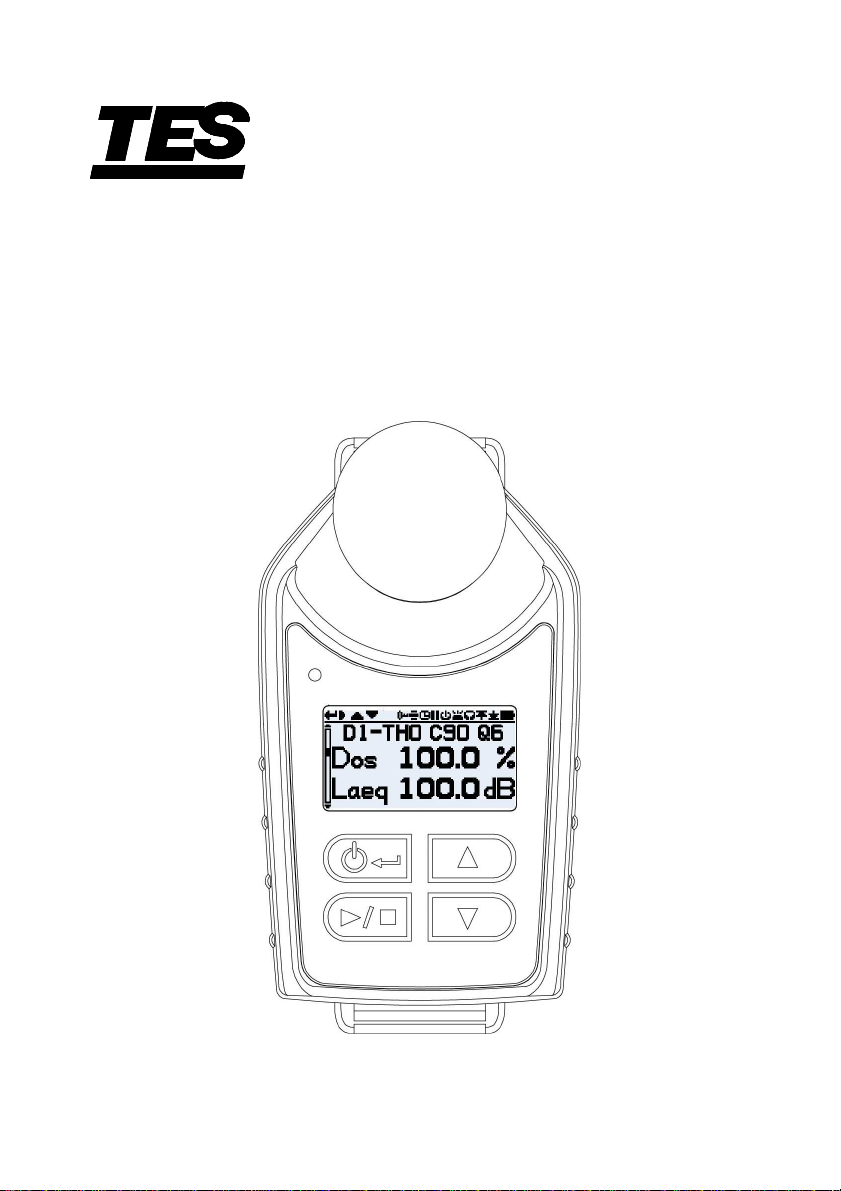
Battery Indicator: Symbol indication battery capacity.
“
” indicated flash when voltage is insufficient for operation.
Operating Temperature & Humidity: 0 – 50ºC (32 to 122ºF), 10 – 90%RH
Storage Temperature & Humidity: -10 – 60ºC (14 to 140ºF), 10 – 75%RH
Size: 84(L)×49(W)×55(H)mm / 3.3(L)×1.9(W)×2.2(H)inch (with windscreen)
Weight: Approx. 77g (2.7oz), less mounting device.
Accessories: Instruction manual, Charging unit, AC adaptor, Mounting clips,
Carrying case, Software CD, USB cable.

-5-
CE Certification:
CE-mark indicates compliance EMC Directive
EMC Emission
EN50081-1 (1992): Generic emission standard.
Part 1: Residential, commercial and light industry
EN50081-2 (1993): Generic emission standard.
Part 2: Industrial environment
CISPR22 (1993): Radio disturbance characteristics of
information technology equipment. Class B Limits
FCC Rules, Part 15: Complies with the Limits for a Class B
digital device
EMC Immunity
EN50082-1 (1992): Generic immunity standard.
Part 1: Residential, commercial and light industry
RF immuni
ty implies that sound level indications of 70dB or
greater will be affected by no more than ±1.5dB
EN 50082-2 (1995): Generic immunity standard.
Part 2: Industrial environment RF immunity implies that sound
level indications of 70dB or greater will be affected by no more
than ±1.5dB

-6-
5. NOMENCLATURE AND FUNCTIONS
5-1 The Display and keypad
1. Windscreen and microphone
2. LED indicator
Red: Charging indicator.
Blue: A flashing blue LED indicates the measured value has exceeded the alarm
setting value.
3. Display: View data and various indicators.
4.
key:
On/Off key: Press this key one time to turn on the meter.
Press and hold down this key, A “Power Off 3, 2, 1” countdown will
appear as the meter is powered off.
Enter key: Confirms action of other keys and settings.

-7-
5. ►/key:
►Run key: In STOP mode, Press and hold down this key, A “START 3, 2, 1”
countdown will appear as the meter is running.
Stop key: In Run mode, Press and hold down this key, A “STOP 3, 2, 1”
countdown will appear as the meter is stop, if the meter PAUSE mode
is setting to “OFF” otherwise A “PAUSE 3, 2, 1” countdown will appear
as the meter is pause.
6. Up key: Press this key to scroll through display views or setting up the parameters.
7.
Down key
: Press this key to scroll through display views orsetting down the
parameters.
5-2 The Windscreen and Microphone
During use, it is essential that the meter is fitted with the Windscreen. The
Windscreen protects the microphone from potential erroneous results due to air
movement passing over it but also helps to protect from dust ingress, moisture or
minor impact damage.
To calibrate the meter it is necessary to remove the Windscreen to expose the
microphone. To unscrew the Windscreen by turning the black ring (not the foam!)
in a anticlockwise direction.
It will not normally be necessary to remove the Microphone but to do so unscrew
anticlockwise direction. When refitting the Microphone, screw the Microphone on
clockwise until it fits tightly.
Following calibration refit the Windscreen, screw the Windscreen in a clockwise
and take care do not over tighten; finger tight is sufficient.
Windscreen
Microphone
(
Anticlockwise
)

-8-
5-3 The Mounting Clips
Upon delivery, the meter will be fitted with the Crocodile-style mounting clips on
flexible webbing to aid positioning as they can be fitted to virtually any clothing
type. The mounting clip is used for attaching the meter to clothing and should be
used where piercing the employees clothing is not desired.
The recommended location for mounting a personal noise exposure meter in a
position close to the ear (10 – 15 cm). The meter should therefore be mounted on
the apex of the shoulder to avoid reflections from the head which might otherwise
affect the measurements. Consult your local Legislation and Standards for more
information.
All mounting clips are attached the meter by two screws. By removing the screws
with the screwdriver the mounting clips can be changed.

-9-
Charger
Charger link plate
5-4 The Charger
The charger is a drop-in intelligent charger unit, required to download the meter
memory and/or to charger the meter internal Lithium Polymer battery. The charger
consists of the charger base, AC adaptor, link cable and the charger link plate.
Note that the meter should only be charged in non-hazardous areas in the
absence of any flammable atmospheres.
Link cable

-10-
6. CHARGING THE METER
6-1 Charging
The meter use internal Lithium polymer battery. Ensure the meter is fully charged
prior to use by placing in the charger. Note the meter will fit into charger unit
regardless of which mounting clips are attached.
Ensure the AC adapter is connected and the supply is switched on. The meter will
automatically switch on and display how much charge is within the meter. After
approximately 20 seconds the display will blank. Pressing either the , or
key will wake the display for a further 20 seconds to check progress. When the
meter is charging the red LED will on. The meter will display “FULL” once
charging is complete and the LED on the front of the meter will turn purple.
The LCD display
when the meter is on
and put on the
battery charger.
The LCD display
when the meter is
off and put on the
battery charger.

-11-
6-2 Linking Chargers Together
The charger can be linked to the another charger via the link cable and the
charger link plate. Up to 4 chargers can be linked.
6-3 Battery
The meter battery care best practices.
The meter incorporates a Lithium Polymer battery as a power source that with
proper care should give years of operational service. (Three years is typical)
Proper care includes these best practices.
● After use, it is best to charge the meter using the recommended charger prior
to storage for a prolonged period. A prolonged period is considered to be 2 or
more months. If the meter is to be stored for an even longer period, it is best
to take the meter out of storage and re-charge the meter every 2 – 3 months.
● Charge the meter in the recommended charger before attempting to turn it on
if the meter has not been used for a prolonged period or was stored in a low
battery condition.
● It is best not to store the meter for any period of time in low battery condition.
● If not using the meter it is best to keep the meter in a powered up the
recommended charger.

-12-
7. GENERAL OPERATION
7-1 Switching on the Meter
Once the meter is switched on by pressing the key, it will display a start-up
sequence, shown in as follows. This displays the meter firmware version (e.g. Rev
V1.0) and the current time and date, followed by the meter series number and the
“Custom Text” screen. The series number and text can be configured using the
CD software by PC.
(1sec)
(1sec)
If the Auto scroll mode has been disabled pressing the or key will scroll
through the available results from the last run depending upon how the meter was
configured.

-13-
(key)
(key)
(key)
(key)
(key)
(key)
(key)
(key)
(key)
(key)
(key)
(key)
(key)
(key)

-14-
7-1-1 Error Messages at Power Up
If there are any error messages they will appear after the start-up screens:
Battery < 1 Hr Memory
Warning messages appear when there is less than 1 hours charge or memory
full. Press any key to return to the default screen or alternatively these error
messages will time-out after 30 seconds. Please either re-charge, download
and /or erase data as required before continuing with a new measurement run.
7-2 Calibrating the Meter
It is best practice (and often mandatory) to field calibrate each meter both before
and after use. Which will also allow the target calibration level to be set as shown
on the calibrator’s own calibration certificate, nominally 94.0dB, 114.0dB or OFF
selecting by PC.
Note: The meter will not enter the calibration mode if a measurement run is taking
place. If a run is in progress, stop the run according to section 7-5.
The windscreen should be removed prior to calibration. Please refer to section 5-2.
Push the sound calibrator over the microphone as shown. The calibrator should be
pushed on without twisting until fully home and switched on.
SOUND-LEVEL
CALIBRATOR
114dB1KHz
OFF
94dB

-15-
The meter will automatically recognize a 1kHz calibration tone and enter the
calibration mode.
( key)
Press ↵
key to confirm you wish to calibrate,
or press
key to cancel the calibration. It will
take a few seconds to automatically calibrate
to 94.0dB or
114.0dB during which time a
progress bar is displayed as shown.
Once the meter has successfully calibrated
the “CAL OK” message will appear.
The meter is ready to take a measurement
once the calibrator has been removed and
the Windscreen re-fitted.
You may need to consult local regulations or
standards if the “before” and “after”
calibration values differ by more then
(typically) +/- 0.5dB e.g. section 12.2 of ISO
9612: 2009 suggest that measurement is
re-taken.

-16-
7-3 Starting a Measurement Run
Before starting a measurement run, ensure the Windscreen is re-fitted according
to section 5-2 and ensure there is sufficient battery life and memory by looking at
the default screen shown in section 7-1.
If necessary, charge the meter as described in section 6-1, if the memory is fully
either clear it as described in section 8-10 or download the data to PC.
Note: If the battery available is less than one hour or memory is fully, the run will
not start.
Timers are also available to automatically start and stop a measurement run or
halt a run after a fixed period. These options may be selected in the Configuration
menu, see section 8-9
To manually start a measurement run, press and hold down key which will
initiate a 3 second countdown as shown. The keys must remain depressed
during the countdown for the measurement run to begin; releasing during the
3-2-1 countdown will cease the operation.
Once the measurement has begun, the “
” mark is flashing displayed in the top
left of the screen. The display will cycle between the section 7-1 screens if the
Autoscroll mode has been selected in the configuration menu (see section 8-8) or
may be scrolled manually by pressing either the or key.
7-4 Locking and Unlocking the Keys
It is recommended that the meter is locked during a run to prevent the wearer
tampering and this can be down automatically upon the start of a run having first
selected “Auto Lock” in the configuration menu (see section 8-7) or manually as
follows.
Press key 3 times to enter the “Lock” mode, the “ ” mark is displayed.
To unlock the meter, press key 3 times, the “ ” mark is disappear.

-17-
7-5 Stopping a Measurement Run
If the meter is locked, unlock as described in section 7-4 above. To stop the
current measurement run, press and hold down the
key for the period of the 3
second countdown (releasing during the countdown will cease the operation).
The display will then show the data from the measurement run that had just been
completed. See section 7-1.
A new measurement run can be started immediately by following section 7-3.
7-6 Pausing a Measurement Run
Some measurement strategies may require a measurement run to be PAUSED
e.g. during a worker’s lunch break. To enable this function it must first be selected
in the configuration menu (see section 8-5).
When a measurement run is in progress, the action of pressing and hold down the
key for the period of the 3 second countdown to enter the pause mode
(releasing during the countdown will cease the operation).
Note: During PAUSED mode, all time history profile data is recorded and “paused
event” markers are saved into the data set. Cumulative values shown on
the display represent the measured data and excluded the time and noise
level during the paused intervals.
From the PAUSED screen:
– to continue the run, press the key as prompted by the “
” mark.
– to stop the run, press the key as prompted by the “
” mark and “STOP
Sure?” confirmation message will appear for 30 seconds then default back to
the PAUSE screen if no action is taken.
– To stop the run, press the key as prompted by the “
” mark.
– to return to the paused mode press the key.
Table of contents
Other Twilight Measuring Instrument manuals

Twilight
Twilight E2 Series User manual

Twilight
Twilight Palette Series User manual

Twilight
Twilight MP-2000 User manual

Twilight
Twilight ATAGO PAL-CLEANER User manual

Twilight
Twilight Tobias IQ150 User manual

Twilight
Twilight TENMARS TN-TM206 User manual

Twilight
Twilight LG-DM1306D User manual

Twilight
Twilight MC-SUP2000H User manual

Twilight
Twilight LT-DW6093 User manual

Twilight
Twilight FZ-MA100C User manual