2 IN/RandC/004-EN Rev. A | SM500F | Field mountable paperless recorder
3 Processor board replacement
1. Disconnect the recorder from the power supply.
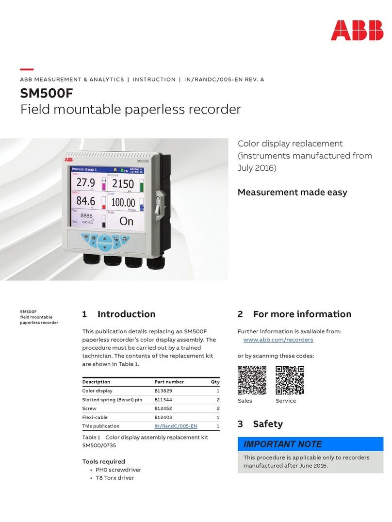
2. Referring to Fig. 3.1, unlock the door with the key A,
press release catch Band open the door.
3. Referring to Fig. 3.2, remove 6 Torx screws Csecuring
the door assembly rear cover and remove the rear cover.
Referring to Fig. 3.3:
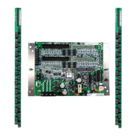
4. Disconnect processor board flexi-cable D, display
flexi-cable Eand keypad membrane cable Ffrom the
processor board and lift out and discard the processor
board.
5. Position the new processor board in the door housing and
reconnect keypad membrane cable F, display flexi-cable
Eand processor board flexi-cable D.
6. Referring to Fig. 3.2, refit the door assembly rear cover and
secure using 6 Torx screws C.
7. Close and lock the door.
8. Restore the recorder's power supply.
NOTICE – Property damage
The recorder is vulnerable to electrostatic damage.
Wear an anti-static strap or place the instrument on
an anti-static workbench.
Fig. 3.1 Opening the door
Fig. 3.2 Removing the rear cover
A
B
C
Fig. 3.3 Disconnecting the processor board
D
E
F
