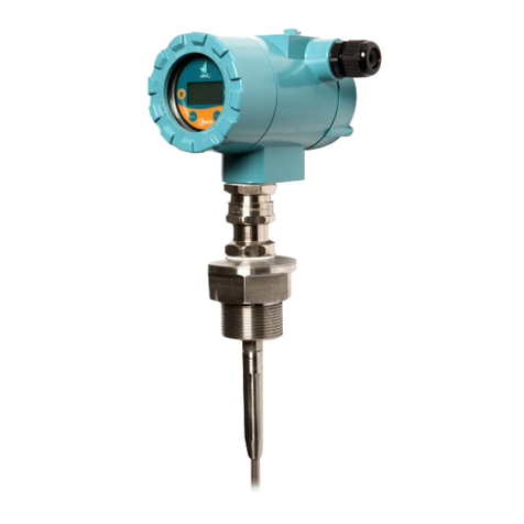
AFLOWT BUF User manual

BATTERY POWERED
ULTRASONIC FLOW METER
AFLOWT BUF
VERSION
BUF-311
OPERATION MANUAL
ISO 9001:2008

2
* * *
Manufacturer quality management system is certified to
ISO 9001:2008
* * *
URL: http://www.aflowt.com

3
TABLE OF CONTENTS Page
INTRODUCTION.....................................................................................................4
1. DESCRIPTION AND OPERATION.....................................................................5
1.1. Application.............................................................................................5
1.2 Specifications..........................................................................................6
1.3. Contents of the delivery package...........................................................7
1.4. Design and operation.............................................................................8
1.4.1. Operation principle .......................................................................8
1.4.2. Design ..........................................................................................9
1.4.3. Operating modes........................................................................10
1.4.4. Displaying measurement results.................................................11
1.4.5. External connections ..................................................................12
1.4.6. Logging.......................................................................................13
1.5. Design..................................................................................................14
1.6. Marking and sealing.............................................................................15
2. OPERATION.....................................................................................................16
2.1. Operating restrictions...........................................................................16
2.2. Safety instructions................................................................................16
2.3. Mounting the flow meter.......................................................................17
2.3.1. Mounting preparation..................................................................17
2.3.2. Mounting requirements...............................................................17
2.3.3. Length requirements for straight pipe runs.................................18
2.3.4. Mounting the flow meter flanged type on the pipeline.................18
2.3.5. Mounting the flowmeter with threaded coupling..........................19
2.3.6. Wiring the flow meter..................................................................19
2.3.7. Dismounting................................................................................20
2.4. Putting into operation...........................................................................20
3. MAINTENANCE................................................................................................21
4. CONTROLLING THE FLOW METER ...............................................................22
4.1. Configuring before work.......................................................................22
4.2. Troubleshooting...................................................................................26
5. PACKING, STORAGE AND TRANSPORTATION............................................27
APPENDIX A. General view .......................................................................28
APPENDIX B. Wiring diagrams ..................................................................31
APPENDIX C. Parameters to be set during on-site configuration...............33
APPENDIX D. Relative length of straight runs............................................36
APPENDIX E. Straightening vane design...................................................38

4
INTRODUCTION
This document covers battery powered ultrasonic flow meter
"AFLOWT BUF" of BUF-311 version (the flow meter below) and con-
tains the information about its operation and design.
Due to continuous improvement of product policy actual flow me-
ter’s specifications may differ from the data specified in this manual.
However, this will not affect the metrological characteristics and
functionality.
LIST OF ABBREVIATIONS
CP
CS
DN
ER
LCD
PC
PS
PEA
SPS
USS
- Primary converter
- Secondary measuring converter
- Nominal diameter
- Error
- Liquid crystal display
- Personal computer
- Pipeline section
- Electro-acoustic converter (transducer)
- Secondary power source
- Ultrasonic signal
NOTE. Words in the text marked in bold, for example, Low, corre-
spond to the items displayed on the flow meter's screen or PC display
when running "Viewer BUF-311" program.

5
1. DESCRIPTION AND OPERATION
1.1. Application
1.1.1. "AFLOWT BUF" battery powered ultrasonic flow meter of BUF-311 ver-
sion is designed to measure average volumetric flow rate and volume of
bidirectional flows of cold and hot water.
The flow meters may be used as part of metering systems and au-
tomatic process control systems in power industry and municipal engi-
neering applications.
1.1.2. "AFLOWT BUF" battery powered ultrasonic flow meter, BUF-311 ver-
sion, performs the following functions:
- Measuring average volumetric flow rate in either forward or reverse flow
directions
- Totalizing volume of forward and reverse flows independently or calcu-
lating their algebraic sum with regard to flow direction
- Determining the current value of flow velocity and flow direction
- Outputting measurement results to the frequency/pulse or logical output
- Logging of measurement data and configuration settings in the internal
nonvolatile memory
- Displaying measurement, configuration and history (logged) data on the
built-in indicator (LCD) and outputting the data to the external devices
via M-BUS interface or RS-485 interface
- Configuring the flow meter according to on-site and process require-
ments
- Monitoring and indicating alarm conditions (ER, error situations) and
faults; recording error and fault types and intervals into the correspond-
ing logs
- Protecting logged data and configuration settings from unauthorized ac-
cess.

6
1.2 Specifications
1.2.1. Specifications are listed in Table 1.
Table 1
Parameter
Value
1. Nominal diameter of the
pipeline, DN
32
40
50
65
80
100
125
150
200
250
300
2. Minimal measured average
volumetric flow rate Qmin, m3/h
0.11
0.18
0.28
0.48
0.73
1.13
1.77
2.50
4.53
7.10
10.15
3. Measured transient aver-
age volumetric flow rate Qtrans,
m3/h
0.55
0.9
1.40
2.40
3.60
5.70
8.80
12.7
22.6
35.4
50.9
4. Maximal measured average
volumetric flow rate Qmax, m3/h
14.5
22.6
35.4
59.8
90.6
141.5
221.1
318.4
566.0
885.0
1290
5. Sensitivity threshold, m3/h
0.022
0.036
0.06
0.10
0.15
0.24
0.35
0.54
0.96
1.50
2.16
6. Maximal pressure in the
pipeline, MPa
1.6 (2.5 –request)
7. Temperature of medium, °C
0-90 (130 –request)
8. Power supply voltage, V
3.6 from a lithium battery
9. Mean time to failure, h
75000
10. Mean life time, years
12
1.2.2. Under normal operating conditions*, the lithium battery keeps the flow
meter operational for at least 10 years without changing the battery.
*Normal operating conditions are as follows:
- Ambient temperature from +15 to +35 °C
- For frequency / pulse / logical outputs, maximal operating frequency of
no more than 8 Hz
- Logs are read (via interface) not more frequently than once a month
- LCD works no more than 3 min per day.
1.2.3. The flow meter measures average volumetric flow rate at flow velocity
ranging from 0.04 to 5.0 m/s. The relation between flow velocity v and
flow rate in the pipeline Q is determined by the following formula:
23- DN10×2.83 Q
=v
,
Where Q –average volumetric flow rate, m3/h;
v –flow velocity, m/s;
DN –nominal diameter of the pipeline, mm.
1.2.4. Limits of permissible relative error for measurement, indication, logging,
storage and transferring of average volumetric flow rate and volume
measurement results for any flow direction do not fall outside the follow-
ing ranges:
- From Qmin to Qtrans: no more than 4 %
- From Qtrans to Qmax: no more than 2%.
The real values of the errors no more (see fig.1):
- 1.0 % at v > 2.0 to 5.0 m/s
- 2.0 % at v > 0.10 to 2.0 m/s
- 4.0 % at v > 0.04 to 0.10 m/s.

7
+4%
+2%
-4%
-2% Qmin Qtrans Qmax
-1%
+1%
Fig.1. The figure is a real measurement error of the flow meter
1.2.5. The flow meter provides that the results of measurements can be out-
putted to:
- Universal output in the form of frequency, pulse or logical signal
- M-BUS interface
- RS-485 interface.
1.2.6. The flow meter provides storage of measurement results in the following
logs:
- Hourly log –120 records (hourly records)
- Daily log –45 records (daily records)
- Monthly log –48 records (monthly records)
- Opereting mode log –up to 100 records.
When powered off, the flow meter stores measurement results and
configuration settings for no less than 1 year.
1.2.7. The flow meter is powered from a built-in D-size lithium battery (3.6V
nominal voltage);
1.2.8. The flow meter complies with the following standards:
- Environmental resistance –ambient air temperature range is
+5...+65 °C; relative humidity is no more than 80 % at a temperature
≤35 °C, without moisture condensation
- Atmospheric pressure from 66.0 to 106.7 kPa.
Protection provided by the enclosure is IP65 (IP67 on request).
1.2.9. View, overall dimensions and weight are given in Appendix A.
1.3. Contents of the delivery package
1.3.1. Items of the delivery package are specified in Table 2.
Table 2
Item
Qty
Notes
1. Battery powered ultrasonic flow meter
1
Note
2. Installation kit
1
3. Operating documentation:
- Passport
1
- Operation manual and dedicated software
1
NOTE. The required items of the delivery package are specified in
the order sheet.
Operating documentation and order sheets for this product and
other products are available on www.aflowt.com.

8
1.4. Design and operation
1.4.1. Operation principle
1.4.1.1. The flow meter is designed on the base of a pulse-phase method of ul-
trasonic flow measurement. Its operation principle is based on
measuring the time difference between the time it takes for an
ultrasonic signal (USS) to travel through the liquid with the direction of
flow and against it.
Regarding the sounding principle, the flow meter utilizes the meth-
od of one-time simultaneous sounding. Flow meters of this type have
two simultaneously operating signal paths. Each signal path is formed
by a transmitting/receiving path of the flow meter consisting of electron-
ic circuitry [Secondary Converter (CS) and communications cables with
Electroacoustic Converters (PEAs)] and an acoustic path (PEA –fluid –
PEA).
1.4.1.2. PEAs are diametrically (see Fig.2) installed into the measuring section
(Pipeline Section, PS) making up together the Primary Converter (CP).
Fig.2. Diagram showing Pipeline Section (PS) with PEAs installed
1.4.1.3. The CS generates electric sounding pulses which simultaneously come
to PEA1 and PEA2.
USS generated by one PEA is projected through the liquid flowing
in the pipe and is received by the other PEA. Because of liquid flow, a
sound wave is shifted, which in turn leads to the difference in upstream
and downstream times of USS travel: it takes less time for an ultrasonic
signal to travel in the flow direction (from PEA1 to PEA2) than that in
the opposite direction (from PEA2 to PEA1). The difference in upstream
and downstream time of USS travel through an acoustic path dT is
proportional to flow velocity of fluid v and, correspondingly, to volumetric
flow rate Q.

9
1.4.1.4. The flow rate value is calculated only if the following condition is fulfilled:
Qmin Q,
Where Qmin –minimal value of the flow rate, m3/h;
Q –current value of the flow rate, m3/h.
The recommended value of low flow cutoff corresponds to the flow
meter's sensitivity threshold, m3/h.
If Q < Qmin, condition is fulfilled, the measured flow rate values are
displayed as zero, volume totalizing and pulse transmission to the
universal output are cancelled.
Under Q > Qmax condition (where Qmax corresponds to the flow
velocity value of 5 m/s), the metrological characteristics cannot be
ensured. The flow meter measures and displays flow rate values (de-
pending on temperature, liquid density etc.), however, volume totalizing
and logging, as well as pulse transmission to the Universal Output, are
cancelled.
1.4.2. Design The flow meter's block diagram is shown in Fig.3.
Fig.3. Flow meter's block diagram
BUF-311 flow meter includes the Primary Converter and Secondary
Measuring Converter.
The Primary Converter (CP) is a specially designed measuring pipe
section with one factory-supplied pair of PEAs installed on it.
Secondary Measuring Converter (CS) includes Measurement and
Calculation board, which is responsible for electroacoustic sounding
control, primary and secondary processing of measurement results as
well as for their storing in the memory.

10
To provide data exchange with external devices, Measurement and
Calculation board is equipped with Universal output, M-BUS output and
RS-485 output (optional).
The graphic Liquid Crystal Display (LCD) makes visible
measurement data. The LCD displays alpha-numeric data in two lines
(16 characters per line). Displayed data is updated with use of the
button located near the LCD on the front panel.
1.4.3. Operating modes
1.4.3.1. The flow meter operates in three modes:
- ADJUSTMENT –adjustment and calibration
- SERVICE –start-up procedures
- OPERATION –user mode.
The operating modes differ by level at which the user can access
certain data (transferred via RS-485 interface) and modify flow meter's
configuration settings.
Maximum rights are granted in ADJUSTMENT mode. The mode
allows the user to modify all of the configuration settings. Minimum
rights are given in OPERATION mode.
The set of displayed parameters is the same in all operating
modes.
Flow meter's work in different operating modes is controlled via RS-
485 interface.
1.4.3.2. Flow meter's operating modes are set by placing (removing) jumpers on
J1 and J2 terminals, which are located on the board of Secondary Cal-
culation module.
Combinations of jumpers with regard to operating modes are
specified in Table 3 ("+" means that the terminal contacts are closed by
a jumper, and "-" means that the terminal contacts are opened).
Table 3
Mode
Terminal
Mode description
J1
J2
OPERATION
-
-
Operation
SERVICE
-
+
Start-up procedures
ADJUSTMENT
+
-
Adjustment
1.4.3.3. OPERATION mode –flow meter's on-site operation.
In OPERATION mode, the user can view the following parameters:
1. On LCD: the current date and time, the values of the measured parame-
ters (volume flow, amounts accumulated in the forward and reverse di-
rection of flow, as well as their algebraic sum), the status of error situa-
tions (ER) and the version number of the software.
2. Via RS-485 or M-Bus:
a) Measurement values of: volumetric flow rate, flow volume totalized for
forward and reverse flow and their algebraic sum, velocity of liquid, cur-
rent value of USS velocity
b) Measurement data and "Mode" logs
c) Configuration settings: current date and time, specifications of output

11
d) Operation settings:
- Type of signal processing (median averaging, arithmetical averaging
etc)
- RS-485 settings
- Types of error situations.
1.4.3.4. SERVICE mode –start-up procedures.
In SERVICE mode, in addition to the above, available in OPERA-
TION mode, the operator can do the following (via RS-485 interface):
a) View:
- Configuration of measuring pipe section (device base, axis base, nomi-
nal diameter)
- Settings for ultrasonic signal detection.
b) Modify:
- Settings for flow meter's control via RS-485 interface (network address,
baud rate from 1200 to 4800 Baud)
- Settings for battery status monitoring
- Settings and operating modes for universal output
- Measurement units of volumetric flow rate (m3/h, l/min)
- Reading of built-in real time clock
- Automatic winter/summer time clock settings
c) Adjust LCD contrast and data update period
d) Initiate calculation of output scale factor or pulse weight for Universal
output
e) Clear logs.
1.4.3.5. ADJUSTMENT mode allows viewing and modifying all of the settings.
In ADJUSTMENT mode, in addition to the above, available in
OPERATION and SERVICE mode, the operator can do the following:
- Calibrate the flow meter
- Enter Device's serial number into the memory.
1.4.4. Displaying measurement results
1.4.4.1. List of displayed parameters is given in Table 4.
Table 4
Displayed
Parameter
Units
(format)
Number of displayed
symbols
Integer
part
Fract.
part
Time
Current date
XX.XX.XX
Data
Current date
XX:XX:XX
Q
Current value of volumetric flow
rate with regard to flow direction
(m3/h)
l/min
1-3
4
V+
Totalized volume of forward flow
m3; l
1-7
0-4
V-
Totalized volume of reverse flow
m3; l
1-7
0-4
ΣV
Total value of totalized volume
m3; l
1-7
0-4
Err
Status line
––––––
Ver
Number of software version
XX.XX.XX.XX

12
NOTES:
1. Flow rate and volume of reverse flow and negative values of total
volume are indicated by negative sign.
2. Totalized volume is the algebraic (considering the sign of the flow) sum
of flow volumes totalized for both forward (positive) and reverse
(negative) flows.
3. Counters are overflowed at V2109m3and restart from zero.
1.4.4.2. In SERVICE and ADJUSTMENT mode, the LCD is constantly on. In
OPERATION mode, measurement results listed in Table 4 cyclically
appear on the display on pressing the relevant button. With each
pressing of the button, the next parameter is indicated. When no button
is pressed during the period specified in the "Service" window of
Viewer BUF-311 program, the LCD goes off.
1.4.5. External connections
1.4.5.1. RS-485 interface
RS-485 serial interface is used to control the flow meter, read
measurement results, data logs, configuration settings, and diagnostic
data as well as to modify configuration settings. The RS-485 interface
supports ModBus (RTU ModBus and ASCII ModBus).
RS-485 interface supports cable communications among a group of
several end users, one of which can be a PC, at a distance of up to
1200 m.
The speed of communication via RS-485 and other communication
parameters are set from a PC.
1.4.5.2 M-Bus interface
Interface M-Bus interface complies with the standard EN 60870-5.
The interface allows reading of the measured and archived data.
Interface connections are made via two wires, the polarity is not
important. The rate of exchange via interface M-Bus is set from a PC.
1.4.5.3. Universal output
The flow meter is equipped with 1 galvanically connected output.
Universal output can operate in the frequency, pulse and logical
modes. Diagrams of output stages and description of their operation are
given in Fig.B.2, see Appendix B of the present manual.
Functions, working modes, specifications of output signals and
disconnection of the outputs are specified programmatically (see
section 4.1.3). Options available are specified in Table C.2, see
Appendix C of the present manual.
Operation modes of Universal output.
In the frequency mode, measurement results are outputted in the
form of square pulse sequence with period-to-pulse duration ratio of
2 and pulse repetition rate proportional to the current flowrate value.
The frequency output can be scaled by specifying the values for
"Maximum output frequency" and "Output conversion factor" pa-
rameters as well as for "Lower limit by flowrate" and "Up. limit by
flowrate" threshold flowrate values that correspond to zero and
maximum frequencies of the output signal. Maximum output fre-

13
quency value is 1000 Hz for ADJUSTMENT mode and 100 Hz for
OPERATION and SERVICE modes.
CAUTION! Please note that the higher the value of maximum
frequency, the faster the battery is discharged. The recommended
Fmax value is 8 Hz.
In the pulse mode, a burst of pulses is generated on the output
within a second, in which the number of pulses (considering Pulse
weight) corresponds to the flow volume measured over a previous
second. Maximum pulse repetition rate permissible in a burst (me-
ander-like, period-to-pulse duration ratio of 2) is 1000 Hz in AD-
JUSTMENT mode and 100 Hz in SERVICE mode.
CAUTION! Please note that increasing the number of pulses in a
burst results in a faster discharge of the battery. It is recommended to
set the value of pulse weight so that the number of pulses in a burst
does not exceed 8.
To provide correct work of Universal output, the parameters "Con-
version factor calculation" (pulses/m3) in the frequency mode and
“Pulse weight calcul.”(m3/pulse) in the pulse mode are calculated
automatically.
The conversion factor is calculated on the basis of user-specified
values set for the "Lower limit by flowrate" and "Upper limit by
flowrate" parameters and "Maximum output frequency" parameter.
The pulse weight is calculated from the values set for the "Up. limit by
flowrate" and "Pulse width" parameters. The pulse width can be set in
the range 1 to 500 ms.
In the logic mode, one signal level corresponds to “event” (or its
state) and the other level corresponds to “no event” (or another
state).
Programmatically this means: "Active level", i.e. "Low" or "High"
signal level is set when the event is present. Electrical parameters of
corresponding signal levels are specified in Appendix B.
The flow meter is delivered preset so that the universal output is
disabled.
1.4.6. Logging
1.4.6.1. Measurement results are recorded into the flow meter's internal logs:
hourly, daily and monthly logs. Logs are accessed via RS-485 and M-
Bus interfaces.
Hourly, daily, and monthly logs are arranged as circular buffers and
have the same structure.
Log capacity:
- Hourly log –120 records (hourly records)
- Daily log –45 records (daily records)
- Monthly log –48 records (monthly records).
Format of one record is as follows:
- V+ –total volume for direct flow over logging interval, m3(l)
- V- –total volume for reverse flow over logging interval, m3(l)
- Errors –code of error situation

14
- Time of errors –duration of error situation
- Operating time –time of totalizer operation.
1.4.6.2. Modifications made on the operation mode are logged in the Operation
mode log with a capacity of 100 records.
Mode log format is as follows:
- Order number of the record
- Name of the active operation mode
- Date and time of activation.
1.5. Design
1.5.1. The Measuring pipe section (PS) with the Secondary converter (CS) in-
stalled on it are delivered as an assembly unit.
The design of the flowmeter's depends on the pipe connection type
and may be as follows:
- Flanged type (DN32-DN300): PCF flanges are bolted to the mating
pipeline flanges (see Fig.A.1 Appendix A);
- Threaded coupling connection type only DN32, DN40 and DN50 (see
Fig.A.2).
1.5.2. Electro-acoustic converters
1.5.2.1. PEAs alternately operate in two modes: transmitter mode, in which the
electrical pulse signal coming from the CS is transduced into ultrasonic
waves, and receiver mode, in which ultrasonic waves in liquid are
transduced into the corresponding electrical signal.
1.5.2.2. The flow meter works with built-in PEAs.
The built-in PEAs come in cylindrical case with the transmitting
plane in the form of a disk in the flat end. The built-in PEAs are
mounted onto the Measuring pipe section so that the transmitting
(radiating) plane contacts the medium. Pipeline-PEA contact surface is
sealed.
The PEAs and CS are connected by twisted pair cables.
1.5.3. The CS is directly installed on the measuring PS and includes
Measurement and Calculation board. The board is placed in the trans-
parent cover of the case (on the front panel, see Fig.A.3). The cables
connections with the PEA and the interface cable are entered into the
case through cable glands of SKINTOP type.

15
1.6. Marking and sealing
1.6.1. The marking on the front panel of the CS contains:
- Flow meter's name and designation
- Nominal diameter
- Pulse weight on the universal output
- Maximal pressure
- Case protection
- Minimal, nominal and maximal measured average volumetric flow rate
- Production year
1.6.2. The cap covering J1 terminal, used to enable modification of calibration
settings, is sealed after performing calibration (see Fig.A.2, Appendix
A).
1.6.3. J2 terminal used to enable modification of flow meter's operation set-
tings is sealed on completing start-up procedures and putting the De-
vice into operation.
1.6.4. To protect the device from unauthorized access during transportation,
seals may be hung through the lugs located on the front and rear
panels.

16
2. OPERATION
2.1. Operating restrictions
2.1.1. Environmental restrictions with regard to the factors affecting the
performance and characteristics of the controlled medium shall comply
with the requirements specified in the operating documentation.
2.1.2. For precision and reliable operation, when choosing CP mounting
location, the following conditions must be met:
- Liquid pressure in the pipeline and pipeline's operational characteristics
must not be of values that may facilitate gas release and/or gas (air)
collection
- When the flow meter is operated, the PS should be fully filled with liquid.
2.1.3. Type and composition of medium (suspensions and their concentration,
impurity substances, etc.), operating mode and pipeline conditions must
not lead to corrosion and/or sediments affecting the performance and
metrological characteristics of the flow meter.
2.1.4. Lightning protection system for the site where the flow meter is located
protects the device against failures caused by lightning strokes.
2.1.5. Mounting location and operating conditions requirements specified in
this operating documentation are based on the most typical factors af-
fecting flow meter performance.
The external factors that cannot be foreseen, evaluated or tested
by the manufacturer during designing may exist or appear on site.
In this case, it is necessary to eliminate these factors or place the
flow meter in other location.
2.2. Safety instructions
2.2.1. The flow meter should only be used by the technical staff familiar with all
operating documentation for the product.
2.2.2. When working with the flow meter, the dangerous factors are as follows:
- Pipeline pressure
- Liquid temperature
- Other site-specific factors.
2.2.3. On detecting external defects on the device or damages to mains
cabling, you must remove power from the device and contact the
authorized technician for the information about the device's operability.
2.2.4. In the course of mounting, start-up or repair works you must not:
- Make connections to the flow meter, switch over modes and replace
electronic components, if the flow meter is powered up
- Remove the flow meter's components from the pipeline until pressure in
the pipeline section worked on is fully released
- Use defective electronic devices and electric tools or use them without
proper grounding (neutral earthing).

17
2.3. Mounting the flow meter
2.3.1. Mounting preparation
2.3.1.1. When mounting the flow meter on site, a free pipeline section should be
provided.
2.3.1.2. The flow meter should be transported packed in the manufacturer’s box.
After the flow meter has been moved to the mounting location from
a cold environment into a warm one (with ambient temperature above
zero), it shall be left to stand in the manufacturer’s box for at least 3
hours to make sure that no condensation remains inside.
When unpacking the flow meter, check that the delivery package
contains all items specified in the Equipment Certificate.
2.3.2. Mounting requirements
2.3.2.1. The requirements for on-site mounting of the flow meter are specified in
section 2.1.2.
The CP can be mounted into the pipeline horizontally, vertically, or
obliquely (Fig.4). The CP should not be placed at the upper point of the
pipeline. The recommended location (if applicable) is at the lower or
uprising pipeline section.
Fig.4. Recommended locations of the CP
NOTE. In case of impossibility of installation of a flow meter in rec-
ommended places device installation in the top point of the pipeline is
allowed. Installation of the air valve in the point which is above is thus
necessary is more true points of flowing part of a flow meter, for exam-
ple in pipeline expansion.
ATTENTION! It is necessary to watch serviceability of the air
valve. Correct work of a flow meter is possible only in the absence
of air in the channel.
2.3.2.2. The difference in the internal diameters of the pipeline and measuring
Pipe Section (PS) of the CP at link up points should not exceed
0.05 ·DN.
2.3.2.3. When mounting the CP on the pipeline, it should be placed so that the
PEA longitudinal axis (the axis that runs through the PEA pair along the
pipeline axis) would make an angle with the vertical of = 45-90
(Fig.5).

18
Fig.5. Recommended locations of PEA pair
2.3.3. Length requirements for straight pipe runs
2.3.3.1. For proper operation of the flow meter, before the first and the last PEA
with respect to the flow direction, there should be straight pipe runs of
corresponding length with the DN equal to the DN of the CP. Table D.1
given in Appendix D shows minimum values of relative length of
pipeline straight runs that should be used for typical installations.
The length of the straight pipe run L (mm) is calculated as follows:
DNN=L ×
,
where N is the relative length defined in the number of DNs and specified
in Table D.1;
DN –CP nominal diameter, mm.
CAUTION! While measuring the reverse flow, all the PEAs are in
upstream position, and the length of the straight pipe runs shall be
defined in view of this condition.
2.3.3.2. Any diaphragm or venturi type structure, as well as any valve, refer to
the type of hydraulic resistance specified in Appendix D as “control
valve”.
2.3.3.3. In case of mounting the straightening vane into the pipeline before the
measuring Pipe Section (Appendix E), reduction of straight pipe run
length is possible at the inlet of the CP up to two times. In this case, the
required length of the straight pipe run is defined on the base of site
survey, and the individual measurement technique shall be designed for
this structure.
2.3.4. Mounting the flow meter flanged type on the pipeline
2.3.4.1. Before working on the pipeline at the CP mounting location, fix the pipe
sections that may tip out of their axes after cutting the pipeline.
CAUTION! Before mounting the flow meter, it is necessary to
cut off liquid flow in the pipeline section where the flow meter will
be installed, make sure that pressure is released and drain the liq-
uid.
2.3.4.2. Cut a pipe run of the required length at the selected liquid-free pipeline
section. Join the flow meter's flanges with the companion flanges pro-
vided in the delivery package and bolt them together. Make several tack
welds between the cut ends of the pipeline and companion flanges.
Then, remove the flow meter and finally weld the flanges to the pipeline.

19
Alignment of the whole unit and flatness/parallel alignment of the flang-
es for the CP to be mounted between them must be provided.
2.3.4.3. Mount the flow meter on the pipeline provided that the arrow on the CP
points to the flow direction. Put rubberized asbestos fabric gaskets
between the mating flanges and bolt the flanges.
CAUTION! IT IS STRICTLY FORBIDDEN to throw the flow meter
and hit it while mounting. This can cause damage to the PEAs installed
on it. DO NOT take the flow meter by the CS case or PEA connection
cables. It is STRICTLY FORBIDDEN to dismantle PEA from assembly
branch pipes. During welding, PROVIDE the CS cable and PEA cables
with adequate protection from sparks. The welding temperature at the
PEA section SHALL BE lower than 100 C.
2.3.5. Mounting the flowmeter with threaded coupling
2.3.5.1. Select the flowmeter’s pipeline mounting location observing the rules
specified in section 2.3.2.
2.3.5.2. Unscrew grooved nuts and dismount nipple joints which are the parts of
flowmeter.
2.3.5.3. Make sure that the simulator is installed into the assembly-welded struc-
ture instead of flowmeter, this is necessary to provide alignment be-
tween two welded units and to avoid damages to the flowmeter during
welding the structure to the pipeline.
Weld conical nozzles to the pipeline butt-to-butt in the same way as
to weld the adaptor pipes for the wafer type flowmeters, so that the
nozzle axis is perpendicular to the grooved nut plane. Welding works
shall be conducted in accordance with the requirements given in section
2.3.4.
CAUTION! When replacing the simulator by the flowmeter after
welding, it is recommended to use a compensator to ensure that the
threaded couplings are moved apart by the distance of no less than
10 mm. The compensator may be as follows:
- KRK manufactured by JSC "ArmaTreid"
- ARN/HYDRA by Danfoss
- Compensators from "WILLBRANDT" (authorized distributor is
"KREOLAIN" company), or similar.
The compensator shall be mounted into the pipeline following the
instructions outlined in the corresponding operational (maintenance)
documentation.
2.3.5.4. Replace the simulator with the flowmeter. The whole structure is as-
sembled by firm tightening of grooved nuts. When assembling the struc-
ture, it is required to install gaskets made of edible material and sup-
plied with the flowmeter, between the nozzles and grooved nuts.
2.3.6. Wiring the flow meter
2.3.6.1. The flow meter’s power cable and CS-external devices connection ca-
bles (if applicable) are laid in accordance with the flow meter’s operat-
ing conditions.
2.3.6.2. Communications and network cables are fixed on the wall wherever
possible. The network cable is laid separately at a distance of 30 cm as

20
a minimum from other cables. To avoid mechanical damages, it is
recommended to place all cables in metal tubes or sleeves.
With presence of high-level electromagnetic interference (for
instance, from a thyristor controller) IT IS FORBIDDEN to lay the cables
without putting them into properly grounded (neutrally earthed) metal
tubes or sleeves.
2.3.6.3. It is recommended not to coil the excessive cables.
2.3.6.4. Prior to connection, cut insulation from cable ends. The cables are di-
rected via cable-through holes and attached to the connectors accord-
ing to the Wiring diagram given in Fig.B.1, see Appendix B. Refer to
Fig.A.2 of Appendix A for orientation of the connectors on the Meas-
urement and Calculation Board.
2.3.7. Dismounting
To dismount the flow meter, do the following:
- Cut off liquid flow in the relevant pipeline section, ensure there is no
pressure in the pipeline and drain the liquid
- Disconnect a lithium battery
- Disconnect cables leading to the CS
- Dismount the flow meter.
When the device is dispatched for calibration or repair, the PS and
emitting surfaces of built-in PEAs should be cleaned off sediments,
residue, scale, etc.
2.4. Putting into operation
2.4.1. Start-up works shall be performed by the manufacturer or by an entity
certified for performing works of this type.
2.4.2. The pipeline is filled with liquid to be controlled. Connects a lithium bat-
tery and the flow meter is connected to a PC, and configured according
to the instructions listed in section 4.1 of the present manual.
2.4.3. At first power-up or after a long break in operation, the flow meter be-
comes operational after all hydraulic processes in the pipeline related to
flow adjustment (draining, flow cut off, etc.) are fully completed.
2.4.4. When putting the flow meter into operation check the following:
- The flow meter and related equipment are connected in accordance
with the selected wiring diagram
- Output operates in the preset modes.
After putting the flow meter into operation, two fixing screws ac-
cessed from the CS front panel side can be sealed to protect the
equipment from unauthorized access.
This manual suits for next models
1
Table of contents
Other AFLOWT Measuring Instrument manuals


