AFP Imaging IMAGE-VET 70 ACP Manual

Visionary Imaging
Installation, Operation
&
Service Manual
Veterinary Diagnostic X-ray Unit
With Anatomical Timer Control
AFP Imaging Corporation
250 Clearbrook Road
Elmsford, NY 10523
©AFP Imaging Corp., 2007 P/N 897-000022


1
IMPORTANT!
BEFORE INSTALLATION
These instructions describe the installation, operation and maintenance procedures for the
Image-Vet 70ACP veterinary X-ray system. One purpose of this manual is to provide the user with
instructions that will permit the equipment to run safely and efficiently. The Image-Vet 70ACP must
be used according to the procedures in the manual and never for purposes other than the ones
for which it has been designed. Please read the operation instructions, Section A of this manual
in its entirety before attempting to take any radiographs of a patient. The Image-Vet 70ACP is
intended solely for veterinary applications and for use by a qualified and licensed veterinarian or
technician. These instructions apply to all the versions of the Image-Vet 70ACP X-ray equipment
as well as various accessories that may be provided. For this reason, the description of some
parts may not correspond or be applicable to your equipment.
The manufacturer or its representative shall provide authorized service to meet the stated
performance standard information as required for the timer or tubehead.
No part of this manual may be reproduced, stored in a retrieval system or transmitted in any form
or by any means, I.E. electronic, mechanical, photocopying, translation, or otherwise, without the
prior written permission of AFP Imaging Corp., © AFP Imaging Corporation, 2007.
All information, specifications and illustrations contained herein are subject to change.
AFP Imaging Corp. has a company policy of continual development. Therefore, it reserves the
right to make changes without prior notice.
AFP’s limited warranty obligations apply to, but are not limited by the following conditions:
1) Damage incurred due to improper wiring or connections are excluded.
2) The installation must be carried out by authorized personnel.
3) The installation must be completed in accordance with the diagrams supplied by
the manufacturer.
4) An independent earth ground wire is required for electrical safety with main power input
wiring.
Important: An electrical source must be provided with + or - 3%
regulation which includes a fuse or circuit breaker rated for 120/220 VAC,
15 Amps.

2
ABOUT THIS PRODUCT...
Performance
The Image-Vet 70ACP X-ray system is designed for use in veterinary dental
radiography. It is an AC type X-ray system that houses both the high voltage
transformer and tube insert in a compact tubehead assembly. This assembly is
supported by a spring loaded articulating arm that is balanced to provide smooth
movement and positioning of the tubehead in a variety of positions.
The positioning arm is atttached to a pivoting extension arm that, in turn, is
attached to a wall mounted plate. A remote exposure control providing voltage
to the tubehead is wall mounted and provides for precisely timed exposures.
The system provides for X-ray exposures on a variety of media from film to
CCD or CMOS digital sensors to PSP (Photo Stimulated Phosphor) plates.
The system is designed and manufactured to perform in accordance
with the manufacturer's certification, which is based upon FDA
regulations for X-ray sources and International IEC standards.
Performance qualification criteria is available from the manufacturer.
This device is for veterinary use only and is not certified for human application.
Disposal
The Image-Vet 70ACP Intraoral X-ray System, (except for the
tubehead), may be disposed of by any means appropriate for the
discard of electro-mechanical devices.
The Image-Vet 70ACP X-ray tubehead contains mineral oil, which is classified as a special
by-product. Therefore, when the tubehead is to be taken out of service, it should be sent
back to the manufacturer or given to a firm authorized to dispose of the mineral oil.
3
REVISION RECORD
Title: Image-Vet 70ACP Installation, Operation & Service Manual
Document Number: 897-000022
Revision Effective Date Description
01 August, 2004 Initial Release
02 November, 2004 Full Revision
03 May, 2007 Partial Revision
INSPECTION RECORD
Inspection Effective Date Description/Notes
01
02
03
04
05

4
SECTION A: OPERATORS MANUAL
Image-Vet 70ACP
TABLE OF CONTENTS:
A1. WARNINGS 5 - 6
A1.1. Ambient conditions 7
A1.2. Purpose of the equipment 7
A1.3. Improper use 7
A1.4. Protection against radiation 7
A1.5. Compliance with current standards and regulations 8
A2. DESCRIPTION OF THE Image-Vet 70ACP 9 - 10
X-RAY EQUIPMENT
A2.1. Nameplates 11
A3. USE OFTHE Image-Vet 70ACP 12
A3.1. Patient’s position 12
A3.2. Positioning the X-ray tubehead 12
A3.2.1. Bisector technique 12
A3.2.2. Interproximal radiographs 12
A3.3. Turning on the X-Mind control 13
A3.3.1. Display status 13
A3.4. Factory settings 13
14
A3.5. Setting the exposure time 15
A3.5.1. Exposure time chart 16
A4. DEVELOPING THE FILM 18
A5. CLEANING AND DISINFECTION 19
A5.1. Cleaning and disinfection instructions 19
A6. MAINTENANCE 20
A6.1. Periodic maintenance 20
A6.2. Malfunction and error messages 20 - 21
A7. SPECIFICATIONS 22 - 23
A8. FUSES 23
B1. - 6. SECTION B: INSTALLATION MANUAL 25 - 50

5
�
C US
12
A1. Warning Symbols & Labelling
Pay careful attention to the symbols contained herein and on
the equipment.
Certain instructions are preceded by Warning! with a triangle at
the side. Whenever this symbol appears, carefully read the
relevant paragraph before performing any operations. See symbol #2
Definitions of symbols used:
1) Degree of protection when coming directly or
indirectly into contact with live electrical parts.
(Class I, Type B)
2) CAUTION! Consult the technical documentation
provided.
3) Earth ground connection
4) Alternating current
5) On
6) Off
7) Source of radiation
8) Radiation exposure control
9) Ionizing radiation warning
10) Equipment which conforms with the EEC Directive
93/42 standards
11) I.M.Q. kite mark
12) CSA Mark

6
Before leaving the operatory, turn the main switch to the “Off” position.
The equipment is not liquid-proof. Do not immerse components.
The equipment is not suitable for use in the presence of flammable anaesthetic gas based on
oxygen and nitrous oxide.
WARNING!
If electrical equipment which does not comform with local codes for shield-
ing and isolation and/or FCC Part 15 of the FCC rules for class A computing
devices is used in operatories and/or nearby, interferences and/or distur-
bances may arise thus causing the X-ray equipment to malfunction.
In this case, DISCONNECT the X-ray equipment before using any other instrument or device.
The limited warranty will be voided if the following precautions are not taken:
· Assembly, servicing and modifications to the equipment should only be carried out by AFP Corp.
authorized technicians.
· Observe the conditions specified in the limited warranty certificate itself.
· The electrical supply wiring in the room where the equipment is installed must conform with the
National Electrical Council (NEC) specifications or other local electrical codes ( i.e. the regulations
concerning the electrical wiring to be used in operatories).
· The room where the X-ray equipment is installed must conform with the regulations, concerning
protection against radiation, in force in the locality where the equipment is used.
Assembly, repairs, modifications, adjustments and any other operations which involve gaining ac-
cess to the inside of the equipment must only be carried out by AFP Corp. authorized technicians
or representatives.

7
A1.1. Ambient conditions
The place where the equipment is to be installed should satisfy the following conditions:
a) Temperature between 50° and 105° F (10° and 40° C)
b) Relative humidity from 30 to 75%
c) Atmospheric pressure from 700 to 1060 hPa.
A1.2. Purpose of the equipment
The Image-Vet 70ACP veterinary dental X-ray system is designed for radiographic diagnosis
in the field of veterinary dentistry. Operation of this equipment must be under the direction or
supervision of a licensed veterinarian.
WARNING!
The Image-Vet 70ACP X-ray tubehead contains mineral oil, which is
classified as a special by-product. Therefore, when the tubehead is to be
taken out of service it should be sent back to the manufacturer or given to
a firm authorized to dispose of the mineral oil.
A1.3. Improper use
The Manufacturer declines all responsibilities if:
Installation, adjustment, repairs and modifications are carried out by persons who have not been
authorized by AFP Corp.
The electrical system which serves the X-ray equipment does not conform with local electrical
codes.
The equipment is not used as outlined in this manual.
A1.4. Protection against radiation
WARNING!
X-rays are harmful if improperly used. Therefore, the instructions contained herein must be strictly
observed. After installation, the installer should perform a radiation test emission procedure to
check the equipment for proper operation.

8
All instuctions concerning operations during which
X-rays are emitted will be preceded by this symbol
to remind the user of the precautions to be taken,
as recommended by local regulations.
General precautions for protection against X-rays.
• OperatorcontrolX-rayemissionfromadistanceof
at least 6 feet from the focal spot of the X-ray.
• Reducetheradiationleveltowhichpatientsand
operating personnel are exposed.
• DuringX-rayemissions,onlytheoperating
personnel and the patient should be present.
• Theveterinarianshouldwearaprotectiveapron,
etc., when necessary.
A1.5 Compliance with current USA and International standards and
regulations
CDRH/FDA
The components of this device have been certified by the
manufacturer to be in compliance with FDA regulations as per 21
CFR SUBCHAPTER J as ammended, for veterinary applications.
This model is not for human use.
International X-ray Standards
CEI 62-5+A11+A12+A13+Amend.2
General safety regulations concerning electrical medical
equipment.
CEI 62-67
Safety standards for X-ray tubeheads.
CEI EN 60601-1-2
Additional safety regulations concerning electro-magnetic
compatibility: Recommendations and testing.
CEI EN 60601-1-3
General safety regulations.
General recommendations for protection against X-rays when the
equipment is used for diagnostic purposes.
CEI EN 60601-1-4
General safety regulations for SW logic programmable equipment.
CEI EN 60601-2-28
Specific safety regulations for X-ray equipment and tube assemblies
for medical diagnostics.
9
EXPOSE
S
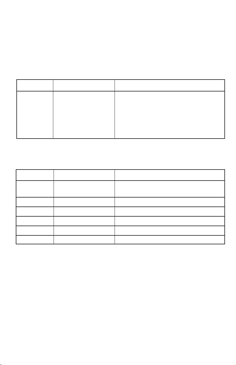
1. Description of the X-ray
system
a) X-ray Tubehead/Tubehead
Assembly
b) Dial, angulation
c) Timer/Wall-mount pivot assembly
d) Hand held control
e) Double-jointed scissors arm
f) Extension arm
g) Focal spot location
(Wall mounting plate
not shown)
2. Description of the hand held
X-Mind control unit
a) Display, Film sensitivity (1 to 9) or
Xray tubehead selected (A or B)
b) Patient’s jaw size selection
c) Warning light, X-ray emissions
d) Button, Exposure start
e) Upper and lower cat selections
f) Paw select
g) Exotic select
h) Upper dental arch (for dogs)
i) Exposure time display
j) Lower dental arch (for dogs)
k) “Ready” light, pre X-ray emission
l) Service test control
m) Film/Sensor sensitivity level
(Scroll button)
A2. Description of the Image-Vet 70ACP X-ray equipment
a
c
d
e
f
b
g
12
c
d
e
f
i
j
a
b
m
l
k
h
g
10
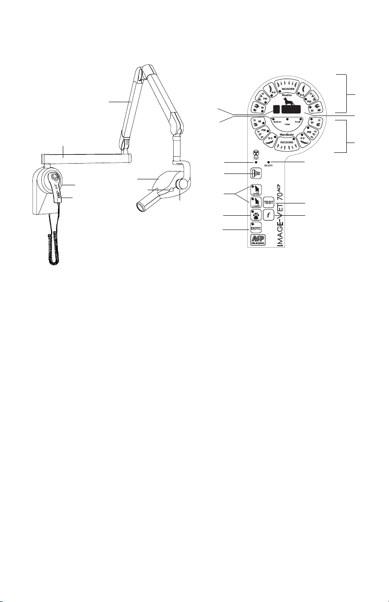
X-RAY EMISSION
SWITCH
WARNING LABEL
MAIN ON/OFF
SWITCH
IDENTIFICATION/CERTIFICATION
LABEL (TIMER CONTROL)
IDENTIFICATION/CERTIFICATION
WARNING LABEL (TUBEHEAD)
HAND CONTROLLER
ATTACHES HERE
Double-jointed scissors arm
This is a double-jointed arm which carries the
X-ray tubehead. It can be extended or retracted
and moved up and down while keeping the tube-
head balanced in the position it has reached. An
additional extension arm is attached to the arm
which is available in three different lengths: 15.75
in (40 cm), 23.6 in (60 cm) or 34.25 in (87 cm).
Micro-processor X-Mind control
panel
The microprocessor-based control system is used
to automatically set the exposure time from a
minimum of 0.02 s to a maximum of 1.28 s. The
electronic controller automatically determines
the exposure time according to the changes in
the electrical supply and in relation to the rated
voltage (in the range of + 10%).
X-ray tubehead with collimator
The X-ray tubehead is self-contained and due
to its operating characteristics, the exposure
time can be reduced so that less radiation
is absorbed by the patient. Moreover, the
tubehead is provided with a positioning cone
capable of operating at a minimum skin/focus
distance of 7.88 in (20 cm); the maximum
diameter of the X-ray beam is 2.36 in (6 cm).
The X-ray tubehead is attached to the arm in
such a way as to permit unlimited rotation. With
this arrangement it can be rotated 360° on its
horizontal plane while the rotary movements on
the vertical plane are limited by the positioning
cone.
POSITIONING CONE

11
A2.1. Nameplates
(1) X-ray tubehead nameplate
The name plate is located on the back of the
tubehead. The following details are given on
the name plate:
· Manufacturer
· Name of equipment
· Serial number
· Tube insert number
· Specifications
· Month and Year of manufacture
(2) X-Mind control unit nameplate
This plate is located on the left side of the controller.
The following details are given:
· Name of equipment
· Serial number
· Specifications
· Month and Year of manufacture
(3) X-Mind control warning nameplate
The nameplate is on the right side of the timer.
(4) Scissors & Extension Arms
These nameplates contain:
· Model number
· Serial number
1
2
3WARNING:
THIS X-RAY UNIT MAY BE DANGEROUS TO
THE PATIENT AND OPERATOR UNLESS
SAFE EXPOSURE FACTORS AND OPERAT-
ING INSTRUCTIONS ARE OBSERVED.
ELECTRICAL SHOCK HAZARD - DO NOT
REMOVE PANELS.
RISK OF EXPLOSION - DO NOT USE IN
PRESENCE OF FLAMMABLE
ANESTHETICS. FOR CONTINUED PROTEC-
TION AGAINST RISK OF FIRE, REPLACE
ONLY WITH SAME TYPE AND RATING
OF FUSE.
DANGER:
RISQUE D’ EXPLOSION - NE PAS EMPLOY-
ER IN PRESENCE D’ ANESTHETIQUES
INFLAMMABLES.
POUR ASSURER PROTECTION CON-
TINUE CONTRE LE RISQUE D’ INCENDIE.
UTLISER UNIQUEMENT UN FUSIBLE DE
RECHANGE DE MEME TYPE ET DE MEMES
CARACTERISTIQUES NOMINALES.
4
Model:
S/N:
12
90˚
A3. Basic applications of the Image-Vet 70ACP
A3.1. Basic patient position
The patient should be positioned on the table in whatever position that is
appropriate for the radiograph to be taken.
A3.2. Positioning the X-ray tubehead assembly
Position the tubehead by moving the double-jointed scissors arm so as to
bring the collimator into contact with the patient’s skin at the point where the
radiograph is to be made. The X-ray tubehead is set to the correct position
by using the bisecting angle technique
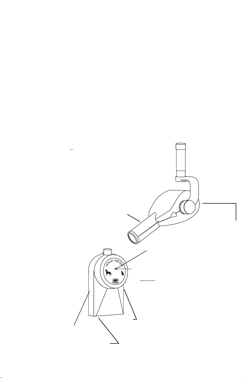
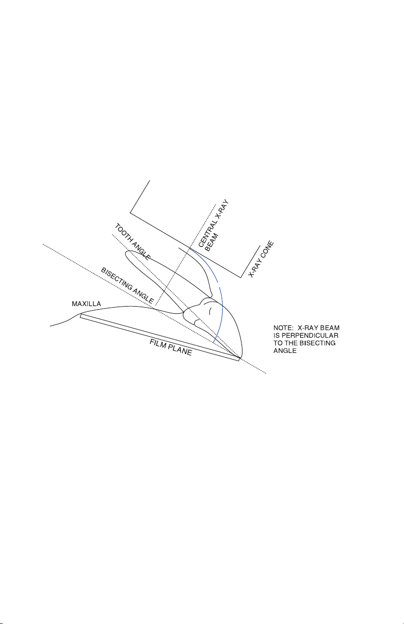
A3.2.1. Bisecting angle technique
a) Vertical incidence angle of the main beam:
In order to obtain a precise image of the tooth, the main beam must be
perpendicular to the bisector of the angle created between the longitudinal
axis of the tooth and of the film. Having positioned the tube head and the
film, as said above, an average incidence angle can be used for each area.
The incidence angle of the main beam can be determined by using the
graduated scale located on the bracket of X-ray tube. The diagram at the
side shows an example of positioning the X-ray cone using the bisecting
technique.
A3.2.2. Interproximal radiographs
To carry out this type of radiograph, the tubehead must be perpendicular
to the surface of the film.
13
EXPOSE
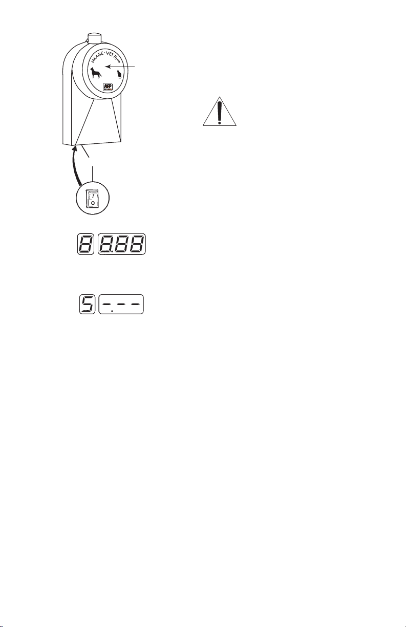
A3.3. Turning on the X-Mind control
Use the main switch (a) to turn ON the control
unit. The green light built into the switch will
come ON to indicate that power is being
delivered to the control unit.
IMPORTANT
Each time the unit is turned ON,
the equipment runs a test which
lasts 10 seconds. During this time,
no radiographs will be produced.
All the indicator lights come on and “8 8.88”
will be temporarily shown on the display.
A3.3.1. Display status
After the equipment is turned on and the initial test
has run, the display shows the selected sensitivity
for the film.
A3.4. Factory settings
Factory settings are determined
when the equipment is installed and
can only be modified by AFP Imaging Corp.
authorized technicians.
Always prepare before exposure with
appropriate protective shields, aprons
or equivalent devices to protect from
unnecessary radiation.
a

14
Typical Wall Mounting
Typical Mobile Mounting

15
EXPOSE
S
A3.5. Setting the exposure time
To set the radiation exposure time, the following
operations must be carried out:
· Press the key corresponding to the type of dog
tooth being radiographed. Otherwise press the key
for upper or lower cat jaw radiographs or the ones
for paw or exotic radiographs. The light built into
the key that has been pressed will light-up.
· Press the key which corresponds to the jaw or
part size of the patient. i.e.
a Small or light jaw
b Medium or average jaw (default)
c Heavy or dense jaw
· Set the sensitivity level for the film used (see page
16) by using the (f) key.
WARNING!
The green Ready light comes on to
indicate that the equipment is ready
for emitting X-rays.
· Move to a shielded or safe location
before exposure. Use caution in
the area where the X-rays are to be
emitted. Press the exposure control button
and hold it down. The yellow light will come on
together with an audible warning device which will
continue sounding until the X-ray emission has
been completed.
IMPORTANT!
SAFETY FEATURE
The exposure control button must be
held down during the entire exposure!
If the button is released prematurely,
X-ray emission is interrupted and the
radiograph may be underexposed.
Film Sensitivity
Select
X-Mind Hand Held Selector
X-ray Exposure
Start

16
Tooth Selections Small Medium Large
Patient Patient Patient
UPPER INCISORS 0.10 0.12 0.13
UPPER CANINES 0.22 0.25 0.28
UPPER PREMOLARS 0.17 0.20 0.23
UPPER MOLARS 0.17 0.20 0.23
LOWER MOLARS 0.13 0.15 0.17
LOWER PREMOLARS 0.13 0.15 0.17
LOWER CANINES 0.17 0.20 0.23
LOWER INCISORS 0.08 0.10 0.12
CAT (UPPER) 0.13 0.15 0.17
CAT (LOWER) 0.08 0.10 0.12
PAW 0.30 0.35 0.40
EXOTIC 0.08 0.10 0.12
A3.5.1. Exposure time chart
This chart shows the exposure time (in
seconds) for radiographs with a film
sensitivity of 4and the equipment running
at the rated voltage.
The first column indicates the type of teeth
or radiograph.
The second column indicates the exposure
time for animals with light jaws, the third
the exposure time for animals with medium
or average jaws, and the fourth that for
animals with large or dense jaws. Small,
Medium and Large Patient settings also
apply to parts radiographed with the PAW
and EXOTIC settings.
Selecting film sensitivity with the key:
NOTE: A setting of 2 - 3 for film sensitivity is a good range for
Kodak Insight (F) speed film OR the EVA-Vet Digital Imaging
System. A setting of 6 - 8 for film sensitivity is a good range for
Kodak Ultra-Speed (D) speed film.

17
EXPOSE
S
NOTE: All upper and lower tooth selections are for
dogs only. Due to the relatively small dentition of cats,
only the selection for any upper or maxillar feline tooth
(CAT UPPER) or any lower or mandibular feline tooth
(CAT LOWER) is needed. The PAW setting is for any
paw that can be rediographed within the field size of
the cone. The EXOTIC setting is for bird wings, small
animal extremities, etc., that can be radiographed
within the field size of the positioning cone.
The above chart shows the amount of exposure
time variation for the different film sensitivity values
Radiograph-film correction chart
Sensitivity Standard Variation
coefficient
1 0.500 - 50 %
2 0.630 - 37 %
3 0.800 - 20 %
4 1.000 0%
5 1.250 + 25 %
6 1.600 + 60 %
7 2.000 + 100 %
8 2.500 + 150%
9 3.200 +220%

18
A4. Film developing
A4.1 Automatic Processor
Automatic film processors designed for processing dental films with RP type chemicals (such as
the AFP 810 Plus or 810 Basic) control all of the processing parameters (such as temperature,
time, washing and drying) automatically. When set up and maintained properly, they will develop
the images with very little attention required by the operator.
A4.2Manual Hand Tank Processing
In order to obtain good quality images, the film must be developed by carefully following the
instructions below:
1.) Remove the film from the package in a dark room taking care not to damage it with
fingerprints or scratches. Use holder clips as required.
2.) Immerse the film in the developer and shake it for a few seconds then leave it for 5
minutes at a temperature of 68°F (20°C), 6 minutes at 66°F (18°C) or 4 minutes at
72°F (22°C).
3.) Rinse in running water for approx. 20 seconds. Immerse the film in the fixing agent,
shake it for a few seconds and leave it there for at least 5 minutes.
4.) Wash the film in running water. This operation and the ones that follow can be
performed outside the dark room. Dry the film in the open air away from dust.
5.) The slightest amount of fixer will contaminate the developer solution. Never move a
film from the fixer solution back into the developer solution.
It is extremely important to use fresh chemicals dispensed in the correct proportions. Do not add
developer to make the baths stronger as this increases contrast but reduces detail.
POSSIBILITIES
DEFECTIVE EXPOSURE DEVELOPING STATE OF THE POSITION
IMAGES TIME TIME BATHS
Underexposed Too short Too short Cold
Overexposed Too long Too long Hot
Lack of detail Too short Cold or depleted
Blurring or Patient moved during
double image exposure
Distorted Film bent during
exposure
Not centered incorrect angle
Teeth elongated Incidence angle of
center beam too
horizontal
Teeth shortened Incidence angle of
central beam too vertical
Too light or Fixing time
transparent too long
Not transparent Fixing time
enough too short
Table of contents


