Afriso EURO-INDEX Unitop AdBlue User manual
Version: 03.2017.0
ID: 900.000.0129
Lindenstraße 20
74363 Güglingen
Telefon+49 7135 102-0
Service+49 7135-102-211
Telefax +49 7135-102-147
www.afriso.com
Copyright 2017 AFRISO-EURO-INDEX GmbH. All rights reserved.
EN
Operating
instructions
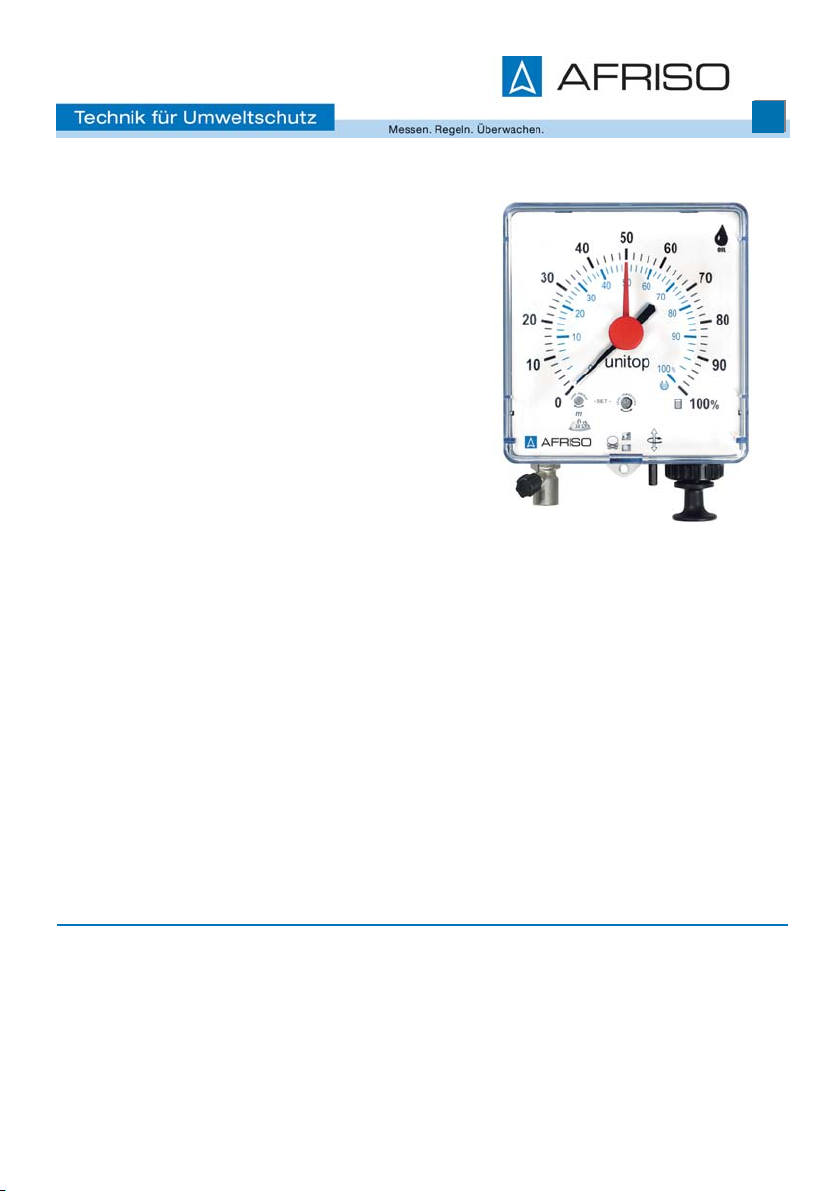
Pneumatic level indicator
Unitop
Unitop AdBlue®

2
About these operating instructions
EN
Unitop
1 About these operating instructions
These operating instructions describe the pneumatic level indicator "Unitop"
(also referred to as "product" in these operating instructions). These operat-
ing instructions are part of the product.
• You may only use the product if you have fully read and understood these
operating instructions.
• Verify that these operating instructions are always accessible for any type
of work performed on or with the product.
• Pass these operating instructions as well as all other product-related doc-
uments on to all owners of the product.
• If you feel that these operating instructions contain errors, inconsisten-
cies, ambiguities or other issues, contact the manufacturer prior to using
the product.
There operating instructions are protected by copyright and may only be
used as provided for by the corresponding copyright legislation. We reserve
the right to modifications.
The manufacturer shall not be liable in any form whatsoever for direct or con-
sequential damage resulting from failure to observe these operating instruc-
tions or from failure to comply with directives, regulations and standards and
any other statutory requirements applicable at the installation site of the prod-
uct.

3
Information on safety
EN
Unitop
2 Information on safety
2.1 Safety messages and hazard categories
These operating instructions contain safety messages to alert you to poten-
tial hazards and risks. In addition to the instructions provided in these oper-
ating instructions, you must comply with all directives, standards and safety
regulations applicable at the installation site of the product.Verify that you are
familiar with all directives, standards and safety regulations and ensure com-
pliance with them prior to using the product.
Safety messages in these operating instructions are highlighted with warning
symbols and warning words. Depending on the severity of a hazard, the
safety messages are classified according to different hazard categories.
NOTICE
NOTICE indicates a hazardous situation, which, if not avoided, can
result in equipment damage.

4
Information on safety
EN
Unitop
2.2 Intended use
Unitop 3000 part no. 28000
This product may only be used for measuring the level of the following media:
• Fuel oil EL as per DIN 51603-1
• Diesel fuel as per EN 590
• Fatty acid methyl ester (FAME) as fuel oil as per EN 14213
• Fatty acid methyl ester (FAME) as biodiesel as per EN 14214
• Flammable liquids of danger class A III and non-flammable liquids with
the following prerequisites:
- The vapours of the liquids do not attack plastic materials (PA, PS, PE),
Cu, Zn and Sn alloys and elastomers.
- The liquid does not belong to danger classes AI, AII or B.
- Cinematic viscosity < 300 mm²/s.
Unitop AdBlue®part no 28042
This product may only be used for measuring the level of AdBlue®as per DIN
70070 with a specific weight (density) = 1090 kg/m³. The term AdBlue® des-
ignates the same as "NOx reduction agent AUS 32" and "urea solution 32.5
%").
Any use other than the application explicitly permitted in these operating
instructions is not permitted and causes hazards.
Verify that the product is suitable for the application planned by you prior to
using the product. In doing so, take into account at least the following:
• All directives, standards and safety regulations applicable at the installa-
tion site of the product
• All conditions and data specified for the product
• The conditions of the planned application
In addition, perform a risk assessment in view of the planned application,
according to an approved risk assessment method, and implement the
appropriate safety measures, based on the results of the risk assessment.
Take into account the consequences of installing or integrating the product
into a system or a plant.
When using the product, perform all work and all other activities in conjunc-
tion with the product in compliance with the conditions specified in the oper-
ating instructions and on the nameplate, as well as with all directives, stand-
ards and safety regulations applicable at the installation site of the product

5
Information on safety
EN
Unitop
2.3 Predictable incorrect application
The product must never be used in the following cases and for the following
purposes:
• Hazardous area (EX)
- If the product is operated in hazardous areas, sparks may cause defla-
grations, fires or explosions.
• Level measurement of liquids not specified above.
• Use of the measurement result for billing purposes.
2.4 Qualification of personnel
Only appropriately trained persons who are familiar with and understand the
contents of these operating instructions and all other pertinent product doc-
umentation are authorized to work on and with this product.
These persons must have sufficient technical training, knowledge and expe-
rience and be able to foresee and detect potential hazards that may be
caused by using the product
All persons working on and with the product must be fully familiar with all
directives, standards and safety regulations that must be observed for per-
forming such work.
2.5 Personal protective equipment.
Always wear the required personal protective equipment. When performing
work on and with the product, take into account that hazards may be present
at the installation site which do not directly result from the product itself.
2.6 Modifications to the product
Only perform work on and with the product which is explicitly described in
these operating instructions. Do not make any modifications to the product
which are not described in these operating instructions.

6
Transport and storage
EN
Unitop
3 Transport and storage
The product may be damaged as a result of improper transport or storage.
NOTICE
DAMAGE TO THE PRODUCT
• Verify compliance with the specified ambient conditions during transport or
storage of the product.
• Use the original packaging when transporting the product.
• Store the product in a clean and dry environment.
• Verify that the product is protected against shocks and impact during trans-
port and storage.
Failure to follow these instructions can result in equipment damage.

7
Product description
EN
Unitop
4 Product description
The product measures the hydrostatic pressure at the tank bottom to deter-
mine the level. The hydrostatic pressure depends on the level and the density
of the stored liquid. The pressure is measured approximately 20 mm above
the tank bottom and indicated on the dial.
Pneumatic pressure is generated in the pressure line by pulling out and push-
ing back the pump plunger. The pressure line consists of the measuring line
(from the measuring instrument to the tank) and the vertical line (inside the
tank). The pneumatic pressure displaces the liquid from the vertical line.
When the pneumatic pressure is equal to the hydrostatic pressure acting at
the tank bottom, the liquid is fully displaced from the vertical line. Bubbles
start to escape at the lower end of the vertical line. In this condition, the
pointer has reached the maximum deflection and remains at the indicated
value.
The product enables consumption monitoring and timely re-fuelling. The tank
lorry driver can use the product to verify prior to filling whether the ordered
volume fits into the tank.
It is recommended to use the mounting kit Pneumofix type 2, see chapter
"Spare parts and accessories".
8
Product description
EN
Unitop
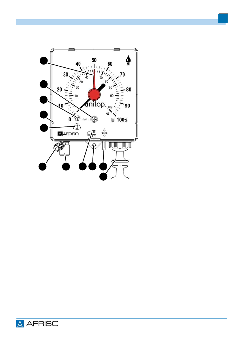
4.1 Overview
A. Red reference pointer
B. Adjustment screw for zero
correction
C. Adjustment screw for
measuring range
D. Support for additional
slide-in scale
E. Adjustment scale for
measuring range
F. Vent cap
G. Connection for measuring
line
H. Manual date indicator
I. Lug
J. Adjustment pin for date
indicator
K. Pump plunger
A
D
C
B
GH
E
IJ
K
F

9
Product description
EN
Unitop
4.2 Dimensions
166 mm
205 mm
281 mm

10
Product description
EN
Unitop
4.3 Technical specifications
Parameter Value
General specifications Unitop 3000 Unitop AdBlue®
Dimensions housing (W x
HxD) 155 x 166 x 73 mm
Weight 0.6 kg
Housing Plastic, ABS
Window Plastic SAN
Measuring system Brass
Measuring range
Fully adjustable 900 to 3000 mm tank
height 700 to 2300 mm tank
height
Measuring accuracy ±2 % of full scale value
Indication Standard: 0-100 % liquid level for rectangular and
cylindrical horizontal tanks, additional scales with
litre indication for standardised tanks and special
additional scales
Operating temperature range
Ambient -5/+55 °C
Storage -5/+55 °C
Vertical line (wetted)
Material The vertical line must consist of a material that is
neutral with regard to the medium
For example, for fuel oil EL, diesel fuel and FAME:
Pneumofix line (PVC), copper pipe or oil-resistant
Perbunan-N hose with weight as spacer
Inside diameter 4 mm for fuel oil EL, L, M, diesel fuel, FAME, liq-
uids with a kinematic viscosity up to 90 mm²/S
6 mm liquids with a kinematic viscosity up to
190 mm²/S
8 mm liquids with a kinematic viscosity up to
300 mm²/S
Measuring line

11
Product description
EN
Unitop
Length Max. 50 m
Version - Copper pipe 6 mm (outside Ø) x 1 mm
- PVC hose 4 mm (inside Ø)x1mm
- PE hose 4 mm (inside Ø)x1mm
Approved media Unitop 3000 Unitop AdBlue®
Medium Fuel oil EL or diesel fuel
(density = 0.84 g/cm³ at
+15°C)
AdBlue®
Parameter Value

12
Mounting
EN
Unitop
5 Mounting
5.1 Mounting the product
Verify that the housing is accessible and easy to oversee at all times.
Verify that the housing is protected against water and splash water.
Verify that the housing is not mounted in a humid room.
Verify that the ambient temperature is not exceeded at the housing.
Verify that the housing is protected from direct sunlight.
1. Drill two holes at the same height at a distance of 13 cm.
- Use the enclosed drilling template.
2. Insert the enclosed dowels.
3. Screw in the screws up to approx. 1.5 cm.
4. Fit the product onto the screws and slightly pull it down.
- The lug is flush with the wall.
5. Fasten the product to the wall by means of the third screw.
5.2 Adjusting the measuring range and calibrating the zero point
The measuring range and the zero point must be accurately adjusted for the
product to operate with maximum measuring accuracy.
Verify that the measuring
line has not yet been con-
nected or open the vent
cap (A). The system must
be unpressurised.
A

13
Mounting
EN
Unitop
1. Determine the measuring
range.
- Fuel oil EL and diesel
fuel: Measuring range =
tank height.
- Other liquids: See table
"Determining the meas-
uring range"
1. Open the window (A) by
means of a screwdriver.
2. Adjust the measuring
range (B) by means of an
Allan key.
3. Slightly tap at the side of
the housing
4. Correct the zero point (C)
by means of a screw-
driver.
5. Set the pointer to "0" by
means of a screwdriver.
Do not turn to the right or
left by more than 1 turn.
6. Insert the additional scale,
if applicable.
7. Close the window (A).
A
C
B

14
Mounting
EN
Unitop
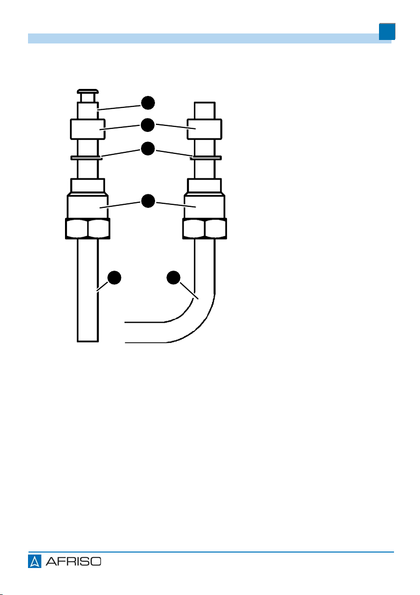
5.3 Mounting the line
If no connection thread is available on the tank, several lines can be con-
nected via the combination fitting "Euroflex 3" to a single G1 connection
thread.
1. Mount the vertical line in the tank in such a way that the lower end of the
vertical line is approximately 20 mm above the lowest point of the tank bot-
tom.
2. Install the measuring line with a steady gradient towards the tank, avoid
bends.
3. Push the screw connection onto the measuring line.
A. Unitop
B. Measuring line
C. Standpipe
D. Condensate trap
A
C
B
D
15
Mounting
EN
Unitop
If the measuring line does not have a steady gradient to the tank or if conden-
sate can collect in the measuring line, use a condensate trap.
1. Push the measuring line into the connection piece all the way to the stop.
2. Slightly tighten the compression screw.
3. Connect the vertical line and the measuring line.
A. Hollow rivet
B. Seal
C. Washer
D. Compression screw
E. Hose
F. In-line
A
B
D
C
F
E

16
Operation
EN
Unitop
6 Operation
Precise measurements are not possible during filling of the tank. The
pointer does not provide a stable reading during filling.
Verify that the vent cap is closed.
The product provides semi-permanent indication. The pump closes off the
measuring line when it reaches the upper dead end. The pointer stays tem-
porarily at its last reading and then drops back very slowly. As a result of this,
the gauge mechanism is protected by an air cushion.
1. Pull out the pump plunger all the way to the stop.
2. Then release the pump plunger.
3. Repeat the pumping procedure until the indicated value no longer
changes.
4. Read the level on the scale.
- If the measuring line has been installed airtight, the pointer of the gauge
will continue to show the last reading for a long period of time. In order
to obtain an accurate reading, always operate the pump before a read-
ing is taken.
The red reference pointer can be adjusted manually, for example to the level
after the last filling. The red reference pointer lets you compare the current
level to a previous level for consumption monitoring. The date indicator can
be adjusted manually, for example, in order to mark the date of the most
recent tank filling.
6.1 Setting the day
1. Push the adjustment pin to the top and turn it.
6.2 Setting the month
1. Push the adjustment pin down and turn it.
6.3 Use in flood hazard areas
The product is suitable for use in flood hazard areas; it is watertight up to 10
m water column (1 bar pressure).
The product does not have to be replaced after a flood.

17
Maintenance
EN
Unitop
7 Maintenance
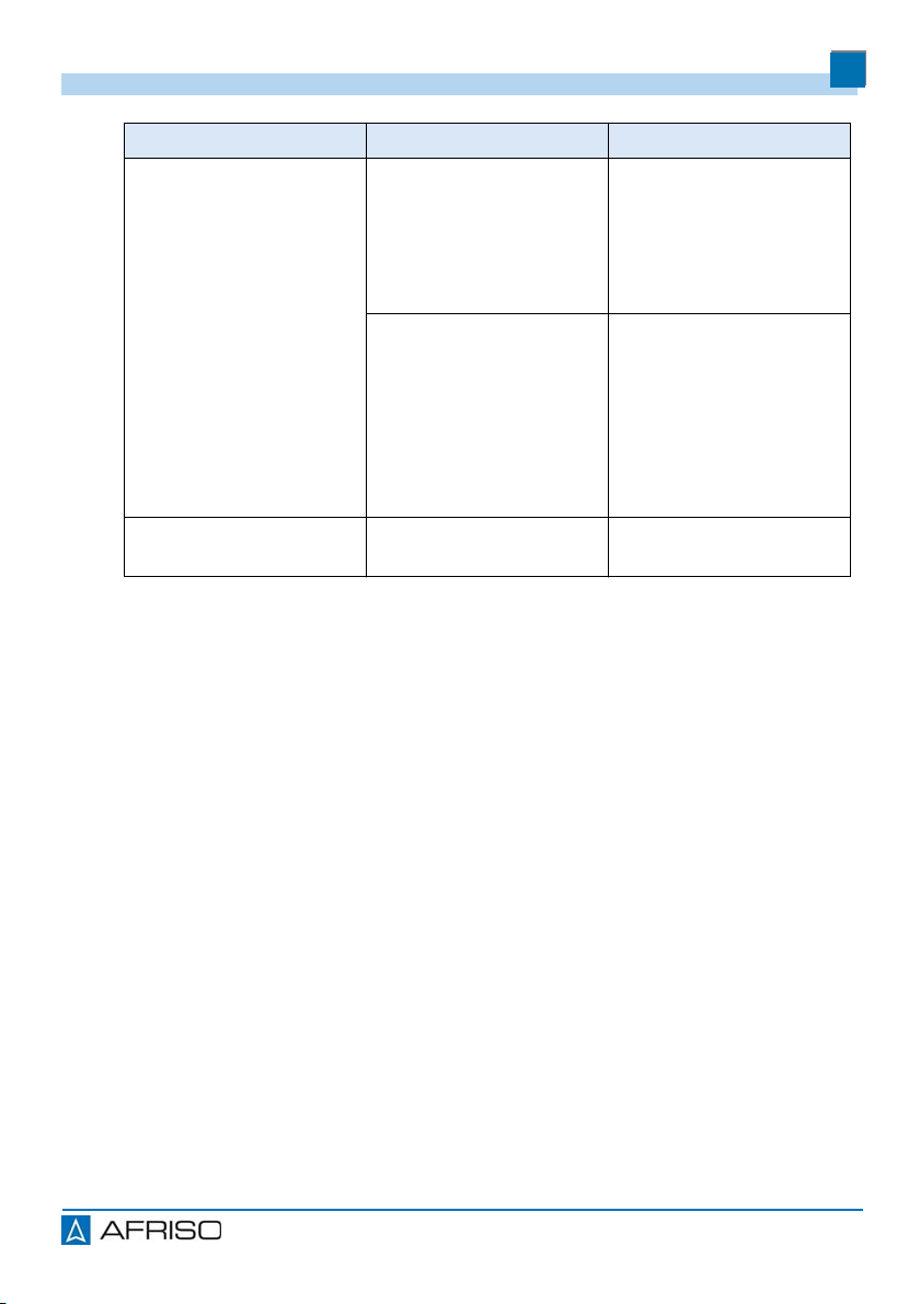
7.1 Maintenance intervals
Perform a function test at least once per year.
When Activity
Water in condensate
trap Drain the condensate trap.
During tank mainte-
nance and/or tank
cleaning
Verify correct operation of the product and have
the product re-adjusted, if necessary.

18
Troubleshooting
EN
Unitop
8 Troubleshooting
Any malfunctions that cannot be removed by means of the measures
described in this chapter may only be repaired by the manufacturer or by
qualified persons.
Problem Possible reason Repair
Pointer does not move
when pump is operated
or drops back very
quickly
Connections or lines
have a leak. Seal the connections
and lines.
Tank is being filling. Measure the level after
filling the tank.
Pointer goes beyond
100 % or pump plunger
does not fully return.
Measuring line clogged
or bent. Make sure there are no
bends in the measuring
line.
Install a condensate
trap.
Condensate trap full. Drain the condensate
trap.
Measuring range not
correctly adjusted. Verify and correct the
adjusted values (see
chapter "Adjusting the
measuring range and
calibrating the zero
point").
19
Troubleshooting
EN
Unitop
Problem Possible reason Repair
Incorrect indication Incorrect measuring
range
adjusted.
Verify and correct the
adjusted values (see
chapter "Adjusting the
measuring range and
calibrating the zero
point").
Incorrect zero adjust-
ment. Remove the pressure
from the system by
opening the vent cap.
Correct the zero point,
see chapter "Adjusting
the measuring range
and calibrating the zero
point".
Other malfunctions - Contact the AFRISO
service hotline.

20
Decommissioning, disposal
EN
Unitop
9 Decommissioning, disposal
Dispose of the product in compliance with all applicable directives, standards
and safety regulations.
1. Dismount the product (see chapter "Mounting", reverse sequence of
steps).
2. Dispose of the product.
10 Returning the device
Get in touch with us before returning your product.
11 Warranty
See our terms and conditions at www.afriso.com or your purchase contract
for information on warranty.
This manual suits for next models
1
Table of contents
Other Afriso EURO-INDEX Touch Panel manuals

Popular Touch Panel manuals by other brands

Contro l4
Contro l4 C4-TSWM7-E-B Technical specifications

Contro l4
Contro l4 C4-TSWM10-E-W installation guide

Saia Burgess Controls
Saia Burgess Controls PCD7.D412DTPF manual

EL GENS
EL GENS LPC P-cap Series user manual

Contro l4
Contro l4 C4-TSWMC5-EG-WH installation guide

Contec
Contec IPC-PT/MV10 Series Software manual


