Afriso EURO-INDEX DIT 01-E User manual

Read instructions before using device!
Observe all safety information!
Keep instructions for future use!
Version: 05.2011 0
ID no.: 854.001.0335
Mess-, Regel- und
Überwachungsgeräte
für Haustechnik,
Industrie und Umweltschutz
Lindenstraße 20
DE-74363 Güglingen
Telefon: +49(0)7135-102-0
Service: +49(0)7135-102-211
Telefax: +49(0)7135-102-147
Internet:www.afriso.de
Operating Instructions
Digital Tank Contents Indicator
Type: DIT 01
DIT 01 Product No.: 52122
DIT 01-E Product No.: 52123

2 DIT 01
Contents
1About this manual....................................................................................................4
1.1 Precautions ..................................................................................................4
1.2 Explanation of symbols and typeface ..........................................................4
2Safety ......................................................................................................................5
2.1 Intended use ................................................................................................5
2.2 Predictable incorrect application..................................................................5
2.3 Safe handling ...............................................................................................5
2.4 Staff qualification..........................................................................................6
2.5 Modifications to the product.........................................................................6
2.6 Usage of spare parts and accessories.........................................................6
2.7 Liability information ......................................................................................6
3Product description..................................................................................................6
3.1 Design..........................................................................................................7
3.2 Scope of delivery..........................................................................................8
3.3 Function........................................................................................................9
4Specifications ..........................................................................................................9
4.1 Approvals, tests and conformities..............................................................11
5Transportation and storage...................................................................................11
6Mounting and commissioning................................................................................12
6.1 Tank data determination ............................................................................12
6.2 Mounting the wall holder............................................................................13
6.3 Mounting the junction box..........................................................................13
6.4 Cable connection .......................................................................................13
6.5 Connecting the battery...............................................................................14
6.6 Zero balancing ...........................................................................................14
6.7 Mounting the pressure sensor....................................................................15
6.8 Entering the tank data................................................................................18
7Operation...............................................................................................................20
7.1 Switching on and off...................................................................................20
7.2 Display formats ..........................................................................................20
7.3 Correct tank data........................................................................................20
7.4 Subsequent zero balancing........................................................................21
8Maintenance..........................................................................................................21
8.1 Maintenance times.....................................................................................21
8.2 Replacing the battery.................................................................................21
9Troubleshooting.....................................................................................................21
10 Shutting down and disposal ..................................................................................22

11 Spare parts and accessories.................................................................................23
12 Warranty................................................................................................................23
13 Copyright ...............................................................................................................23
14 Customer satisfaction............................................................................................23
15 Adresses................................................................................................................24
DIT 01 3

About this manual
1 About this manual
This instruction manual is part of the product.
Read this manual before using the product.
Keep this manual during the entire service life of the product
and always have it readily available for reference.
Always hand this manual over to future owners or users of the
product.
1.1 Precautions
WARNING TERM
Type and source of the danger is shown here.
Precautions to take in order to avoid the danger are shown
here.
There are three different levels of warnings:
Warning term Meaning
DANGER Immediately imminent danger!
Failure to observe the information will result in
death or serious injuries.
WARNING Possibly imminent danger!
Failure to observe the information may result in
death or serious injuries.
CAUTION Dangerous situation!
Failure to observe the information may result in
minor or serious injuries as well as damage to
property.
1.2 Explanation of symbols and typeface
Symbol Meaning
Prerequisite for an activity
Activity consisting of a single step
1. Activity consisting of several steps
Result of an activity
• Bulleted list
Text Indication on a display
Highlighting Highlighting
4 DIT 01

Safety
2 Safety
2.1 Intended use
The DIT 01 digital tank contents indicator is exclusively suitable for
the measurement of filling levels in heating oil tanks with heights up
to 3 metres.
Any use other than the use explicitly permitted in this instruction ma-
nual in not permitted.
2.2 Predictable incorrect application
The DIT 01 digital tank contents indicator must never be used in the
following cases:
• Hazardous areas (ex)
2.3 Safe handling
The DIT 01 digital tank contents indicator represents state-of-the-art
technology and is made according to the pertinent safety regulations.
Each device is subjected to a function and safety test prior to ship-
ping.
Operate the DIT 01 digital tank contents indicator only when it is
in perfect condition. Always observe the operating instructions,
all pertinent local and national directives and guidelines as well
as the applicable safety regulations and directives concerning
the prevention of accidents.
The DIT 01 digital tank contents indicator is not a safety device.
It does not replace the function of a limit value transducer at the
heating oil tank.
The DIT 01 digital tank contents indicator may only be installed
in unpressurised heating oil tanks. A tank vent installed in ac-
cordance with the pertinent regulations as well as a limit value
transducer are required.
The cable entry point of the pressure sensor into the heating oil
tank must be significantly higher than the maximum filling level
and must be sealed with the enclosed screw connections in
such a way that no oil vapours can escape and that the pres-
sure sensor cannot move vertically
The measured values displayed, especially the litre indication
values, must not be used for billing purposes. The accuracy of
the measured values displayed depends on the accuracy of the
tank data determined and entered. Therefore, the manufacturer
cannot guarantee the accuracy required for billing purposes.
DIT 01 5

Product description
Extreme environmental conditions have negative effects on the func-
tion of the product.
Protect the DIT 01 from shocks.
Only use the digital unit in rooms.
Protect the digital unit from humidity.
2.4 Staff qualification
The product may only be mounted, commissioned, operated, main-
tained, shut down and disposed of by qualified, specially trained
staff.
Electrical work may only be performed by trained electricians quali-
fied in accordance with the local and national directives.
2.5 Modifications to the product
Changes or modifications made to the product by unauthorised per-
sons may lead to incorrect readings and are prohibited for safety
reasons.
2.6 Usage of spare parts and accessories
Usage of unsuitable spare parts and accessories may cause dam-
age to the product.
Use only genuine spare parts and accessories of the manufac-
turer (refer to chapter 11, page 23).
2.7 Liability information
The manufacturer shall not be liable for direct or consequential dam-
age resulting from failure to observe the technical instructions, guide-
lines and recommendations.
The manufacturer and the sales company shall not be liable for costs
or damages incurred by the user or by third parties in the usage or
application of this device, in particular in case of improper use of the
device, misuse or malfunction of the connection, malfunction of the
device or of connected devices. The manufacturer or the sales com-
pany shall not be liable for damages resulting from any use other
than the use explicitly permitted in this instruction manual.
The manufacturer shall not be liable for misprints.
3 Product description
The DIT 01 digital tank contents indicator consists of an electronic
pressure sensor and a microprocessor-controlled digital unit con-
tained in a sturdy plastic housing. The measured values are shown
on a 4-digit liquid crystal display (LCD). The function key F allows
you to switch on the device and select the display modes litres, cubic
6 DIT 01
Product description
metres, percentage and filling level. The device is programmed via
the two keys . A lithium battery is contained in the housing of the
digital unit. The battery is not connected when the device is shipped.
The free end of the cable is connected to the pressure sensor. The
pressure sensor and the digital unit form one unit. The pressure sen-
sor is placed in the tank from the top and is mounted either with a
connection and sealed.
The pressure sensor includes a spacer so that the measuring hole of
the pressure sensor remains above the oil sludge level.
Different screw connections are shipped with the pressure sensor
which are used to mount the pressure sensor cable to the tank and
seal it.
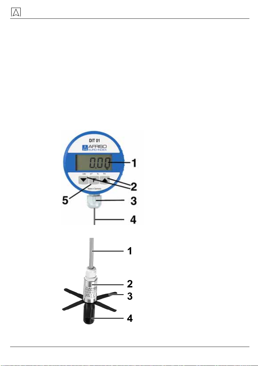
3.1 Design
1 Display
2 Programming keys
3 PG screw connec-
tion
4 Cable
5 Function key
Fig. 1: Digital unit
1 Cable with vent tube
2 Pressure sensor
3 Star
4 Spacer
Fig. 2: Pressure sensor with spacer
DIT 01 7
Product description
3.2 Scope of delivery
• Digital unit
• Pressure sensor with spacer
• Moisture-proof junction box
• Insulating screw joint, 4 poles
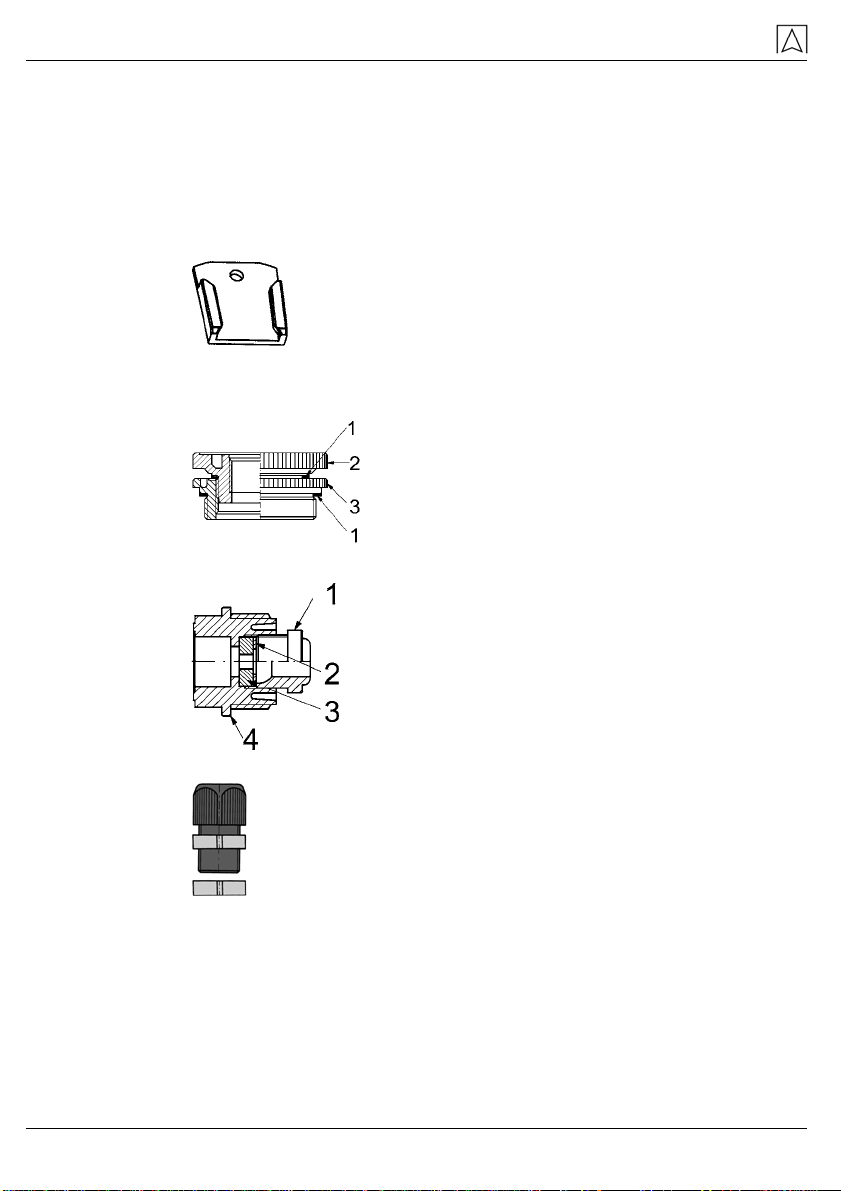
• Wall holder for DIT 01:
Screw connection DIT 01
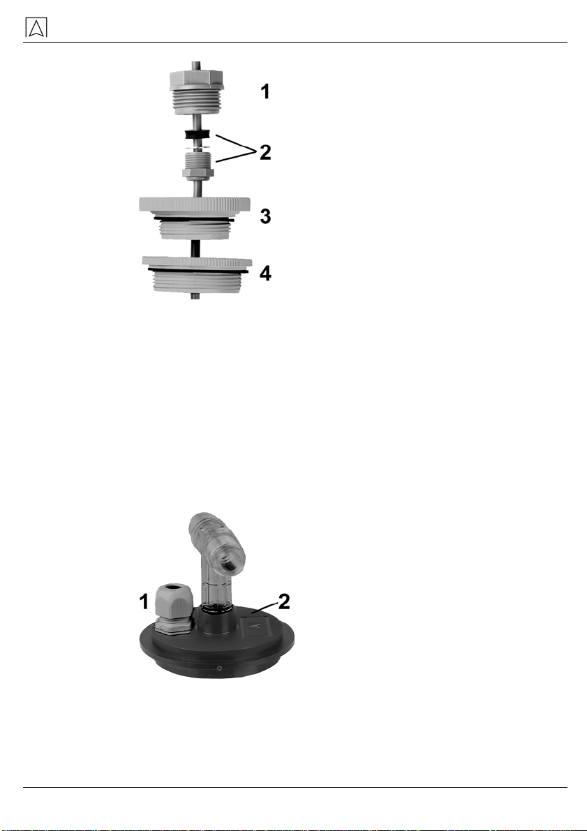
• Connection set 2" x 1½" x 1":
1 Flat packing NBR
2 Adapter G1½ - Rp1
3 Adapter G2 - G1½
• Screw connection 1":
1 Gland
2 Washer Ø 17
3 Plug
4 Screw fitting
• Connection PG9 with hex nut:
8 DIT 01

Specifications
Connection DIT 01-E
• Euroflex combination withdrawal fitting with 3.1 m suction tube,
2 O rings (6.5 x 1.5 mm) and pressure screw:
3.3 Function
The pressure sensor is located at the lowest point of the heating oil
tank and transforms the hydrostatic pressure of the heating oil into
an electrical signal. The measuring signal is transmitted to the digital
unit via the cable. The electronic system of the digital unit uses this
signal to calculate the tank contents, which it displays in litres, cubic
metres, percentage or filling level. The display mode is selected by
means of the F function key. The tank data is entered via the two
programming keys.
4 Specifications
Table 1: Digital unit
Parameter Value
General
Dimensions (ø x L) 75 x 50 mm
Weight 380 g
Cable length 5 m
Housing material PA6 15 % glass ball reinforced
Power supply 3,6 V lithium battery
Battery life Max. 8 years (pressing the F key 1 x
per month)
Display 4-digit LCD
DIT 01 9

Specifications
10 DIT 01
Parameter Value
Resolution 14 bit
Measuring input 0-3,6 V
Accuracy* < ± 1,0 % FSO, IEC 60770
Operating temperature range
Ambient 0 °C to +45 °C
Storage -5 °C to +80 °C
Electrical safety
Protection IP 51 EN 60529
Electromagnetic compatibility (EMC)
Noise suppression According to EN 50081-1
Noise immunity According to EN 50082-1
Table 2: Pressure sensor
Parameter Wert
General
Dimensions (ø x L) 25 x 107 mm
Weight 410 g
Cable length 5 m
Pressure range 0-300 mbar
Accuracy* < ± 1,0 % FSO, IEC 60770
Temperature error < ± 2 % FSO, 0-60 °C
Material
Housing Stainless steel 1.4305
Cable Heating oil-resistant PVC
Spacer POM, PE
Additional parts coming
into contact with the me-
dium
Ceramiks, silicon, silicone glue, Viton
Operating temperature range
Medium 0 °C to +60 °C
Transportation and storage
DIT 01 11
Parameter Wert
Storage -5 °C to +80 °C
Electrical safety
Protection IP 68 EN 60529
Electromagnetic compatibility (EMC)
Noise suppression According to EN 50081-2
Noise immunity According to EN 50082-2
Accuracy of complete system*: < ± 1,5% FSO, IEC 60770
* With reference to the filling level indication in mm.
4.1 Approvals, tests and conformities
The device meets complies with the European directive Electromag-
netic compatibility (89/336/EEC and 92/31/EEC).
5 Transportation and storage
CAUTION
Damage to the device due to improper transportation.
Do not throw or drop the device.
CAUTION
Damage to the device due to improper storage.
Protect the device against shock when storing it.
Store device in a clean and dry environment.
Store device only within the admissible temperature range.

Mounting and commissioning
6 Mounting and commissioning
6.1 Tank data determination
Before the DIT 01 tank contents indicator is installed, you must de-
termine the appropriate tank data. Please document the tank data on
this page for safety reasons and to allow for subsequent checks.
Tank shape
Refer to the table below to find the appropriate code for the tank
shape. If you want a linear indication, use the code 1.
Tank shape
code Tank shape Description
1 Linear tank Rectangular tanks, upright, cylin-
ders, steel tanks welded in base
ments, all other linear measuring
applications.
2 Tubular tank Vertical cylinder
3 Ball-shaped tank Ball-shaped tank
4 Plastic battery
tank Plastic battery tanks with armour-
ing or arches
5 Oval tank Oval basement tanks, e.g glass-
fibre reinforced tanksor steel
sheet tanks
6 Plastic tank with
recess Plastic tanks with major recess
major in the centre (manufactur-
ers: e.g. Roth, Werit)
Determined tank shape code:
Tank volume
Determine the total volume of the tank facility in litres.
Determined tank volume: litres
Tank height (max. filling level)
Determine the tank height in mm.
Determined tank height: mm
Current filling level
Determine the current filling level as exactly as possible in mm.
Determined filling level: mm
12 DIT 01

Mounting and commissioning
6.2 Mounting the wall holder
Use the enclosed screw (4 x 30 mm) and, if necessary, a dowel
(6 mm) to mount the wall holder for the DIT 01 tank contents in-
dicator at the desired location.
6.3 Mounting the junction box
The provided moisture-proof junction box is not suitable for exterior
application.
1. For exterior application use the exterior junction box, refer to
chapter 11, page 23.
2. Use the enclosed screws and, if necessary, dowels, to mount
the junction box for connecting the pressure sensor cable and
the cable of the digital unit at the desired location. Make sure to
provide sufficient cable length. The digital unit must be able to
be removed from the wall holder, e.g. if you need to replace the
battery.
2. Place the digital unit into the wall holder and route the cable into
the junction box.
3. Push the connection elements required for the tank connection
(PG connection, screw connection or Euroflex) onto the pres-
sure sensor cable in the correct sequence and orientation.
6.4 Cable connection
1. Route the cable of the pressure sensor to the junction box and
connect the two cables by means of the insulating screw joint.
Make sure to connect the wires of the same colour, respectively.
Digital unit
1 White (U+)
2 Green (signal)
3 Brown (U-)
4 Yellow/black (screen)
5 Insulating screw joints
6 Pressure sensor
7
Fig. 3: Cable connection
DIT 01 13
Mounting and commissioning
4. A transparent tube can be seen at the cable end of the pressure
sensor. This tube provides the pressure sensor with atmos-
pheric pressure. Make sure not to close or bend this tube in or-
der to avoid incorrect measurements.
The junction box must be closed in such a way that it is water-
tight but not completely airtight.
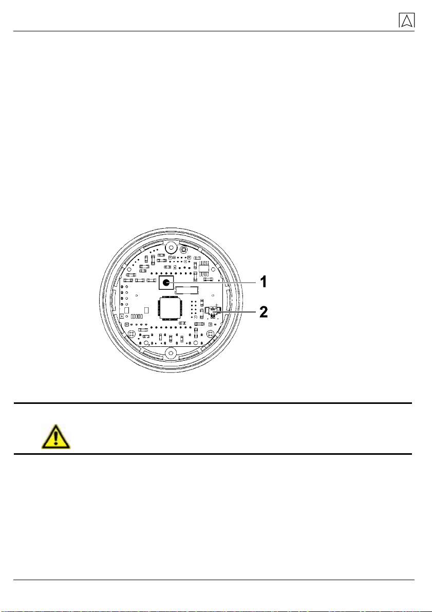
6.5 Connecting the battery
1. After you have electrically connected the pressure sensor and
the digital unit, open the housing of the digital unit by turning the
upper part of the housing all the way to the stop and pulling it
up.
5. Press the miniature button (1) and keep holding it down. Plug
the 2-pole battery plug into the 2-pole socket (2) on the printed
circuit board.
Miniature
button
1
2-pole socket
2
Fig. 4: Printed circuit board
WARNING
Danger of explosion in case of short circuit of the lithium bat-
tery.
Do not short-circuit the lithium battery.
6. Release the miniature button.
6.6 Zero balancing
1. Close the housing of the digital unit by pushing the two housing
parts together.
Since the battery was connected, the digital unit was switched on.
The display switches between "Zero" and the current offset of the
pressure sensor (indication in hPa = mbar). The top left corner of the
14 DIT 01

Mounting and commissioning
display shows the arrows to indicate that you are in calibration
mode.
7. Press the keys and simultaneously to correct the offset to
the value 0.00.
When you do this, the pressure sensor must not be in the
tank.
In this state, you can zero the system any number of times.
8. Press the F key in order to exit the zero balancing mode.
An arrow is shown at the bottom of the display pointing to the
unit Litres.
6.7 Mounting the pressure sensor
The unit is zeroed.
1. Plug the star onto the sensor, observe the position of the fins at
the star.
9. Screw the star to the probe by means og the spacer.
Spacer
1 Star
2 Pressure sensor
3
Fig. 5: Mounting the pressure sensor
10. Bend the arms of the star to the front.
11. Push the probe through the tank connection thread.
Fig. 6: Pushing the probe in the tank
DIT 01 15

Mounting and commissioning
12. Move the cable in the connection until the probe tip just reaches
the tank bottom. The measuring hole of the pressure sensor
must not be immersed in the oil sludge. The oil volume below
the level of the measuring hole is not detected by the pressure
sensor.
13. Insert the withdrawal hose after you have inserted the pressure
sensor.
Fig. 7: Inserting the withdrawal hose
14. Seal the connection in the tank cover to make the connection
smell-tight and tighten the connection to prevent the cable from
moving.
Mounting with screw connection
Using a free 1", 1½" or 2" connection in the tank:
1. Insert the cable of the pressure sensor into the 1" screw con-
nection and use parts of the 2“ x 1½“ x 1 “ screw connection set
to seal it in the tank.
16 DIT 01
Mounting and commissioning
1“ thread
1 Connections elements to fixate the
cable
2
1½“ thread
3 2“ thread
4
Fig. 8: Mounting with screw connection
15. Determine the required cable length as described above.
16. Then tighten the screw connection in such a way that the cable
can no longer move and that the connection is smell-tight.
Mounting with PG 9 connection
In an installation flange with union nut, in a screw cap or in a free
blind connection:
1. Remove the installation flange, the screw cap or the blind con-
nection and drill a 15 mm hole.
Never drill directly into the tank.
When drilling, make sure that chips do not fall into the tank.
PG 9 connection
1 Installation flange
2
Fig. 9: Mounting with PG 9 connection
17. Insert the enclosed PG9 connection and fasten it with the en-
closed nut.
DIT 01 17
Mounting and commissioning
18 DIT 01
18. Insert the cable of the pressure sensor into the PG connection,
determine the required length as described above and fixate it in
a smell-tight way.
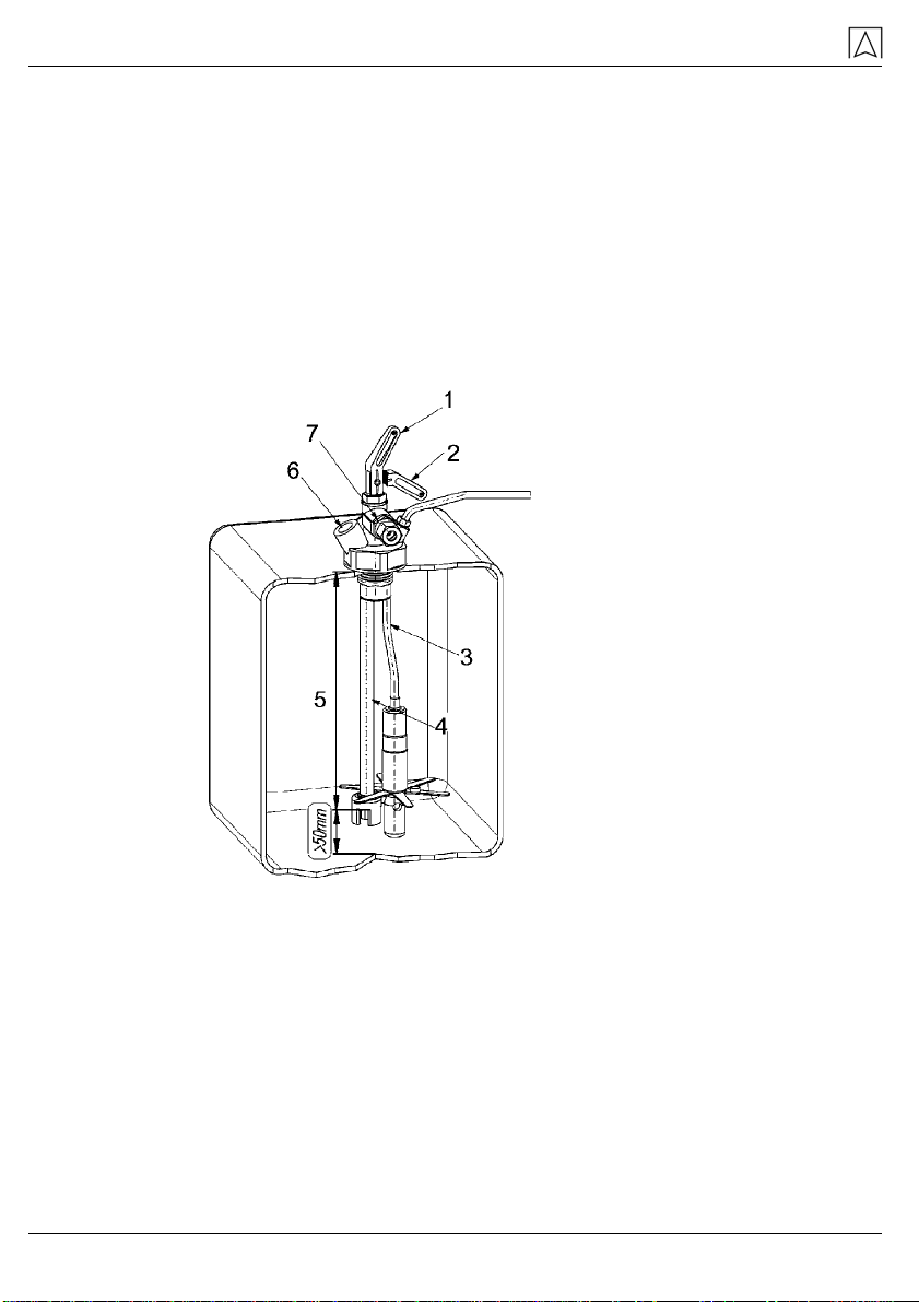
Mounting with Euroflex
1. Lower the pressure sensor into the tank.
19. Determine the required cable length as described above.
20. Tightly screw the black plastic screw (pressure screw) into the
body of the Euroflex fitting. This applies pressure to the two
O rings between the cable and the body of the Euroflex fitting,
fixates the cable and assures a pressure-tight connection.
1 Valve open
2 Valve closed
3 Measuring tube for
el. hydrostatic level
measurement
4 Suction tube
5 Tube or probe length
6 Return connection
G 3/8 IG
7 Suction connection
G 3/8 IG
Fig. 10: Mounting with Euroflex
6.8 Entering the tank data
The unit is zeroed.
The pressure sensor is installed in the tank.
Tank shape
The arrow at the bottom of the display points to the unit Litres.
The display shows the tank shape code of the currently selected
tank shape. When the unit is commissioned for the first time, the

Mounting and commissioning
DIT 01 19
display show the tank shape code 0. The 0 indicates that no
tank shape code has yet been selected.
1. Use the and keys to set the previously determined tank
shape code (see chapter 6.1, page 12).
F key to confirm the tank shape setting and continue
e of the tank facility. Press to select the digit to be
a
F key to confirm the volume setting and continue with
e bottom of the display points to the unit Per- . If
digit to be modified. Press to
ted digit in the range from 0 to 9.
cy is obtained if
21. Press the
with the tank volume data.
Tank volume
The arrow at the bottom of the display points to the unit m³.
The display shows the currently selected tank volume. If the
display shows 0000 this means that no tank volume has yet
been entered.
1. Use the and keys to set the previously determined total
volum
modified. Press to change the selected digit in the range from
0 to 9 Volumes of up to 9999 litres are entered without a comm
digit.
2. Volumes greater than 9999 litres are entered as cubic- metres
(1000 litres = 1 cubicmetre) with a comma digit. Press to
move the comma digit.
3. Press the
the tank height data.
Tank height
The arrow at th
centage. The display shows the currently selected tank height
the display shows 0000 this means that no tank height has yet
been entered.
1. Use the and keys to set the previously determined tank
height. Press to select the
change the selec
2. Press the F key to confirm the volume setting and continue with
the current filling level data.
Current filling level
The arrow at the bottom of the display points to the unit Filling
Level (FH). The display shows the filling level currently meas-
ured by the probe.
If you measure heating oil, the reading should be pretty close to the
actual filling level. If you need a greater accuracy, enter the previ-
ously determined filling level. Please note: the fuller the heating oil
tank, the greater the accuracy. The maximum accura

Operation
20 DIT 01
the tank is completely full. At levels of less than 50 %, a correction o
the value indicated is not meaningful. In order to correct the curren
filling level, you can overwrite the displayed value.
f
t
ined filling
the range from 0 to 9.
ank data are entered and the digital unit switches to
mal measuring mode.
e symbol in the top left corner of the display is no longer
7 O
7.1 Swi on the display of the digital unit. The
-
battery is not used. By pressing the F key again,
7.2 display
play points to m³.
• .
at the bottom of the display points to %.
7.3
---“. Only the current fill-
Hold down the and keys simultaneously for three seconds
to activate the "Enter tank data" mode.
1. Use the and keys to set the previously determ
level. Press to select the digit to be modified. Press to
change the selected digit in
2. Press the F key to confirm the filling level setting.
All required t
nor
Th
shown.
peration
tching on and off
Press the F key to switch
digital unit is automatically switched off approx. 2.5 minutes af
ter you press a key.
The display shows OFF.
In this mode, the
you reactivate the tank contents indicator for another 2.5 minutes
and the current filling level is displayed.
Display formats
Press the F key several times to select one of the four
formats for the filling level:
• Displaying the volume in litres.
The arrow at the bottom of the display points to litres.
• Displaying the volume in m³.
The arrow at the bottom of the dis
Displaying the volume in percent of the total contents
The arrow
• Displaying the filling level in mm.
The arrow at the bottom of the display points to FH.
Correct tank data
If the measured value exceeds the tank entered data (e.g. because
you entered incorrect tank data), the display will blink. The display
will toggle between the indicated value and “-
ing height in mm will be displayed permanently.
This manual suits for next models
1
Table of contents
Other Afriso EURO-INDEX Touch Panel manuals

Popular Touch Panel manuals by other brands

IEI Technology
IEI Technology IMK-571R Software and programming guide

Seametrics
Seametrics FT450 instructions

IEI Technology
IEI Technology IOVU-210AD-RK39 user manual

Faytech
Faytech FT32N4200W4G128GCAP manual

TCS
TCS TrainSpeed1 operating manual

Avalue Technology
Avalue Technology AID-156ST2 Quick reference guide


