2
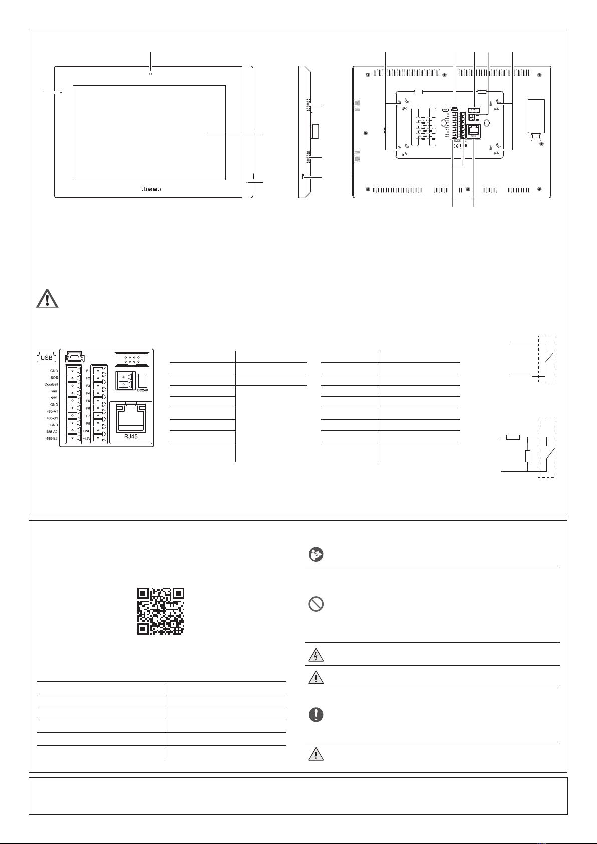
Front and rear view
2
4
1
3
5
5
6
*This device does not support standard POE power supplies, but only POE power supplies identied with 375002.
Connect the cat5/5e/6 FTP or cat5/5e/6 UTP cable with ferrite supplied to the connector.
Hereby, BTicino S.p.A., declares that the radio equipment type Indoor unit with camera 10" - 373001 / Indoor unit 10" - 373003 is in compliance with Directive 2014/53/EU.
The full text of the EU declaration of conformity is available at the following internet address: www.bticino.it/red
Read carefully before use and keep for future reference
Touching the units with wet hands is forbidden
Using liquid cleaners or aerosols is forbidden
Blocking the ventilation openings is forbidden
Modifying the devices is forbidden
Removing protective parts from the devices is forbidden
Installing the units near liquids and powders is forbidden
Installing the units near heat sources is forbidden
Installing the units near harmful gases, metal dusts or similar is forbidden
Fastening the units on unsuitable surfaces is forbidden
Danger of electrical shock
Risk of devices falling because the surface on which they are installed collapses or inappropriate installation
Switch the power supply OFF before any work on the system
Caution: Installation, conguration, starting-up and maintenance must be performed exclusively by
qualied personnel.
Check that the wall installation has been carried out correctly
Lay out the wires respecting the standards in force
Connect the power supply wires as indicated
Use only the items indicated in the technical specications for any system expansions
Remote operation may cause damage to people or property.
Warnings and consumer rightsConfiguration
The device must be congured by software. For software download, installation device documentation and for any
other information, refer to the website.
www.homesystems-legrandgroup.com
1. Microphone
2. Camera (only 373001)
3. Display 10" (touch screen)
4. Notication LED
LED ashing= notication of a message
5. Loudspeaker
6. SOS push button
7. Fixing magnets for bracket
8. USB Connector (not used)
9. Not used
10. Additional power supply clamps (not
polarized)
11. RJ45 Connector *
12. Connection clamp
All contacts must be connected to GND and the corresponding dedicated input.
The functions and wiring mode of the inputs are set by default as shown in the table and diagram, they can be customized using the software and/or straight from the device.
Tamper and Doorbell input are not customizable and SOS-GND is disable by default.
Connection clamps
SOS – GND Additional SOS call F1 – GND Infrared
DoorBell – GND Door bell call F2 – GND Magnetic contact
Tamper – GND Tamper F3 – GND Smoke sensor
GND
future use
F4 –GND Gas sensor
485-A1 F5 – GND Water sensor
485-B1 F6 – GND Magnetic contact
GND F7 – GND Magnetic contact
485-A2 F8 – GND SOS
485-B2 +12V – GND 12Vdc, maximum 150 mA
sensor power supply
560 Ω
560 Ω
GND
contacts from
F1 ÷ F8
GND
SOS
DoorBell
Tamper
Technical data
Voltage 24 Vdc
Maximum consumption 0.55 A
Max. cable section for clamps 0.8 mm²
Operating temperature (- 10) – (+ 55)°C
IP degree of protection IP30
Maximum relative humidity 93%
8 9 107 7
1112


