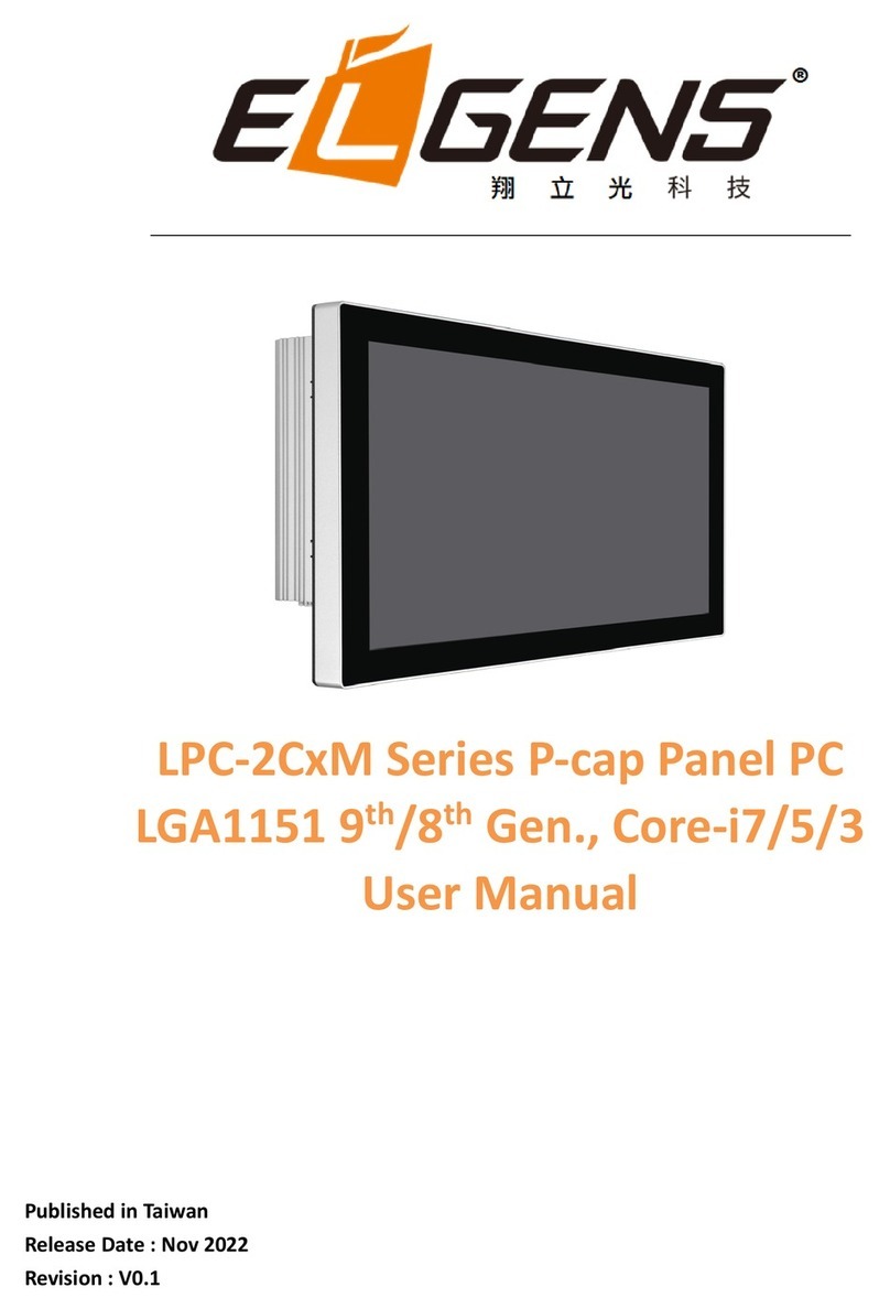
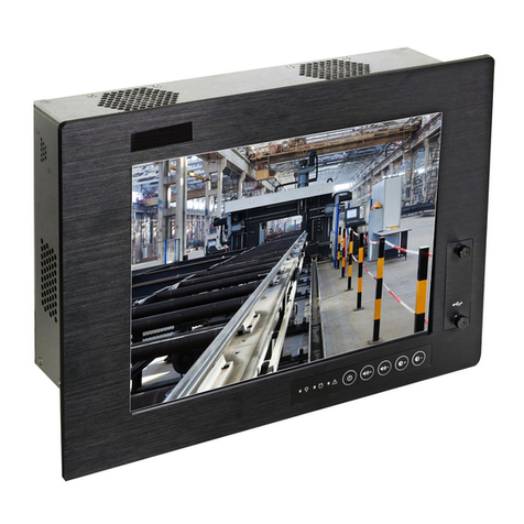
EL GENS LPC P-cap Series User manual

LPC P-cap Series User Manual
Panel PC, Intel® Braswell Celeron®3160, IP65 Compliant
Bezel & Wide Range Power Input
Published in Taiwan
Release Date : Oct 2017
Revision : V1.0
Warning!
This equipment generates, uses and can radiate radio frequency energy and if not installed and used in
accordance with the instructions manual, it may cause interference to radio communications. It has
been tested and found to comply with the limits for a Class A computing device pursuant to FCC Rules,
which are designed to provide reasonable protection against such interference when operated in a
commercial environment. Operation of this equipment in a residential area is likely to cause
interference in which case the user at his own expense will be required to take whatever measures may
be required to correct the interference.
Electric Shock Hazard –Do not operate the machine with its back cover removed. There are dangerous
high voltages inside.

ELGENS CO., LTD
LPC P-cap Series User Manual
2
Disclaimer
This information in this document is subject to change without notice. In no event shall ELGENS Co.,Ltd.
be liable for damages of any kind, whether incidental or consequential, arising from either the use or
misuse of information in this document or in any related materials.
Packing List
Accessories (as ticked) included in this package are:
□Panel Mounting Kits
□3 Pin Male Terminal Block
□Optional Adapter
□Other.___________________(please specify)
Safety Precautions
Follow the messages below to avoid your systems from damage:
◆Avoid your system from static electricity on all occasions.
◆Prevent electric shock. Don‘t touch any components of this card when the card is power-on.
Always disconnect power when the system is not in use.
◆Disconnect power when you change any hardware devices. For instance, when you connect a
jumper or install any cards, a surge of power may damage the electronic components or the
whole system.

ELGENS CO., LTD
LPC P-cap Series User Manual
3
Table of Contents
Warning!……………………………………………………………………………………………………………………….…….1
Packing List.................................................................................... ...............................2
Safety Precautions......................................................................... ...............................2
Chapter 1 Getting Started
1.1 Brief Description of LPC P-cap……………………….………….……...…..5
1.2 System Specifications……………………………………….………….……...….. 5
1.3 Dimension……………..……………………………...………………. …………...... 7
1.4 General Rear IO Replacement……….……………………….………………16
1.5 Front View…………….……………………………………….………….……...…..17
1.6 Rear View……….………………………………………….……………….……...…..18
1.7 Installation of HDD…………………….………….………………………………….19
Chapter 2 Main Board Introduction
2 . 1 M a i n b oa r d S p e c i f i ca t io n ………………………..…………….…………21
2.2 Jumpe rs Setting an d Conn ec tors……………………… ….…………… 24
Chapter 3 BIOS Setup
3.1 Entering Setup................................................................ 34
3. 2 Th e M enu Ba r. ... ... .. ... ..... ... .. .. .. .. .. .. .. . .. .... .. .. ..... .. .. .. .. .. .. .. 36
3 . 3 M a i n …. . .. . . . .. . . .. . . . . . .. . . .. . . .. . . . . . . . .. . . . . . .. . . .. . . . . . .. . . .. . . . .. . . . . .. 37
3 . 4 A d va n c e d . . . . . . . . . . . . . . . . . . . . . . . . . . . . . . . . . . . . . . . . . . . . . . . . . . . . . . . . . . . . . . . . 3 8
3 . 5 B o o t . . . . . . . . . . .. . . . . . . .. . . . . . . . . . . . . . . . . . .. . . . . . . .. . . . . . . .. . . . . . . . .. . . . . . 45
3 . 6 S e c u ri t y. . . . . . . . . . . . . . . . .. . . . . . . . . . . . . .. . . . . . . . . . . . . . . . . . . .. . . . . . . . . . . . . 50
3 . 7 C h i p s e t . . . . . . . . . . . . . . . . . . . . . . . . . . . . . . . . . . . . . . . . . . . . . . . . . . . . . . . . . . . . . . . . 51
3 . 8 P o w e r................................................................52
3 . 9 S a v e & E x i t . . . . . . . . . . . . . . . . . . . . . . . . . . . . . . . . . . . . . . . . . . . . . . . . . . . . . . . 54

ELGENS CO., LTD
LPC P-cap Series User Manual
4
Chapter 4 USB 3.0 driver installation
Chapter 5 Installation of Drivers
5.1 Windows 7 Patch Setup.…………………………...………………………… 58
5.2 Chipset Driver Setup....................…......…......………………........ 61
5.3 Audio Driver Setup….........................................................…… 63
5.4 Graphics Driver Setup……………………..……..………………….…………..……65
5.5 LAN Driver Setup...........................................................…… 67
5.6 SIO Driver Setup...........................................................…… 69
5.7 TXE Driver Setup...........................................................…… 71
5.8 USB3.0 Driver Setup...........................................................…… 73
Chapter 6 Touch Screen Driver Installation
Appendix WDT sample code

ELGENS CO., LTD
LPC P-cap Series User Manual
5
Chapter 1 Getting Started
1.1 Brief Description of LPC P-cap Series
The LPC P-cap series is a power-optimized and delivers robust performance-per-watt for
embedded HMI, powered by a Celeron® N3160 Quad Core 1.6 GHz processor. It comes with a
mSATA slot and a SATA 2.5-inch hard disk drive, up to 8GB DDR3 memory, audio jack, 2 Ethernet,
DC input, and 4 USB 3.0 ports. The unit supports Win 7 Pro/ WES7 / Win 8 / Win 10. The fanless
touch panel computer is ideal for use as Web Browser, Terminal and HMI at all levels of
automation control.
1.2 System Specifications
Model Number
LPC-P121S-01
LPC-P150S
LPC-P156W
LPC-P156W-01
Max Resolution
1024*768
1024*768
1366*768
1920*1080
Color
16.7M
16.2M
16.7M
16.2M
Luminance
350 nits
420 nits
300 nits
400 nits
View Angle
160/160
160/160
160/170
140/120
Contrast Ratio
800
800
500
500
Model Number
LPC-P170S
LPC-P173W
LPC-P185W
LPC-P190S
LPC-P215W
Max Resolution
1280*1024
1920*1080
1920*1080
1280*1040
1920*1080
Color
16.7M
16.7M
16.7M
16.7M
16.7M
Luminance
350 nits
400 nits
350 nits
350 nits
250 nits
View Angle
160/170
140/160
189/189
160/170
189/189
Contrast Ratio
1000
600
1000
1000
5000
Computing
Processor
Intel Celeron® N3160 SoC CPU
System Memory
1 x SO-DIMM, up to 8 GB DDR3L
Storage
1 x SATA3 (6.0Gb/s)
1 x mSATA (full size mini-PCIe)
External I/O Port
4 x USB 3.0
2 x GbE LAN (RTL8111G)
1 x Display Port
1 x HDMI
3 x RS-232 (COM2/3/4)
1 x RS-422/485 (COM1 default RS-485, adjustable to RS-422 by BIOS)

ELGENS CO., LTD
LPC P-cap Series User Manual
6
1 x Audio
1 x Power press button
1 x 3-Pin Power Input
Expansion Slots
None
OS support
Win 7 Pro/ WES7 / Win 8 / Win 10
Touch Screen
Type
5 Wire Res with USB Interface
Light Transmission
85%
Power Supply
Power Input
DC 9~36V Wide Range Power Input
Mechanical
Construction
Metal
IP Rating
Front Panel compliant IP65
Mounting
Panel/VESA
Environmental
Operating Temperature
0~50 ° C
Storage Temperature
-20~70 °C
Storage Humidity
10~90% @40 ゚C non-condensing
Order Information
LPC-P121S-01
12.1" P-cap Panel PC, Celeron® N3160, 1024 x 768 Reso, 350 nits LED
backlight, 4 COM, 4 USB, 2 LAN, DC 9~36V with 3-pin Power Terminal Block
LPC-P150S
15" P-cap Panel PC, Celeron® N3160, 1024 x 768 Reso, 420 nits LED
backlight, 4 COM, 4 USB, 2 LAN, DC 9~36V with 3-pin Power Terminal Block
LPC-P156W
15.6" P-cap Panel PC, Celeron® N3160, 1366 x 768 Reso, 300 nits LED
backlight, 4 COM, 4 USB, 2 LAN, DC 9~36V with 3-pin Power Terminal Block
LPC-P156W-01
15.6" P-cap Panel PC, Celeron® N3160, 1920 x 1080 Reso, 400 nits LED
backlight, 4 COM, 4 USB, 2 LAN, DC 9~36V with 3-pin Power Terminal Block
LPC-P170S
17" P-cap Panel PC, Celeron® N3160, 1024 x 768 Reso, 420 nits LED
backlight, 4 COM, 4 USB, 2 LAN, DC 9~36V with 3-pin Power Terminal Block
LPC-P173W
17.3" P-cap Panel PC, Celeron® N3160, 1920 x 1080 Reso, 400 nits LED
backlight, 4 COM, 4 USB, 2 LAN, DC 9~36V with 3-pin Power Terminal Block
LPC-P185W
18.5" P-cap Panel PC, Intel® Celeron® N3160, 1920 x 1080 Reso, 350 nits
LED backlight, 4 COM, 4 USB, 2 LAN, DC 9~36V with 3-pin Power Terminal
Block
LPC-P190S
19" P-cap Panel PC, Celeron® N3160, 1024 x 768 Reso, 420 nits LED
backlight, 4 COM, 4 USB, 2 LAN, DC 9~36V with 3-pin Power Terminal Block
LPC-P215W
21.5" P-cap Panel PC, Celeron® N3160, 1920 x 1080 Reso, 250 nits LED

ELGENS CO., LTD
LPC P-cap Series User Manual
7
backlight, 4 COM, 4 USB, 2 LAN, DC 9~36V with 3-pin Power Terminal Block
WFK-024
Wi-Fi kits w/ cable & Antenna (2.4GHz, 802.11 b/g/n, 1T1R)
WFK-524
Wi-Fi kits w/ cable & Antenna (2.4 & 5GHz, 802.11 a/b/g/n/ac + BT, 2T2R)
PB-936
Power Board for Input on board fuse / Input reverse protection / Over
current protection / Output short circuit protection
Order Information
LPC-PxxxS/W
-H / -OB / -G / -AG / -AR / -B / -V / -T
xxx = size, For example, 10.1”= 101
S = Dimension Ratio Square = 4:3 or 5:4
W= Dimension Ration Wide = 16:9 or 16:10
H = High Brightness 1000 nits LED backlight
OB = Optical Bonding
G = Glass without touch
AG = Anti-Glare
AR = Anti-Reflection
B = Power Board for
Input on board fuse
Input reverse protection
Over current
Output short circuit protection
V = Vandal Proof Glass
T = Backside Heatsink for Operating Temperature 60°C
1.3 Dimension

ELGENS CO., LTD
LPC P-cap Series User Manual
8
LPC-P121S-01 Drawing

ELGENS CO., LTD
LPC P-cap Series User Manual
9
LPC-P150S Drawing

ELGENS CO., LTD
LPC P-cap Series User Manual
10
LPC-P156W / 156W-01 Drawing

ELGENS CO., LTD
LPC P-cap Series User Manual
11
LPC-P170S Drawing

ELGENS CO., LTD
LPC P-cap Series User Manual
12
LPC-P173W Drawing

ELGENS CO., LTD
LPC P-cap Series User Manual
13
LPC-P185W Drawing

ELGENS CO., LTD
LPC P-cap Series User Manual
14
LPC-P190S Drawing

ELGENS CO., LTD
LPC P-cap Series User Manual
15
LPC-P215W Drawing

ELGENS CO., LTD
LPC P-cap Series User Manual
16
1.4 General Rear IO Placement
COM 1 is RS-485 as below pin definition, adjustable to RS-422 by BIOS
Power input terminal block pin definition is as below.

ELGENS CO., LTD
LPC P-cap Series User Manual
17
1.5 Front View of LPC- Pcap Series

ELGENS CO., LTD
LPC P-cap Series User Manual
18
1.6Rear View of LPC- Pcap Series

ELGENS CO., LTD
LPC P-cap Series User Manual
19
1.7 Installation of HDD (Below example is LPC-P185W)
1.7.1 Remove screws from below red circles.
Notice : below screws located in right and left side should be removed as well.

ELGENS CO., LTD
LPC P-cap Series User Manual
20
1.7.2 After remove the casing, we will see as below.
HDD is designed to fix with mounting bracket.
DRAM is located the bottom side of main board, as a result, we strongly suggest our client to
purchasing DRAM from ELGENS in order to save time & labor cost, and avoid the warranty issue.
This manual suits for next models
9
Table of contents
Other EL GENS Touch Panel manuals
