AGA RAYBURN Heatranger 480CD User guide

For use in GB and IE
Servicing
Instructions
Heatranger 480CD
DESN 514712
PLEASE READ THESE INSTRUCTIONS BEFORE SERVICING THIS APPLIANCE

Contents
2
SECTION CONTENTS PAGE
CONSUMER PROTECTION 3
HEALTH & SAFETY 3
SERVICING ANNUAL SERVICING 4
SERVICE SCHEDULE 4
PRE-SERVICE CHECK 5
COMBUSTION AIR 5
HOTPLATE CLEANING 5
BURNER CHAMBER/SERVICING 5
COOKER BURNER SERVICING PREPARATION 6
BURNER ACCESS 6
PARTS TO BE REMOVED TO WITHDRAW 6
COOKER BURNER
BOILER SERVICING BOILER SERVICE 7
REPLACEMENT OF PARTS REPLACEMENT OF IONSIATION PROBE 8
(ELECTRICAL CONTROLS) REPLACEMENT OF ELECTRODE 8
CONTROL BOARD REPLACEMENT 9 - 10
REPLACEMENT OF PARTS TO FIT NEW DISPLAY PANEL AND COOKER 11
(COOKER) THERMISTOR
REPLACEMENT OF PARTS REMOVAL AND REPLACEMENT OF BOILER FAN 13
(BOILER BURNER) TO FIT NEW BURNER 14
TO FIT NEW IGNITIOR, IONISATION PROBE 14
AND OVERHEAT
ELECTRODE REPLACEMENT 14
OVERHEAT STAT REMOVAL 15
REMOVAL OF HEAT EXCHANGER, ACCESS PANEL 15
AND CLEANING
EXAMINATION OF HEAT EXCHANGER TRAY 15
REPLACEMENT FLOW/RETURN SENSOR AND 16
WATER PRESSURE SWITCH
FAULT DIAGNOSTICS 17 - 18

Consumer Protection
As responsible manufacturers we take care to make sure that our products are designed and constructed to meet the
required safety standards when properly installed and used.
IMPORTANT NOTICE: PLEASE READ THE ACCOMPANYING WARRANTY
Any alteration that is not approved by Aga could invalidate the approval of the appliance, operation of the warranty and
could affect your statutory rights.
Health & Safety
This appliance may contain some of the materials that are indicated. It is the Users/Installers responsibility to ensure that
the necessary personal protective clothing is worn when handling where applicable, the pertinent parts that contain any of
the listed materials that could be interpreted as being injurious to health and safety.
Glues and Sealants
Exercise caution - if these are still in liquid form use face mask and disposable gloves.
Glass Yarn, Mineral Wool, Insulation Pads, Ceramic Fibre
Maybe harmful if inhaled. May be irritating to skin, eyes, nose and throat. When handling avoid contact with skin or eyes.
Use disposable gloves, face-masks and eye protection. After handling wash hands and other exposed parts. When
disposing of the product, reduce dust with water spray, ensure that parts are securely wrapped.
NOTE: SMOKE/SMELL EMITTED DURING INITIAL USAGE
Some parts of the cooker have been coated with a light covering of protective oil. During initial operation of the cooker,
this may cause smoke/smell to be emitted and is normal and not a fault with the appliance, it is therefore advisable to open
doors and or windows to allow for ventilation. Lift the lids to prevent staining the linings.
3

Servicing
4
It is important for the current operation of the appliance
that servicing be carried out annually by a professional or
competent person in accordance with gas safety
regulations.
With normal use, a boiler/cooker service should be carried
out immediately after the end of the heating season. The
householder should be advised to turn off both boiler and
cooker control knobs, the night preceding the day of the
service, so that the appliance will be cooled down by the
following morning, in readiness for servicing.
Before commencing any service, isolate the electricity
supply, then turn OFF the gas supply at the gas service
cocks.
WARNING: ISOLATE UNIT FROM ELECTRICITY
SUPPLY AND TURN OFF GAS AT SERVICE COCKS
BEFORE SERVICING. AFTER COMPLETING SERVICE
ALWAYS CHECK FOR GAS SOUNDNESS AND
CHECK THIS FUNCTION OF CONTROLS.
1. Carry out a pre-service check noting any operational
faults.
2. Clean the hotplate.
3. Clean the cooker burner.
4. Clean the boiler burner.
5. Clean the heat exchanger.
6. Clean and empty any debris from condensate trap.
7. Check that the flueway is unobstructed.
8. Replace all gaskets that have degraded or broken.
ANNUAL SERVICING SERVICE SCHEDULE

Operate the appliance and system, noting any faults
which may need to be corrected during service.
Check that CO2levels are within tolerance see Technical
Specification Fig. 1 in the Installation Instructions.
If these levels cannot be obtained, check gas rate and
adjust the throttle screw if required and allow readings to
stabilise. See Fig. 6.
SEE FIG. 1
Lift out the hotplate using lifting tools provided. Brush the
fins with a wire brush to remove any deposits.
SEE FIG. 2
BURNER CHAMBER
IMPORTANT: DURING CLEANING CARE MUST BE
TAKEN NOT TO DAMAGE THE CERAMIC FIBRE
INSULATION INSIDE THE COMBUSTION CHAMBER.
1. Lift insulation covers and remove hotplate using lifting
hooks provided.
2. Clean the flueway by inserting the flexible brush
through top plate aperture, directing it towards the flue
outlet. Scrape the deposits towards the burner
chamber.
3. Thoroughly clean burner chamber flueway.
4. Carefully vacuum any debris that has fallen down into
the burner chamber.
5. Replace the hotplate ensuring the underside ribs lie
over the oven, and that it seals to the top plate.
Servicing
PRE-SERVICE CHECK
5
HOTPLATE CLEANING
FIG. 1 DESN 510145 A
COOKER BURNER
CHAMBER/SERVICING
FIG. 2 DESN 514992J
COMBUSTION AIR

WARNING: BEFORE REMOVING SERVICE ACCESS
COVERS OR THE BURNERS ENSURE THAT ALL
ELECTRICAL SUPPLIES TO THE APPLIANCE HAVE
BEEN ISOLATED.
SEE FIG. 3
1. Open up the bottom door access door. Remove door
and put in a safe place.
2. Remove the 4 inner panel securing screws and
remove panel.
3. Remove the 3 plinth securing screws and remove
plinth.
1. Ensure cooker gas cock is closed.
2. Disconnect flexible gas inlet as shown, ensuring not to
lose o-ring. (See Fig. 4).
3. All of the items in Fig. 5 need to be disconnected
before the burner assembly can be removed.
Cooker Burner Servicing
PREPARATION
6
BURNER ACCESS
FIG. 3 DESN 514878
FIG. 4 DESN 514879
PARTS TO BE REMOVED TO
WITHDRAW COOKER BURNER
DESN 514880FIG. 5
FIG. 6 DESN 514881

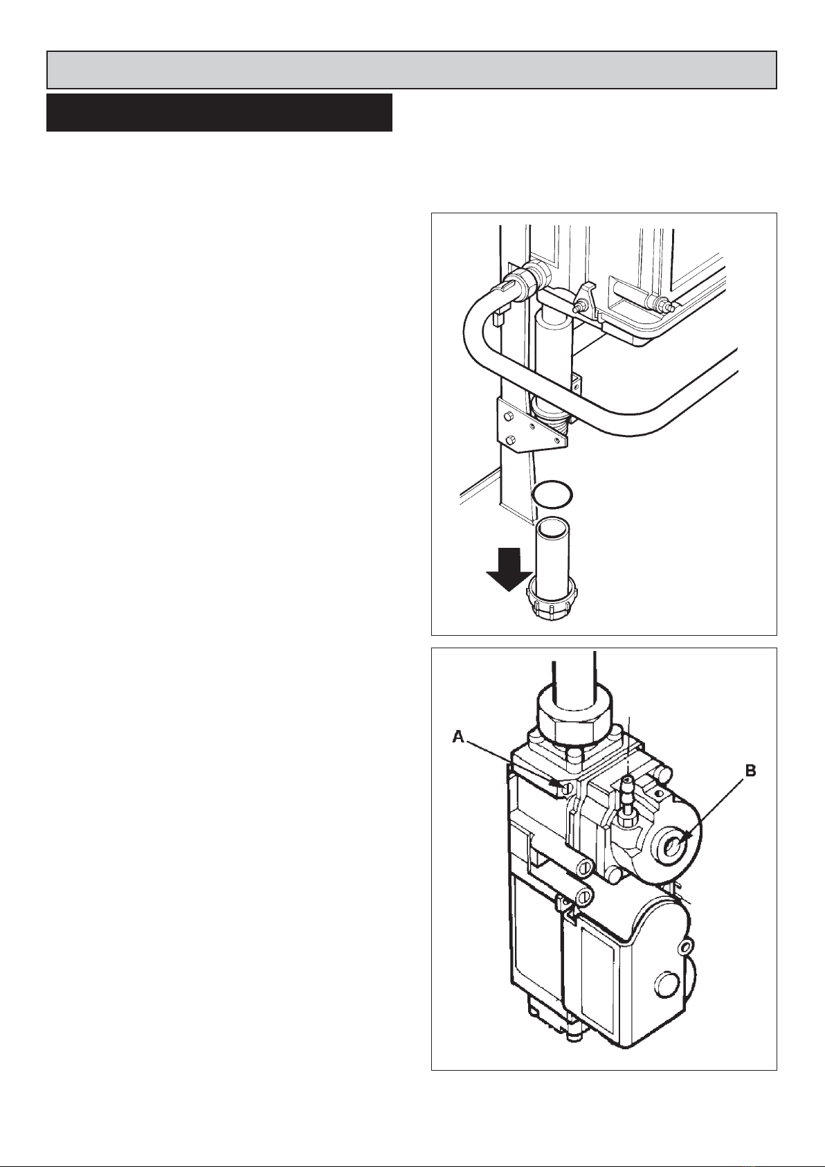
CONDENSATE TRAP SERVICE
Unscrew condensate trap base and check for excessive
deposits. If levels are acceptable wash out any deposits
and replace. (See Fig. 7)
COMBUSTION ANALYSIS
Check that the CO2/CO levels are within tolerances shown
in Fig. 1.
To check the levels at full rate, turn the boiler knob fully
clockwise.
To check the levels at the low rate, turn the boiler knob to
the first segment on the dial.
If these levels are within the tolerance, no further action is
required with the boiler.
If levels are not within tolerance check for possible causes
e.g. blocked flue, faulty fan etc. If no other fault can be
detected, the gas valve needs to be adjusted manually.
To do this, turn the boiler knob fully clockwise to create the
highest possible demand.
Check that CO2/CO levels are within stated levels (See
Fig. 1). If the valve are found to be inconsistent with these,
turn the gas valve regulator A (See Fig. 8) in the
appropriate direction. Turning clockwise will decrease the
CO2; turning anti-clockwise will increase the CO2. Please
note that due to the sensitivity of the screw, only small
adjustments will be necessary.
Once adjustment has been made, wait until CO2level
stabilises and recheck the combustion. Repeat the above
steps as necessary.
Check that CO2levels are within stated levels at minimum
rate, turn knob to first segment on the display.
Using the method detailed above, run the boiler at its
minimum output. Wait for the boiler to stabilise and
perform the combustion analysis, check the results
against those in the Technical Specification Fig. 1. in the
Installation Instructions.
If the valves are found to be inconsistent with these, turn
the gas valve regulator B (See Fig. 8) in the appropriate
direction. Turning clockwise will increase the CO2; turning
anti-clockwise will decrease the CO2. Please note that due
to the sensitivity of the screw, only small adjustments will
be necessary (1/8 of a turn).
NOTE: Unscrew cap and adjust accordingly.
Once adjustment has been made, wait until the CO2level
stabilises and recheck the combustion. Repeat the above
steps as necessary.
After completion of calibration, recheck the CO2at
maximum output. It is also advisable to check the gas
capacity at the metre against the figures given in the
technical specification in Fig. 1.
Boiler Servicing
BOILER SERVICE
FIG. 7 DESN 515015
FIG. 8 DESN 515016
7

SEE FIG. 8
1. Turn off power to the appliance.
2. Unscrew the fixing screw and withdraw probe.
3. Replace probe, ensuring both the gasket and spark
return are also fitted.
SEE FIG. 9
1. Turn off power to the appliance.
2. Unscrew the fixing screw and withdraw probe.
3. Unclip the electrode plug, by simply pulling away
4. Replace electrode and gasket and screw in tightly.
Replacement of Parts (Electrical Controls)
REPLACEMENT OF IONISATION
PROBE
8
REPLACEMENT OF ELECTRODE
FIG. 8 DESN 514882
FIG. 9 DESN 514883

SEE FIGS. 10 & 11
1. Remove plinth.
2. Unscrew 2 bolts fixing the board to the base.
3. Move the terminal strip and bracket to allow removal of
the main PCB.
4. The extra lengths on the wires should allow the PCB to
be withdrawn to the front of the appliance.
5. All of the connections can then be disconnected.
6. To replace the PCB, unscrew the 4 bolts and then
simply fit a new control board.
Replacement of Parts (Electrical Controls)
CONTROL BOARD REPLACEMENT
FIG. 10 DESN 514885
FIG. 11 DESN 514886
9

Replacement of Parts (Electrical Controls)
10
FIG. 12 DESN 514884

Replacement of Parts (Cooker)
11
SEE FIG. 13 & 14
1. Remove glass front facia by unscrewing buttons and
removing 2 M5 screws.
2. Pull off control knobs and remove glass.
3. Undo 4 screws on the chassis and remove from front
plate ensuring electrical connector is disconnected.
4. Disconnect required thermsistor from main board.
5. Remove thermistor from the tie wrap clamp.
6. Unscrew required thermocouple using a spanner. (See
Fig. 14)
7. Replace with new thermocouple and re-connect.
8. Replace all parts in reverse order.
TO FIT NEW DISPLAY PANEL &
COOKER THERMISTOR
FIG. 13 DESN 514887
FIG. 14 DESN 514888

Replacement of Parts (Boiler Burner)
12
FIG. 15 DESN 514889

1. Close boiler gas cock.
2. Unscrew boiler gas inlet. (See Fig. 17).
3. Remove 3 M6 nuts from boiler manifold. (See Fig. 17)
4. Unscrew boiler gas valve connections and remove gas
train. (See Fig. 16).
5. Disconnect air inlet duct by unscrewing hose clip (See
Fig. 18).
6. Disconnect electrical connection at the back of the fan.
(See Fig. 18).
7. Remove air pressure tube from gas valve (See Fig.
16).
8. The manifold and fan can now be pulled out and
removed through the lower service door entry.
9. To separate the fan from the manifold, unscrew the 2 x
M5 cap head screws with an appropriate allen key.
(See Fig. 18).
10.The fan and manifold can now be separated.
11.The air inlet manifold is removed by unscrewing the 3
x M4 screws. (See Fig. 19).
Replacement of Parts (Boiler Burner)
13
REMOVAL AND REPLACEMENT OF
BOILER FAN
FIG. 16 DESN 514890
FIG. 17 DESN 514891
FIG. 18 DESN 514892
FIG. 19 DESN 514893

SEE FIG. 20
1. Remove manifold and fan as shown previously.
2. The burner can now be simply pulled out.
SEE FIG. 21
1. Remove the 5mm cap screw and pull out the probe.
2. Disconnect the wire from the service block.
3. Withdraw the probe and replace.
SEE FIG. 22
1. Disconnect the HT plug.
2. Unscrew 2 x M5 cap screws.
3. Remove electrode from heat exchanger.
Replacement of Parts (Boiler Burner)
14
TO FIT NEW BURNER
FIG. 20 DESN 514894
FIG. 21 DESN 514895
TO FIT NEW IGNITOR, IONISATION
PROBE AND OVERHEAT
ELECTRODE REPLACEMENT
FIG. 22 DESN 514897

SEE FIG. 23
1. Disconnect 2 flag connectors from the stat.
2. Unscrew overheat and remove.
SEE FIG. 24
1. Unscrew 4 x M6 nuts.
2. Brush and deposits away with a suitable brush.
Remove 6mm nut (23) the tray should now drop at the
front. DO NOT remove the tray, simply check that the tray
is clean and not full of deposits. If the tray is deposit-free,
lift tray back into position and re-fit the nut to clamp the
tray in position.
Replacement of Parts (Boiler Burner)
15
OVERHEAT STAT REMOVAL
FIG. 23 DESN 514898
FIG. 24 DESN 514899
REMOVAL OF HEAT EXCHANGER
ACCESS PANEL AND CLEANING
EXAMINATION OF HEAT
EXCHANGER TRAY

SEE FIG. 25 & 26
1. To replace the flow and return sensor disconnect the
electrical connection and then unclip from the pipe.
(See Fig. 25).
2. To replace the water pressure switch, the system must
first be drained.
3. Disconnect 2 electrical connectors before unscrewing
the switch.
Replacement of Parts (Boiler Burner)
REPLACEMENT FLOW/RETURN
SENSOR & WATER PRESSURE SWITCH
FIG. 25 DESN 514900
16
FIG. 26 DESN 514901

17
Fault Diagnostics
Code Error
No ignition on cooker
burner after 3 attempts
A1
Possible Cause
a. Ignition wire/plug has become detached or is broken.
b. No current is being received from ionisation probe.
c. Gas valve is not allowing any gas to the burner/throttle is
not correctly set.
d. Air proving rubber tube (from valve to air inlet tubing has
become detached or is ripped).
e. Burner fan is not operating correctly.
f. Blocked flue and/or air inlet.
Correction
a. Check both wiring and plug for faults.
b. Remove link wire from ionisation block and check for μA
reading during ignition.
c. Check electrical connector is fitted to the valve and the
solenoid open during ignition.
d. Check rubber tube is connected properly and there are no
tears.
e. Ensure connections to fan are made and it is running
during ignition attempts.
f. Inspect flue/air inlet for any blockages throughout the
system.
A2 No ignition on boiler burner
after 3 attempts
a. Ignition wire/plug has become detached or is broken.
b. No current is being received from ionisation probe.
c. Blocked condensate trap/pipe earthing ionisation probe.
d. Gas valve is not allowing any gas to the burner/throttle is
not correctly set.
e. Air proving rubber tube (from valve to fan has become
detached or is ripped).
f. Blocked flue and/or air inlet.
a. Check both wire and plug for faults.
b. Remove link wire from ionisation block and check for μA
reading during ignition.
c. Unscrew condensate trap base, only a small amount of
water should escape otherwise a blockage is likely.
d. Check electrical connector is fitted to the valve and the
solenoid opens during ignition.
e. Check rubber tube is connected properly and there are no
tears.
f. Inspect flue/air inlet for any blockages throughout the
system.
A3 Boiler Overheat Error/
Pressure Sensor Error
a. Heating system below required pressure (1 bar) or above
required pressure (3 bar).
b. Pressure stat not wired correctly/faulty stat.
c. Overheat thermocouple triggered on heat exchanger
body. (Usually caused by air lock after refilling or by faulty
pump).
a. Heating system not pressurised correctly/open system
being used.
b. Check wiring/wire out stat to determine whether faulty.
c. Ensure pump is running and all air is removed from
system/wire out stat to determine whether faulty.
A4 Overheat on cooker a. Oven temperature found to be >270°C a. Check cooker flue for blockage/replace cooker
thermistors.
A5 Differential between the 2
cooker thermistors >20°C
for longer than 10 minutes
a. Sensors not fitted correctly/faulty. a. Ensure thermistors are fitted correctly/replace sensors.
A6 Boiler fan error a. Wiring connector not fitted correctly/faulty fan. a. Check connections/replace fan.
A8 Appliance control board
settings incorrect
a. Incorrectly installed software in manufacture a. Reprogram control board with correct software/replace
PCB.
Cooker fault code is shown on R.H. side of screen Boiler fault code is shown on L.H. side of screen

18
Fault Diagnostics
Code Error
Shorted/Open flow sensorE1
Possible Cause
a. Connection fault/faulty thermocouple.
Correction
a. Check wiring connection/replace stat.
E2 Cooker thermistor T1
Open/Shorted
a. Connection fault/faulty thermistor. a. Check wiring connection/replace stat.
E3 Cooker thermistor T2
Open/Shorted
a. Connection fault/faulty thermistor. a. Check wiring connection/replace stat.
E4 Mains error a. Live and Neutral incorrectly fitted.
b. Bad earth connection.
c. Incorrect mains frequency.
a. Check wiring.
b. Check wiring.
c. Check supply frequency.
E5 Boiler unexpected flame
detected
a. Possible wiring error.
b. Possible gas leak.
a. Check all electrical connections.
b. Check all gas connections.
E6 Cooker unexpected flame
detected
a. Possible wiring error.
b. Possible gas leak
a. Check all electrical connections.
b. Check all gas connections.
E9 Internal board error a. Manufacturing fault. a. Check wiring/replace board.
A9 Internal Board Error a. Wiring incorrectly installed on site.
b. PCB manufacturing unit.
a. Check wiring loom/replace PCB

19

20
Table of contents
Other AGA Cooker manuals

AGA
AGA Elise AEL48IN-SS User manual

AGA
AGA Falcon Mercury 1200 Induction Instruction Manual

AGA
AGA Six Four Series User manual

AGA
AGA CITY60 CONTEMPORARY User manual

AGA
AGA eR7 Series User manual

AGA
AGA 7 Series Instruction Manual

AGA
AGA GC User manual

AGA
AGA G.C. P.V. User manual

AGA
AGA C User manual

AGA
AGA R3 100-4i Instruction Manual