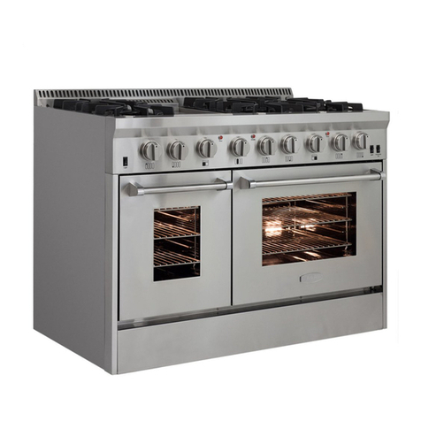
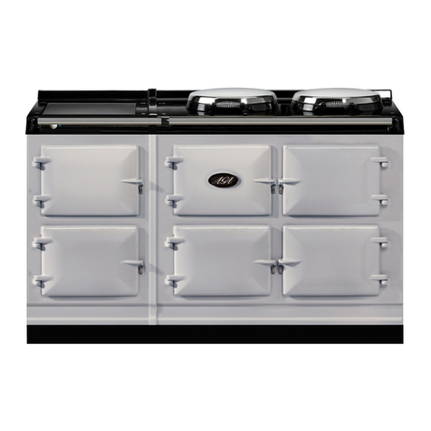
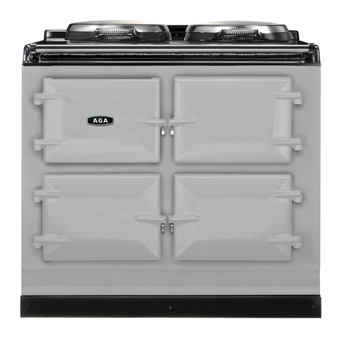
AGA SIX-FOUR SERIES - DC6 User manual

AGA SIX-FOUR SERIES - DC6 (FFD)
OWNERS MANUAL
05/13 EINS 514241
PLEASE READ THESE INSTRUCTIONS BEFORE USING THIS APPLIANCE
INSTALLER: LEAVE THESE INSTRUCTIONS WITH THE APPLIANCE
CUSTOMER: KEEP THESE INSTRUCTIONS FOR FUTURE REFERENCE
Comprising
Servicing, Installation & Users
Instructions
&
Cooking Guide
For use in Australia
DESN 512387

SECTION PAGE
INSTALLATION SECTION 3
INSTALLATION 4
TECHNICAL DATA 5
FITTING AND PRODUCT DIMENSIONS 6
ELECTRICAL CONNECTION 7
CONNECTING TO GAS 8
COOKER STABILITY 9 - 10
PRESSURE TESTING 10
LEVELLING AND MOBILITY WHEELS 11
FITTING OF HOTPLATE CASTINGS AND PAN 12 - 16
SUPPORTS
SPLASHBACK 16
USERS GUIDE 17
GENERAL INFORMATION 18
SAFETY PRECAUTIONS AND HINTS 19
PRODUCT VIEW 20
CONTROL PANEL 21
GAS HOTPLATE 22 - 23
TO FIT PAN SUPPORTS 24
GRIDDLE PLATE 25
SETTING UP THE COOKER FOR USE 26
SIMMERING OVEN 27
SIMMERING OVEN RECIPES 28 - 31
THE GRILL 32
THE OVENS 33
OVEN COOKING GUIDE 34 - 38
THE MINUTE TIMER 39
AUTOMATIC COOKING CONTROL 40 - 41
CLEANING AND CARING FOR YOUR COOKER 42 - 47
SERVICING SECTION 48
SERVICING 49 - 58
WIRING DIAGRAM 59
2
CONTENTS

Installation
Section
3
CAUTION: THIS UNIT IS HEAVY, PROPER EQUIPMENT AND ADEQUATE MAN
POWER MUST BE USED IN MOVING THIS RANGE TO AVOID DAMAGE TO THE UNIT
OR THE FLOOR.
Remember, when replacing a part on this appliance, use only spare parts that you can be
assured conform to the safety and performance specification that we require. Do not use
reconditioned or copy parts that have not been clearly authorised by AGA.

INSTALLATION
PLEASE READ THESE INSTRUCTIONS BEFORE INSTALLING OR USING THIS
APPLIANCE.
THIS APPLIANCE SHALL BE INSTALLED BY AUTHORISED PERSONS AND IN
ACCORDANCE WITH THE MANUFACTURER’S INSTALLATION INSTRUCTIONS, LOCAL
GAS FITTING REGULATIONS, MUNICIPAL CODES, ELECTRICAL WIRING REGULATIONS,
AS5601/AG601 - GAS INSTALLATIONS AND ANY OTHER STATUTORY REGULATIONS.
PRIOR TO INSTALLATION, ENSURE THAT THE LOCAL DISTRIBUTION CONDITIONS
(NATURE OF GAS AND GAS PRESSURE) AND THE ADJUSTMENTS OF THE APPLIANCE
ARE COMPATIBLE.
THE GAS ADJUSTMENT CONDITIONS FOR THIS APPLIANCE ARE STATED ON THE DATA
PLATE WHICH IS SITUATED IN THE RIGHT HAND VENT SLOT AT THE BASE OF THE
APPLIANCE.
The appliance wiring diagram is situated on the back panel.
The appliance is not connected to a combustion products evacuation device. It shall be installed
and connected in accordance with current installation regulations. Particular attention shall be
given to the relevant requirements regarding ventilation.
It should be in accordance also with any relevant requirements of the Gas Region and Local
Authority.
On completion test the gas installation for soundness and purge. Leak testing of the appliance
shall be conducted according to the manufacturers instructions.
NOTE: Use soapy water on new gas connections to ensure there are no gas leaks.
WARNING - ELECTRIC SHOCK HAZARD
It is the customers responsibility to contact a qualified installer to make sure the electrical
installation is adequate and in conformance with SAA ELECTRICAL WIRING RULES AS 3000.
Take special care when cutting hole in walls or floors. Electrical wires may be behind the wall or
floor covering and could cause an electrical shock if you touch them.
Locate any electrical circuits that could be affected by the installation of this product and
disconnect power circuit.
Electrical earth is required on this appliance.
Do not use an extension lead with this appliance.
Check with a qualified electrician if you are not sure the appliance is earthed properly.
Failure to follow these instructions could result in death or serious injury.
The appliance is designed for the voltage stated on the data plate.
The AGA Six-Four Series - DC6 is supplied from the manufacturers in a fully tested condition.
Check the operation of the appliance to ensure the hotplate burners ignition operates correctly
or individual burners and in combination with other burners. Check flame picture and flame
stability.
Check oven elements heat up and that ovens reach temperature.
4

HOTPLATE
NATURAL GAS
L.H.F. R.H.F. R.H.R. L.H.R. CENTRE CENTRE
WOK FRONT REAR
BURNER TYPE ULTRA-RAPID RAPID RAPID SEMI-RAPID SEMI-RAPID ULTRA-RAPID
MAXIMUM HEAT 4.2 kW 3.3 kW 3.3 kW 1.95 kW 1.95 kW 4.2 kW
INPUT 15 MJ/hr
12 MJ/hr
12 MJ/hr 7.0 MJ/hr 7.0 MJ/hr 15 MJ/hr
INJECTOR MARKING
MAIN 72X 155 155 118 118 180
SECONDARY 2 x 112 - - - - -
PRESSURE POINT POSITION: REAR RH SIDE OF HOTPLATE
PRESSURE SETTING: 1kPa (4” w.g.)
BURNER IGNITION: H.T. SPARK
PROPANE
L.H.F. R.H.F. R.H.R. L.H.R. CENTRE CENTRE
WOK FRONT REAR
BURNER TYPE ULTRA-RAPID RAPID RAPID SEMI-RAPID SEMI-RAPID ULTRA-RAPID
MAXIMUM HEAT 4.2 kW 2.7 kW 2.7 kW 1.75 kW 1.75 kW 4.2 kW
INPUT 15 MJ/hr
9.6 MJ/hr
9.6 MJ/hr 6.3 MJ/hr 6.3 MJ/hr 15 MJ/hr
(300 g/h) (190 g/h) (190 g/h) (125 g/h) (125 g/h) (300 g/h)
(0.59 l/h) (0.37 l/h) (0.37 l/h) (0.246 l/h) (0.246 l/h) (0.59 l/h)
INJECTOR MARKING
MAIN 46 85 85 65 65 105
SECONDARY 2 x 66 - - - - -
PRESSURE POINT POSITION: REAR RH SIDE OF HOTPLATE
PRESSURE SETTING: 2.75 kPa (11” w.g.)
BURNER IGNITION: H.T. SPARK
ELECTRIC GRILL AND OVENS WEIGHT OF APPLIANCE: 220 kg
TOP OVEN POWER RATING - 2.2 kW
GRILL ELEMENT - POWER RATING 2.45 kW
SLOW COOKING OVEN - POWER RATING 1.0 kW
LOWER OVEN (FAN) - 2.2 kW
240 VOLT 50 Hz SINGLE PHASE 30 AMP
The data plaque is located on a pull out plate - lower front of appliance (See Fig. 10, Page 20).
TECHNICAL DATA
5

FITTING AND PRODUCT DIMENSIONS
6
Fig. 1 DESN 512388 C
Any side wall above the cooker on either side shall be not less than 60mm horizontally from the
cooker (Fig. 1).
Surfaces over the top of the cooker must not be closer than 650mm.
A minimum clearance of 1000mm must be available at the front of the cooker to enable it to be
serviced.
The vent slots in the back of the top plate must not be obstructed.
The cooker must stand on a firm and level surface. We recommend that any soft material such
as linoleum is removed.
PLEASE NOTE WHEN FITTING A COOKER HOOD
If a cooker hood is to be fitted, we only recommend the 6-4 Series CH900 cooker hood. It must
be installed at a height of at least 800mm above the hotplate.

Electrical earthing is required on this range.
Disconnect the power to the junction box before making the electrical connection.
This range must be connected to an earthed, metallic, permanent supply or a earthing
connector should be connected to the earth terminal or wire lead on the range.
Do Not earth to gas pipe. Failure to follow these instructions could result in death or
serious injury.
A three-wire single phase 240-volt, 50-Hz, AC-only electrical supply is required on a separate,
30-amperes circuit, fitted with a double-pole isolator.
ELECTRICAL CONNECTION IS LOCATED AT THE TOP RIGHT HAND SIDE OF THE
APPLIANCE, BEHIND SIDE PANEL. DURING INSTALLATION REMOVE THE RIGHT HAND
SIDE PANEL TO CONNECT ELECTRICAL SUPPLY.
Remove 3 screws securing side panel to gain access to mains terminal. See Fig. 3 for location
of cover.
Remember that the mains electrical cable must be routed through the grommet at the rear right
hand side of the cooker, near the top, before connecting to the mains terminal connection.
REFER TO FIG. 2 for wire connection to appliance.
Remember that an excess of cable length is required inside the cooker to allow for possible
servicing of the spark generator.
Remember that an excess of cable length is required behind the cooker for the withdrawal of the
cooker from between the kitchen units etc.
The cooker requires a 30 amp power supply and must be connected to the mains with a cable
which complies with SAA Wiring Rules AS 3000.
Remember that an excess of cable length is required for the possible withdrawal of the range.
ALWAYS DOUBLE CHECK CONNECTIONS AND ENSURE TERMINALS ARE FULLY
TIGHTENED.
THE ISOLATOR MUST NOT BE POSITIONED IMMEDIATELY ABOVE THE COOKER, BUT
MUST BE SITED WITHIN 2 METRES OF THE APPLIANCE.
Replace the right hand side panel once electrical connection has been made and replace fixing
screws.
NOTE: Ensure that the insulation card covering the mains terminal is in place, between the side
7
ELECTRICAL CONNECTION
Fig. 2 DESN 513312

This appliance can be connected with rigid piping as specified in AS5601 table 3.1 or with a
flexible hose which complies with AS/NZS1869, class B or D and in accordance with AS5601 for
a high level connector.
To allow ease of servicing and cooker mobility, an approved flexible 4ft hose should be fitted .
Supply piping should not be less than R 1/2 (1/2” BSP). Connection is made to the R 1/2 (1/2”
BSP) female threaded entry in the inlet block located just below the hotplate level on the rear
right hand side of the cooker.
The gas connector must be fitted to the wall in the shaded area dimensioned in Fig. 4. Take into
account that it must be possible to pull the cooker forward sufficiently for servicing. Ensure
flexible hose is not trapped between cooker back panel and rear wall. Ensure hose is routed
within the shaded area and away from the shielded oven vent. The flexible hose must be in
accordance with the relevant standards.
IMPORTANT: THE GAS SUPPLY CONNECTION AT THE WALL MUST NOT PROJECT OUT
FROM THE WALL BY MORE THAN 45mm, SO THAT IT DOES NOT FOUL WITH THE BACK
OF THE COOKER.
Check for gas soundness after connecting the appliance.
8
CONNECTING TO GAS
Fig. 3 DESN 513190

Fig. 3B
CENTRE LINE OF
COOKER
BRACKET
FLOOR
WALL
A stability bracket shall be secured firmly to the fabric of the building. For positioning of bracket
(See Fig. 3). A safety chain should also be anchored firmly to the wall and cooker to prevent
strain on the gas connection, when the cooker is withdrawn for servicing. When fitting a
stability bracket and chain refer to Fig. 3, 3A and 3B.
Fig. 3A DESN 513188
9
COOKER STABILITY
The cooker must have an anti-tip bracket correctly installed as per these instructions. If you pull
the appliance out from the wall for any reason, make sure that the device is properly engaged
when you push the cooker back against the wall. If it is not, there is a possible risk of the cooker
tipping over and causing injury if you or a child stand, sit or lean on an open door.
If disconnection of the restraining chain is necessary then ensure restraining chain is reattached
as appliance us relocated in its original position.
To reduce the risk of tipping, the range must be secured by a properly installed anti-tip bracket
supplied the appliance. The bracket must be fitted within the shaded area shown in the diagram
using 2 x screws (No. 10 x 1 1/4) fixed in the wall or floor, longer screws may be required
depending on the wall or floor covering.

The pressure test point is situated at the rear right hand side of the hotplate.
Place the wok burner head, burner cap and ring into position on the hotplate. Light the burner
by pushing in the appropriate control knob, and turning it anti-clockwise to the full on position.
For Natural Gas appliance, manifold pressure is 1kPa (4” w.g.)
For LPG appliance (propane only), manifold pressure is 2.75 kPa (11” w.g.).
Turn off the taps, disconnect the pressure gauge and refit burner head.
The gas regulator is attached to the rear panel at the rear left hand side of the appliance, just
below hotplate level.
10
PRESSURE TESTING
POSITION OF GAS BAYONET ON WALL (locate in shaded areas)
IMPORTANT: THE GAS SUPPLY CONNECTION AT THE WALL MUST NOT PROJECT
OUT FROM THE WALL BY MORE THAN 45MM, SO THAT IT DOES NOT FOUL WITH THE
BACK OF THE COOKER.
Fig. 3B DESN 512390

INSTALLATION AND LEVELLING
The DC6 is designed to stand on a flat and level surface, however any unevenness may be
overcome by adjusting the four levelling feet at each corner of the base plate. The adjusting
screws are accessed by removing left and right hand hotplate castings (See section ‘To Remove
Hotplate Castings - Servicing Section Page 50). To raise the cooker turn screw clockwise, to
lower turn screw anti-clockwise.
There are rollers on the base of the cooker to allow for positioning.
When the cooker is in the correct position the four levelling feet can be adjusted to level the
cooker. The feet must be lowered enough to prevent the cooker rolling out of position. (See Fig.
5).
11
DESN 512391 BFig. 5
LEVELLING AND MOBILITY WHEELS

HOTPLATE CASTINGS
1. Attach earth cable from centre of casting to cooker chassis and locate over burner bodies.
Repeat for LH and RH castings and that the gaskets are fitted where the outer castings
overlap centre castings. Ensure that earth cables are attached. (See Fig. 6A).
2. Secure castings using 8 profiled fixing nuts. DO NOT OVERTIGHTEN. (See Fig. 6B).
FITTING OF HOTPLATE CASTING AND PAN SUPPORTS
12
Fig. 6B
Fig. 6A
DESN 512393 C
DESN 512400 A

4. Position burner caps onto burner bodies. (See Figs. 7A, 7B, & 7C).
13
Fig. 6C DESN 512419 A
3. Fit and secure six burner rings using M4 screws on rear left hand, front centre, front right
hand and rear right hand burners. Use No. 6 3/8 screw on front left hand and centre rear
burners. (See Fig. 6C).
NOTE: The fitting of the LH and centre burners are the same as shown in Fig. 6B.
Fig. 7A DESN 513714
ULTRA RAPID BURNER
DESN 513512
WOK BURNER

Fig. 7C DESN 511617
FITTING BURNER CAP - RAPID AND SEMI-RAPID BURNERS
BURNER CAP
RETAINING LUGS
14
Fig. 7B DESN 511618
BURNER CAP
ASSEMBLY OF RAPID AND SEMI-RAPID BURNERS
BURNER HEAD
ELECTRODE

5. Fit the pan supports in the following order. The pan supports are marked on the underside to
correspond to the markings below. The pan supports must locate in the recesses in the
hotplate casting. (See Fig. 8A and 8B).
15
IMPORTANT
It is VERY for the performance and reliability of the hob that the pan supports are fitted in
accordance with the AGA-SIX FOUR SERIES - DC6 OWNERS MANUAL.
To help identify the correct location of the pan supports, the centre rear pan support has been
uniquely designed with a tag as shown. This pan support must be fitted in the rear centre position
with the tag pointing towards the back of the appliance.
Fig. 8A
Fig. 8B DESN 512995 A

1. Locate tabs on rear of splashback assembly, into the bracket on the upper rear of the cooker.
(See Fig. 9).
Push fully into place.
Fig. 9 DESN 512394
16
SPLASHBACK
Fig. 8C DESN 513716
TO ADJUST PAN SUPPORT LEVEL
1. Loosen retaining nut using 8mm spanner (See Fig. 8C).
2. To prevent rocking adjust the pan support using 2.5mm allen key.
3. Check pan support is level with opposing pan supports.
4. Retighten retaining nut.
HANDRAIL FITTING
1. Position handrail assembly onto locating studs at each end of facia. Ensure the grub screw
at each end of the hand rail is facing downwards.
2. Push handrail assembly fully against facia and lock in place by tightening 2 grub screws (2
1/2mm). (See Fig. 6A).

Users
Guide
17

18
GENERAL INFORMATION
As responsible manufacturers we take care to make sure that our products are designed and
constructed to meet the required safety standards when properly installed and used.
IMPORTANT NOTICE Any alteration that is not approved by Aga could invalidate the approval
of the appliance, operation of the warranty and could affect your statutory rights.
In the interests of safety and effective use, please read the following instructions before using
your new Aga appliance.
The use of gas on a cooking appliance results in the production of heat and moisture in the room
in which it is installed. Ensure that the kitchen is well ventilated, keep the natural ventilation holes
open or install a mechanical ventilation device (mechanical extractor hood).
Prolonged intensive use of the appliance may call for additional and/or more effective ventilation,
for example, opening of a window, or, increasing the level of mechanical ventilation where
present.
Installation must be to local and national wiring regulations and carried out by a qualified
engineer, from an authorised distributor.
A little smoke and some odour may be emitted when first switched on. This is normal and
harmless (from oven lagging and starch binder on the element insulation) and will cease after a
short period of use.
Your appliance has a gas hob, three electric ovens; the lower right hand oven is a slow cooking
oven, the upper right hand oven is a conventional oven.
The lower left hand oven is an electric fan oven. The fan behind the rear panel ensures an even
distribution of heat within the oven during cooking, ie. the temperature at the lowest shelf position
is the same as the temperature at the highest shelf position.
The electric grill is situated in the roof of the top left hand compartment.
Refer to the diagram (See Fig. 10) to familiarise yourself with the cooker and refer to the relevant
section for the simmering oven, fan oven, conventional oven, grill and gas hotplate etc.
Your cooker is supplied with the following accessories:
5 oven shelves
1 large roasting tin
1 grill shelf
1 grill pan
1 grill pan grid
1 baking tray
1 griddle plate
The following loose parts are also packed with:
6 pan supports (cast)
3 spillage wells (cast)
6 burner caps
6 burner heads
2 burner rings
1 handrail assembly
1 splashback assembly
1 fitting kit
6 burner skirts
2 spacer rings
2 beauty rings
6 gaskets

1. DO NOT USE THE APPLIANCE AS A SPACE HEATER.
2. DO NOT SPRAY AEROSOLS IN THE VICINITY OF THIS APPLIANCE WHILE IT IS IN
OPERATION.
3. Do not stand obstacles against any part of the range cooker.
4. This appliance is not intended for use by young children or infirm persons without
supervision.
5. Young children should be supervised to ensure they do not play with the appliance.
6. During use the appliance becomes hot. Care should be taken to avoid touching heating
elements inside the oven.
7. WARNING: Ensure that the appliance is switched OFF before replacing the lamp to avoid
the possibility of electric shock.
Child Safety
Children MUST be taught safe range practices to prevent possible injury. Listed below are some
basic practices we recommend you read and follow for safe use of this appliance when children
are present.
Children are more sensitive to heat than adults, therefore:-
1. Do not leave children alone or unsupervised near the range cooker and discourage them
from this area.
2. Children should not be allowed to mount any part of the range cooker.
3. Children MUST be taught that the range cooker and its utensils can be hot.
4. Children should be taught that the range cooker is not a toy. They should be forbidden to
play with the range cooker gas controls or any other range cooker parts.
5. Let the heavy, hot utensils cool in a safe place but out of reach of small children.
CAUTION: AVOID STORING ITEMS OF INTEREST TO CHILDREN IN ANY CABINETS
INSTALLED ABOVE THE RANGE TO PREVENT THE RANGE BEING USED TO OBTAIN
CABINET ACCESS AND POSSIBLE SERIOUS INJURY.
Temperatures in cabinet storage spaces above the range may be unsafe for storage of some
types of materials such as volatile liquids or aerosol sprays which can explode.
In the event of prolonged power failure ensure grill and electric oven controls are turned off.
Loose fittings or hanging garments should never be worn while using the appliance.
IMPORTANT:-
Do not use water on grease fires - smother fire or flame or use dry chemical or foam-type
extinguisher.
19
SAFETY PRECAUTIONS AND HINTS
WARNING : Accessible parts will become
hot when in use. To avoid burns and
scalds children should be kept away.

20
Fig. 10 DESN 513710
Other manuals for SIX-FOUR SERIES - DC6
5
Table of contents
Other AGA Oven manuals

AGA
AGA Rangemaster Nexus SE 110 Induction Instruction Manual

AGA
AGA DC5G User manual

AGA
AGA DC3G User manual

AGA
AGA GC 3 User manual

AGA
AGA TC3 Installation instructions

AGA
AGA eR7 Series User manual

AGA
AGA Dual Control Series User manual

AGA
AGA GC3 (P/F) User manual

AGA
AGA Pro User manual

AGA
AGA Professional 90 Operating instructions

AGA
AGA 13 AMP RETRO-FIT WITH AIMS User manual

AGA
AGA GC3 (P/F) User manual

AGA
AGA TC Series User manual

AGA
AGA DC3G User manual

AGA
AGA GC Open Flue Range User manual

AGA
AGA GC 3 Use and care manual

AGA
AGA GC3 (P/F) User manual

AGA
AGA RAYBURN 600K User manual

AGA
AGA GC3 (P/F) User manual

AGA
AGA DC3G User manual