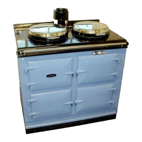
A 100mm (4in) Type B Gas Vent must be used and fastened by screw to the draft hood flue
collar.
U.S.
The gas vent must be connected to a chimney or independently and in accordance with Chapter
26, chimney, Gas Vent and Fireplace Systems of the current issue of Equipment and Volume of
the ASHRAE Handbook. The gas vent proximity to combustible materials must be installed as
recommended in ANSI/NFPA 211 and according to manufacturers instructions. Chimneys and
vents shall terminate above roof level and in accordance with the requirements of the current
issue of ANSI/NFPA 211 (see diagrams) and be at least 1.53m (5ft) above the flue collar of the
draft hood outlet.
Part 7, Venting Equipment, outlined in the current National Gas Code NASI Z223, outlined in the
current guidelines on all these aspects.
Canada:
The gas vent must be connected to a chimney or independently and in accordance with the
CAN/CGA - B149 installation codes.
The air gap between vent and combustible materials must be given for the following types of
vent:
(i) Type B Vent - 25mm (1in) minimum.
(ii) Single wall vent connector - 150mm (6in) minimum.
Listed connectors passing through the combustible walls and partitions must be guarded by a
ventilated metal thimble not less than 200mm (8in) diameter.
Chimneys and vents shall terminate above roof level and in accordance with the requirement of
the current issue of the CAN/CGA - B149 Installation Code (Code W) (see diagrams) and be at
least 1.53m (5ft) above the flue collar of the draft outlet.
1. If suitable lined brick chimney is used it must be swept before connection and not less
than 150mm (6in) internal diameter.
2. The top of the chimney should be fitted with an approved Terminal.
3. The flue route to the chimney should be as direct as possible. Resistance in the form of
directional change should be kept to a minimum. Right angle bends and horizontal runs
should be avoided.
4. The chimney terminal should terminate at the highest possible point, preferably in a freely
exposed position.
Termination at the roofs eaves is unacceptable.
5. The Aga Distributor or Local Gas Company should be advised where any doubt as to the
suitability of the flue.
6. Approved factory made chimneys are acceptable with the appliance and should not be less
than (4in) internal diameter.
7. In the event of an extractor fan being fitted in the vicinity of the range, compensatory
ventilation will be required to satisfy the demands of the fan without influencing
combustion efficiency or chimney flue condition.
VENT CONNECTION
5

