AGA MARVEL 60RDE Manual

Installaon
Operaon
and
Maintenance
Instrucons
Refrigerated Drawer Model
60RDE

1
CONTENTS
Unpacking your refrigerated drawer unit.....
.........
............
Removing the packaging......................
............
...............
Warranty Registraon.....................
.............
....................
Installing your refrigerated drawer unit.....
............
............
Selecng the locaon..........................
.............
..............
Cabinet Clearances..........................................................
Leveling legs......................................
.............
.................
Grounding method..............................
..........
...................
Electrical Requirements........................
...........
................
Installing the an p device...................................... .........
Dimensions Indoor Model 60RDE...............
.........
...............
Recommended Rough in Opening Dimensions
Indoor Model 60RDE
.
.........
..
....
.......................................
Using Your Refrigerated Drawers.........
...............
...............
Starng Your Appliance......................
.............
.................
Set Your Temperature Mode............................................
Set the Desired Temperature..............
..............
................
Load Your Appliance..........................
.............
..................
Interior Light.....................................
.................
...............
Defrost Cycle....................................
...............
..................
Sabbath Mode...............................
...............
....................
Warning Alarms............................
..............
......................
Sentry System™ Quick Reference...........
............
................
Care and Cleaning...................................
..........
.................
E-Z Store Storage System (Oponal)........
.............
..............
Drawer Dividers (Oponal)..............
.......
............
...............
Troubleshoong Guide.........................
...........
...................
Obtaining Service...............................
................
................
Household Product Warranty................
...............
..............
Important Safety Instrucons
Warnings and safety instrucons appearing in this guide are not
meant to cover all possible condions and situaons that may
occur. Common sense, cauon, and care must be exercised when
installing, maintaining, or operang this appliance.
Recognize Safety Symbols,
Words, and Labels.
WARNING-Hazards or unsafe pracces which could result in
personal injury.
CAUTION-Hazards or unsafe pracces which could result in
personal injury or property or product damage.
NOTE
NOTE-Important informaon to make a problem free installa-
on.
2
2
2
3
3
3
3
3
3
4
5
5
6
6
6
6
6
6
6
6
7
8/9
10
11
11
12
13
14
is commied to building a quality product
in an environmentally friendly manner. Our processes are ghtly
controlled and closely monitored. We have achieved cerca-
ons in ISO 9001 for quality assurance and ISO 14001 for environ-
mental management from Lloyd’s Register Quality Assurance.

UNPACKING YOUR REFRIGERATED DRAWERS
2
Remove Packaging
Your refrigerated drawers have been packed for shipment with
all parts that could be damaged by movement securely fastened.
Cut the banding material at the boom of the carton, unfold
the cartoning at the boom and remove the carton from the
appliance. Remove the plasc bag, styrofoam corner posts, and
any tape holding the drawers closed and internal components
in place. The owners manual is shipped inside the drawer in a
plasc bag along with the warranty registraon card.
Important
Keep your carton packaging unl your refrigerated drawers have
been thoroughly inspected and found to be in good condion. If
there is damage, the packaging will be needed as proof of dam-
age in transit. Aerwards please dispose of all items responsibly
in parcular the plasc bags which can be a suocaon hazard.
Note to Customer
This merchandise was carefully packed and thoroughly inspected
before leaving our plant. Responsibility for its safe delivery
was assumed by the retailer upon acceptance of the shipment.
Claims for loss or damage sustained in transit must be made to
the retailer.
DO NOT RETURN DAMAGED MERCHANDISE TO THE MANUFAC-
TURER - FILE THE CLAIM WITH THE RETAILER.
Help Prevent Tragedies
Child entrapment and suocaon are not problems of the past.
Junked or abandoned refrigerators are sll dangerous - even if
they sit out for “just a few days”.
If you are geng rid of your old refrigerator, please follow the
instrucons below to help prevent accidents.
Before you throw away your old refrigerator or freezer:
Take o the doors or remove the drawers.•
Leave the shelves in place so children may not easily climb •
inside.
If the unit was shipped or has been laying on its back for any
period of me allow the refrigerator to sit upright for a period of
at least 24 hours before plugging in. This will assure oil returns
to the compressor. Plugging the refrigerator in immediately may
cause damage to internal parts.
It is important you send in your warranty registraon card imme-
diately aer taking delivery of your refrigerated drawers or you
can register online at www.agamarvel.com.
The following informaon will be required when registering your
unit.
Model Number
Serial Number
Date of Purchase
Dealers name and address
The model number and serial number ca be found on the serial
plate which is located on the boom of the cabinet liner in the
le front corner. Open the boom drawer to full extension to
view it.
Warranty Registraon

INSTALLING YOUR REFRIGERATED DRAWERS
Select Locaon
The proper locaon will ensure peak performance of your ap-
pliance. We recommend a locaon where the unit will be out
of direct sunlight and away from heat sources. To assure your
product performs to specicaons the recommended installaon
locaon temperature range is from 55 to 100°F (13 to 38°C).
Cabinet Clearance
Venlaon is required from the boom front secon of the unit.
Keep this area open and clear of any obstrucons. Adjacent
cabinets and counter top can be installed around the unit as long
as the grille and drawer access remain unobstructed.
3
Figure 2
Do not splash or spray water from a hose on the refrigera-•
tor! Doing so may cause an electrical shock, which may
result in severe injury or death.
This unit should not, under any circumstances, be un-•
grounded.
Grounding Method
This product is factory equipped with a power supply cord that
has a three-pronged, grounded plug. It must be plugged into a
mang grounding type receptacle in accordance with the Na-
onal Electrical Code and applicable local codes and ordinances
(see Figure 2). If the circuit does not have a grounding type re-
ceptacle, it is the responsibility and obligaon of the customer to
exchange the exisng receptacle in accordance with the Naonal
Electrical Code and applicable local codes and ordinances. The
third ground prong should not, under any circumstances, be cut
or removed.
Electrical Connecon
115 volts, 3.3 amps running max. A 15 amp dedicated circuit is
required. A 3 prong grounded receptacle is required.
Leveling Legs
Front Grille, keep
this
area open.
Figure 1
Do not use an extension cord with
this appliance.
Front Grille
Do not obstruct the front grille. The openings within the front
grille provide air to ow into and exit from the refrigerator
condenser. For this reason it is important this area to not be ob-
structed and be kept clean. AGA MARVEL does not recommend
the use of custom made grilles as air ow may be restricted
because of inadequate openings. (See Figure 1).
Leveling Legs
Adjustable legs at the front and rear corners of the unit should
be set so the unit is rmly posioned on the oor and level from
side to side and front to back. Turn leveling legs clockwise to
raise unit, counterclockwise to lower it. (See Figure 1).

INSTALLING THE ANTI-TIP DEVICE
4
A cabinet “an–p” device is mounted to the back of your refrig-
erated drawer unit. If your installaon is a built – in under coun-
ter applicaon with a counter-top directly above the unit this
item can be removed, it does not need to be applied. If your unit
is a freestanding applicaon with no counter-top directly above
the top of the unit, you must apply this feature to prevent the
unit from pping forward when the drawers are pulled out. The
an–p device is installed on the back of the unit. The an–p
device reduces the chance of personal injury as well as property
damage when properly installed between the back of the unit
and the adjacent wall. Please see the following instrucons for
installing the an-p device.
1. Push the unit against the wall so the an-p
bracket is ush to the wall adjacent to the back
panel. Level the unit with the leveling legs provided
in the cabinet boom. (See Leveling Legs on
page 3).
2. Using a pencil and the bracket as a template, trace
the bracket on the wall, making sure 2 of the screw
holes are aligned with a stud in the wall.
3. Pull the unit away from the wall.
4. Remove the screws that connect the upper and
lower secons of the an-p bracket.
5. Place the bracket on the wall and mark and drill
3/16” diameter pilot holes for the provided ¼” lag
screws. Mount the lower secon to the wall with the
¼” lag screws.
6. Move the unit into place aligning the screw holes
between the upper and lower brackets and secure
with the screws removed in step 4.
An - Tip Device
An-Tip device
Figure 3
To Wall
To Refrigerated
Drawer Cabinet
Remove these screws to separate
upper and lower secons of an-p
bracket.
Figure 4 1/4” Lag screws
into wall

RECOMMENDED ROUGH IN OPENING DIMENSIONS, INDOOR MODEL 60RDE
DIMENSIONS INDOOR MODEL 60RDE
23-7/8”
(60.7 cm)
An p Bracket must be
installed for freestanding ap-
plicaons. Can be removed for
built in applicaons.
Front and Rear
Leveling Legs
1-7/8”
(4.8 cm)
24-1/4”
(61.6 cm)
34-1/4” to 34-1/2”
(87 to 87.6 cm)
22”
(55.9 cm)
26-1/32”
(66.1 cm)
46”
(116.8 cm)
47-25/32”
(121.4 cm)
Drawer fully opened
Drawer fully opened
5
Electrical Requirements: 115 volts, 3.3
amps running max. 15 amp dedicated
circuit required. 3 prong grounded
receptacle required.
Power outlet can be located in the back
wall behind unit. Add 1” to depth for
thickness of plug, or recess outlet 1”
into the wall. Power outlet can also be
installed in adjacent cabinetry with a
cutout for roung of power cord. Follow
all local building codes when installing
electrical and unit.
Product weight = 170 lbs. (77.1 kg.)
*Depth dimension may very depending on each
individual installaon.
24”
(61 cm)
34-1/2”
(87.6 cm)
Alternate
outlet locaon
in adjacent
cabinetry.
*24” (61 cm)
standard cabinet depth

Start Your Appliance
Your refrigerated drawers have been ed with a Sentry Sys-
tem™ refrigeraon monitor. It is located at the top front of the
cabinet and can be accessed by opening the top drawer. Your
appliance will start upon inial plug-in. On start the Sentry
System™ monitor will ash amber. This is normal. Press the “ON/
OFF” buon and the appliance resets and the LED turns green.
(Refer to Figure 5 above).
Set Your Temperature Mode
This product can display either Fahrenheit or Celsius. To do so,
press the “°F/C” buon on the display panel to change from one
to the other.
Set the desired temperature
The available temperature range of the unit is from 33° to 47°F
(1° to 8° C). This range allows exibility of temperature prefer-
ences and provides the ideal storing and serving temperatures.
The temperature is inially set in the factory at 37° F (3° C). The
temperature set point can be lowered or raised by rst pushing
the “SET” buon on the display pad. A “SET” icon will be dis-
played in the temperature display. Pressing and releasing either
the “WARMER” or “COLDER” buons located on the display pad
will raise or lower the set temperature by one (1) degree at a
me. As with any refrigeraon product, there will be slight tem-
perature variance at dierent locaons within the cabinet.
Load Your Appliance
Load your appliance with your desired items. Please note that
it may take up to 24 hours for your refrigerator to reach the de-
sired temperature once loaded. This will primarily depend on the
amount of contents loaded into the refrigerator and the amount
of opening and closings of the drawers. Consider this when
inially loading the drawers. Best results will be obtained by rst
allowing the drawers to “pull down” to your set temperature
before loading the drawers.
Interior Light
The upper and lower interior lights make it easy to view your
food and beverages. The light will always come on when either
drawer is opened, except when unit is in Sabbath Mode.
Defrost Cycle
In order to maintain opmal performance, your refrigerator must
periodically enter a defrost cycle to clear frost buildup. During
the defrost cycles, the display will show DEF, and changes to
setpoint and °F/°C seng may not be made.
Sabbath Mode
Your refrigerated drawers are equipped with a Sabbath Mode
feature. By acvang this mode, you will be disabling all dis-
plays, audible alarms and lights. To acvate the Sabbath Mode,
press and hold the “SET” buon while pressing the “°F/C” buon
four (4) mes within seven (7) seconds. To disable the Sabbath
Mode, repeat the process. The Sabbath Mode will deacvate
automacally aer 72 hours.
USING YOUR REFRIGERATOR DRAWERS
6
Figure 5 LED

USING YOUR REFRIGERATED DRAWERS
7
Warning Alarms
The Sentry System™ monitor will let you know if your unit is not
funconing properly for the following reasons. Door ajar, high or
low temperature, and power failure. These alarms are explained
below.
Door Ajar Alarm
If the drawer has been le open for over ve (5) minutes, the
alarm will sound and the LED will ash green. This will stop as
soon as the drawer is closed, or can be reset by pressing the
“ON/OFF” buon.
High and Low Temperature
If your unit reaches temperatures outside normal operang
temperatures for your set point for more than one (1) hour, an
alarm will sound and the LED will ash red. This will warn you
that your contents have seen temperatures that may not be con-
ducive for long-term storage. This alarm can be reset by pressing
the “ON/OFF” buon.
Power Failure
If your unit experiences a power failure, the LED will ash amber
unl the alarm is reset by pressing the “ON/OFF” buon.
Reset Alarms
Press the “ON/OFF” buon for approximately one (1) second.
This will reset all audible and display alarms when the buon is
released.
Enable/Disable Sentry System™ Alarms
Press and hold the “SET” key for ve (5) seconds to enable or dis-
able the Sentry System™alarms. LED will display a steady green
when enabled or a steady amber when disabled.
Quick Reference Guide
The quick reference guide on page 8 and 9 can be removed from
this manual and retained near the appliance for quick access to
the Sentry System™ funcons.
Figure 6 LED

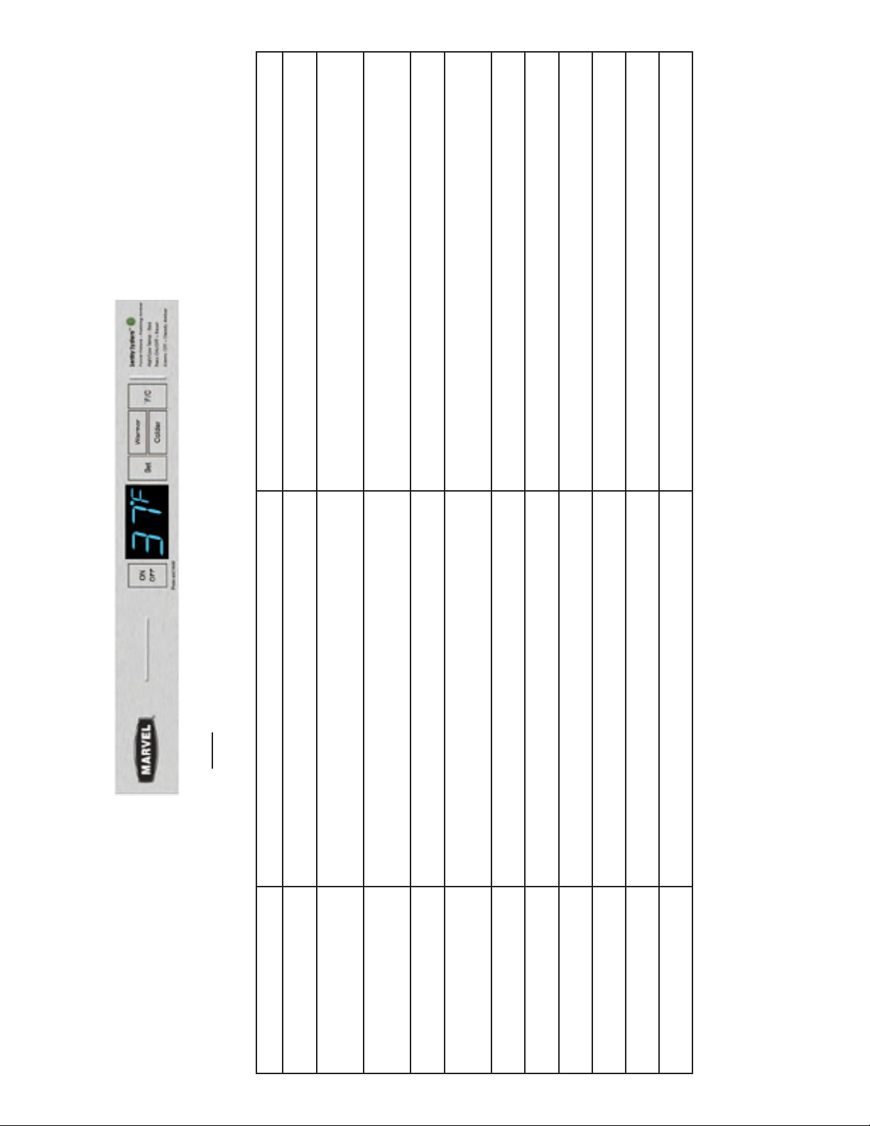
Sentry System™ “Basic” Funcon “Quick” Reference
Note: All keypad presses are conrmed with an audible tone when released.
Funcon Funcon Access Control Conrmaon / Comment
Turn Unit On & O Pressing and holding the “On/O” key for ve seconds will turn the unit “ON” or
“O”.
The display will be blank when the refrigeraon system is o. Lights will sll funcon, but will
me-out in 15 minutes aer each acvaon if drawer is le open, to prevent overheang.
Adjust and View Temperature
set-point
To adjust the temperature set-point, press the “SET” key and current set-point will
be displayed. Use the “WARMER” or “COLDER” keys to adjust set-point tempera-
ture.
“SET” will appear in temperature display when in set-point mode. “SET” mode will automa-
cally me-out in ten (10) seconds if no keypad acvity occurs, or you may exit “SET” mode
by pressing the “SET” key .a second me.
Display “Actual” Temperature
The display represents real me monitoring. Some temperature uctuaon around
the set-point will be noceable as the refrigeraon system cycles on and o to
maintain the desired temperature.
Temperature variaon in “compartment” air, above and below set-point, is a normal eect of
refrigeraon system cycling on and o. Stored items will not experience the full temperature
swing of the compartment air due to the dampening eect of their thermal mass.
Select °F or °C Display Pressing the “°F/°C” key will toggle the display between Fahrenheit and Cengrade
temperature display. i.e. 55°F = 13°C
Sabbath Mode Press and hold the “SET” key while pressing the “°F/°C” key four (4) mes in seven
(7) seconds.
The display will ash “SA” seven (7) mes, then the unit will enter Sabbath Mode. The
display, audible alarms, LED, and lights will be disabled. Sabbath Mode will automacally
me-out in 72 hours., or can be exited by repeang the enabling process.
Sentry System™ alarms No acon required. System monitoring is automacally enabled unless system has
been disabled (see below). Sentry System™ LED displays a steady green when Sentry System™ is enabled.
Drawer Ajar Alarm No acon required if Sentry System™ is enabled. Audible alarm will sound 3 mes every 30 seconds, the LED will ash green. Close drawer to
reset alarm.
High/Low Temp Alarm No acon is required if Sentry System™is enabled. NOTE: This alarm may occur
when changing set-points and/or high usage, this is normal.
Alarm will sound 6-mes every minute and LED will ash red if product temperature excur-
sions occur for a duraon outside acceptable limits.
Power Failure Alarm No acon required if Sentry System™is enabled. NOTE: Alarm will occur upon inial
installaon, since unit was run at the factory to verify quality, this is normal.
LED will ash amber whenever power is interrupted to unit. There is no audible signal. Press
ON/OFF buon to reset alarm.
Reset Alarms Close drawer to reset “DOOR AJAR” alarm. Press the “ON/OFF” key to reset all
other alarms.
Note that although pressing the “ON/OFF” key resets the alarms, the alarm will resume if
the “alarm condion” sll exists.
Enable / Disable Sentry
System™alarms
Press and hold the “SET” key for ve (5) seconds to enable or disable the Sentry
System™ alarms.
LED displays a steady green when alarms are enabled. LED displays a steady amber when
they are disabled.
8

Sentry System™ “Troubleshoong” Funcon “Quick” Reference
Note: All keypad presses are conrmed with an audible tone when released.
Funcon Funcon Access Control Conrmaon / Comment
Show Room Mode
Enable the showroom mode by pressing and holding the “ON/OFF” key while
performing a “Power On Reset” (POR). i.e. disconnect and reconnect the power
supply to the unit. Exit Showroom Mode by iniang a POR only.
Show Room Mode will disable the refrigeraon system and fans while allowing the
internal lights, display, and user interface panel to funcon. Lights will me-out
aer 15 minutes of connuous on-me while in Show Room Mode as a safety
feature. The 15 minute light on me can be reacvated by closing and opening the
door or by pressing the “LIGHT” key.
Error Codes
E1 Compressor fault, (high/low amps)
E2 Condenser fan motor fault, (high/low amps)
E3 Evaporator thermistor “sensor B” fault, (out of range)
E4 Display thermistor “sensor A” fault, (out of range)
Please call a qualied service technician if any of these codes are displayed.
Service Diagnoscs
To enter and exit Service Diagnoscs Mode, press and hold the “WARMER” key
while pressing the “COLDER” key four (4) mes in ve (5) seconds. Service Diag-
noscs Mode will automacally exit aer ve (5) minutes of no keypad entry.
Display Error Code Reference:
The microprocessor in the control connually monitors crical refrigeraon sys-
tem components for proper operaon. If component parameters exceed normal
operaon specicaons, the display will automacally ash the respecve error
code as follows:
Service Diagnoscs Mode enables service technicians to idenfy the rmware and
soware versions, test status of “model specic” system components and sensors,
and change state of components where applicable, (i.e. -compressor “ON/OFF”
etc.). While in Service Diagnoscs Mode, tests are incremented by pressing the
“SET” key and specic component state can be changed to “on” or “o” by pressing
the “WARMER” or “COLDER” keys respecvely. The following component tests are
available:
Available Status Indicators
Test # Component Descripon OK O/
Open
On/
Shorted
0 Temperature Sensor, Upper 0- 00 01
1Temperature Sensor, Lower 1- 10 11
2Compressor n/a 20 21
3Interior / Ice Maker Fan n/a 30 31
4Reverse Gas Solenoid n/a 40 41
5Condenser Fan n/a 50 51
6 Mullion Heater n/a 60 61
7Door A Sense n/a 70 71
8Door B Sense n/a 80 81
9Door C Sense n/a 90 91
NOTE: The Door Sense is located between the Upper Compartment Display and the
“ON/OFF” key and can be tested with any magnet.
Door sense “C” (Test #9) is in the menu but not available on drawer units.
9

10
CARE AND CLEANING OF YOUR REFRIGERATED DRAWERS
Condenser
The machine compartment located beneath the cabinet does
not require frequent cleaning; however, sasfactory perfor-
mance depends on adequate venlaon. Be sure nothing ob-
structs the required air ow openings in front of the cabinet. At
least once or twice a year, brush or vacuum lint and dirt from the
front grille openings. See Figure 1 on page 3.
Cabinet
The painted cabinet can be washed with either a mild soap and
water and thoroughly rinsed with clear water. NEVER use abra-
sive scouring cleaners.
Interior
Wash interior compartment with mild soap and water. Do NOT
use an abrasive cleaner, solvent, polish cleaner or undiluted
detergent.
Care of Unit
Avoid leaning on the drawer fronts, you may bend the 1.
drawer slides or p the unit.
Exercise cauon when sweeping, vacuuming or mopping 2.
near the front of the unit. Damage to the grille can occur.
Periodically clean the interior of the unit as needed.3.
Periodically check and/or clean the front grille as needed.4.

AVAILABLE OPTIONS FOR YOUR DRAWER REFRIGERATOR
E-Z Stor Storage System
Removable stainless steel bins with clear plasc lids can be
moved to prep, cook, or serving areas as desired. Available for
60RDE upper and lower drawers.
P/N 42245441 for 60 upper or lower drawers.
Drawer Dividers
Fully adjustable stainless steel drawer dividers allow for opmum
storage and organizaon of storage space.
P/N 42245444 for 60RDE upper drawer.
P/N 42245445 for 60RDE lower drawer.
For further informaon on available opons visit the AGA
MARVEL web-site at www.agamarvel.com or contact your AGA
MARVEL dealer.
Plasc lids
Stainless steel bins
Stainless steel divider ts
on top of drawer sides.
Figure 7
E-Z-Store Storage System
Stainless steel rods
Adjustment knob
Figure 8
Drawer Dividers
When installing these opons in the drawers the standard
drawer divider will have to be removed.
NOTE
11

TROUBLESHOOTING YOUR REFRIGERATED DRAWERS
Problem Possible Cause Remedy
Unit not cold enough. Control set too warm.•
Airow to front grille blocked.•
Excessive usage or prolonged drawer •
openings.
Drawer gasket not sealing properly.•
Adjust temperature colder. (See “Set •
the desired temperature” on page 6).
Allow 24 hours for temperature to
stabilize.
Airow must not be obstructed to •
front grille. See “clearances” on page
3.
Allow temperature to stabilize for at •
least 24 hours.
Adjust or replace drawer gasket.•
Unit too cold. Control set too cold.• Adjust temperature warmer. (See •
page 6, “set the desired tempera-
ture”). Allow 24 hours for tempera-
ture to stabilize.
No interior light in drawer compartments. Failed LED interior light assembly.• Contact a qualied AGA MARVEL •
service technician.
Light will not go out when drawer is
closed.
Drawer not acvang light switch.• Unit not level, level unit, (See page 3, •
“leveling legs”)
Noise or Vibraon. Unit not level.• Level unit, see “Leveling Legs” on •
page 3.
Unit will not run. Unit turned o.•
Power cord not plugged in.•
No power at outlet.•
Turn unit on. See “Start your Appli-•
ance” on page 6.
Plug in power cord.•
Check house circuit.•
Before You Call for Service
If the unit appears to be malfunconing, read through this
manual rst. If the problem persists, check the troubleshoong
guide below. Locate the problem in the guide and refer to the
cause and its remedy before calling for service. The problem may
be something very simple that can be solved without a service
call. Some remedies listed in the Troubleshoong Guide are very
complex. Consulng or contracng a qualied service technician
may be necessary.
Electrocuon Hazard - Never aempt to repair or perform main-
tenance on the unit unl the main electrical power has been
disconnected.
12

OBTAINING SERVICE
If Service is Required:
If the product is within the rst year warranty period please •
call AGA MARVEL Customer Service at 800.223.3900 for
direcons on how to obtain warranty coverage in your area.
If the product is outside the rst year warranty period, AGA •
MARVEL Customer Service can provide recommendaons of
service centers in your area. A lisng of authorized service
centers is also available at www.agamarvel.com under the
service and support secon.
In all correspondence regarding service, be sure to give the •
model number, serial number, and proof of purchase.
Try to have informaon or descripon of nature of the prob-•
lem, how long the unit has been running, the room temper-
ature, and any addional informaon that may be helpful in
quickly solving the problem.
Fill in pernent informaon below regarding your product •
for future reference.
For Your Records
Date of Purchase
Dealer’s name
Dealer’s Address
Dealer’s City
Dealer’s State
Dealer’s Zip Code
Appliance Serial Number
Appliance Model Number
Date Warranty Card Sent
(Must be within 10 days of
purchase).
13

14
any consequenal or incidental damages or expenses resulng
from breach of these or any other warranes, whether express
or implied.
Some states do not allow the exclusion or limitaon of conse-
quenal damages or a limitaon on how long an implied war-
ranty lasts, so the above exclusion or limitaon may not apply
to you. This warranty gives you specic legal rights and you may
have other rights that may vary from state to state.
No person, rm, or corporaon is authorized to make any other
warranty or assume any other obligaon for AGA MARVEL.
These warranes apply only to products used in any of the y
states of the United States and the District of Columbia.
To obtain performance of this warranty, report any defects to:
P.O. Box 400
1260 E. VanDeinse St.
Greenville MI 48838
Phone: 800.223.3900
Enre Product
Limited One Year Parts and Labor Warranty
AGA MARVEL warrants that it will supply all necessary parts and
labor to repair or replace in the end user’s home or oce, any
component which proves to be defecve in material or work-
manship, subject to the condion and exclusions stated below,
for a period of one year from the date of purchase by the end
user.
Addional Second Through Fih Year
Limited Parts Only Warranty
During the four years following expiraon of the one year limited
warranty, AGA MARVEL will supply replacement parts for the
hermecally sealed refrigeraon system which consists of the
compressor, condenser, drier, accumulator, bypass valve, con-
necng tubing and the evaporator that are proven to be defec-
ve due to workmanship or materials subject to the condions
and exclusions below.
The above warranes do not cover:
Shipping costs of replacement parts or returned defecve •
parts.
Customer educaon or instrucons on how to use the appli-•
ance.
Any content loss due to product failure.•
Removal or installaon of product.•
Nor do the above warranes cover failure of this product or its
components due to:
Transportaon or subsequent damages.•
Commercial use or use other than normal household or •
small oce.
Improper installaon, misuse, abuse, accident or alteraon, •
use of wiring not conforming to electrical codes, low or high
voltages, failure to provide necessary maintenance, or other
unreasonable use.
Parts or Service not Supplied or Designated by AGA •
MARVEL.
The above warranes also do not apply if:
The original bill of sale, deliver date, or serial number can-•
not be veried.
Defecve parts are not returned for inspecon if so request-•
ed by AGA MARVEL.
The refrigeraon equipment is not in the possession of the •
original end use purchaser.
The warranes set forth herein are the only warranes extended
by AGA MARVEL. Any implied warranes, including the implied
warranty of merchantability, are limited to the duraon of these
express warranes. In no event shall AGA MARVEL be liable for
HOUSEHOLD PRODUCT WARRANTY

All specicaons and product designs subject to change without noce. Such revisions do not entle the
buyer to corresponding changes, improvements, addions, replacements or compensaon for previously
purchased products.
www.agamarvel.com
P.O. Box 400
1260 E. VanDeinse St.
Greenville MI 48838
800.223.3900
41011913-EN Rev A
2/2/10
Table of contents
Other AGA Refrigerator manuals

AGA
AGA Marvel AMPROFD23D Technical manual

AGA
AGA Marvel AMLFDR23D User manual

AGA
AGA APRO36FD User manual

AGA
AGA R2 User guide

AGA
AGA Legasy AFHR-36 User manual

AGA
AGA RSXSDL21 Deluxe Manual

AGA
AGA ASXS21 Manual

AGA
AGA Premium Series User manual

AGA
AGA 60RDA 115V Installation instructions

AGA
AGA ML24RF Manual