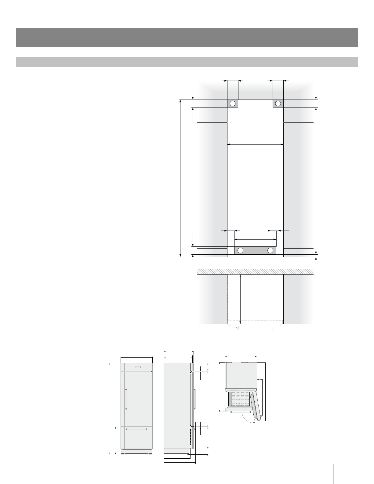
Transport to installation site and unpacking
Since this is a large and heavy appliance, before transporting
the appliance, check the access to the location where it will be
installed (door size, manoeuvring space in stairwells, etc.).
It may be convenient to remove a part of the packaging before
transporting to the installation site, taking maximum care to protect
the appliance from scratches and damages.
The appliance is secured to the base of the packaging (pallet) by
four bolts which can be removed using a 17 mm wrench.
It is recommended to use a manual transporting device to move the
appliance to the installation site, and only at this point to remove the
base of the packaging.
The appliance should always be transported in an erect position. If this
is not possible, transport it laying on its rear side, avoiding at all costs
laying it on its front side.
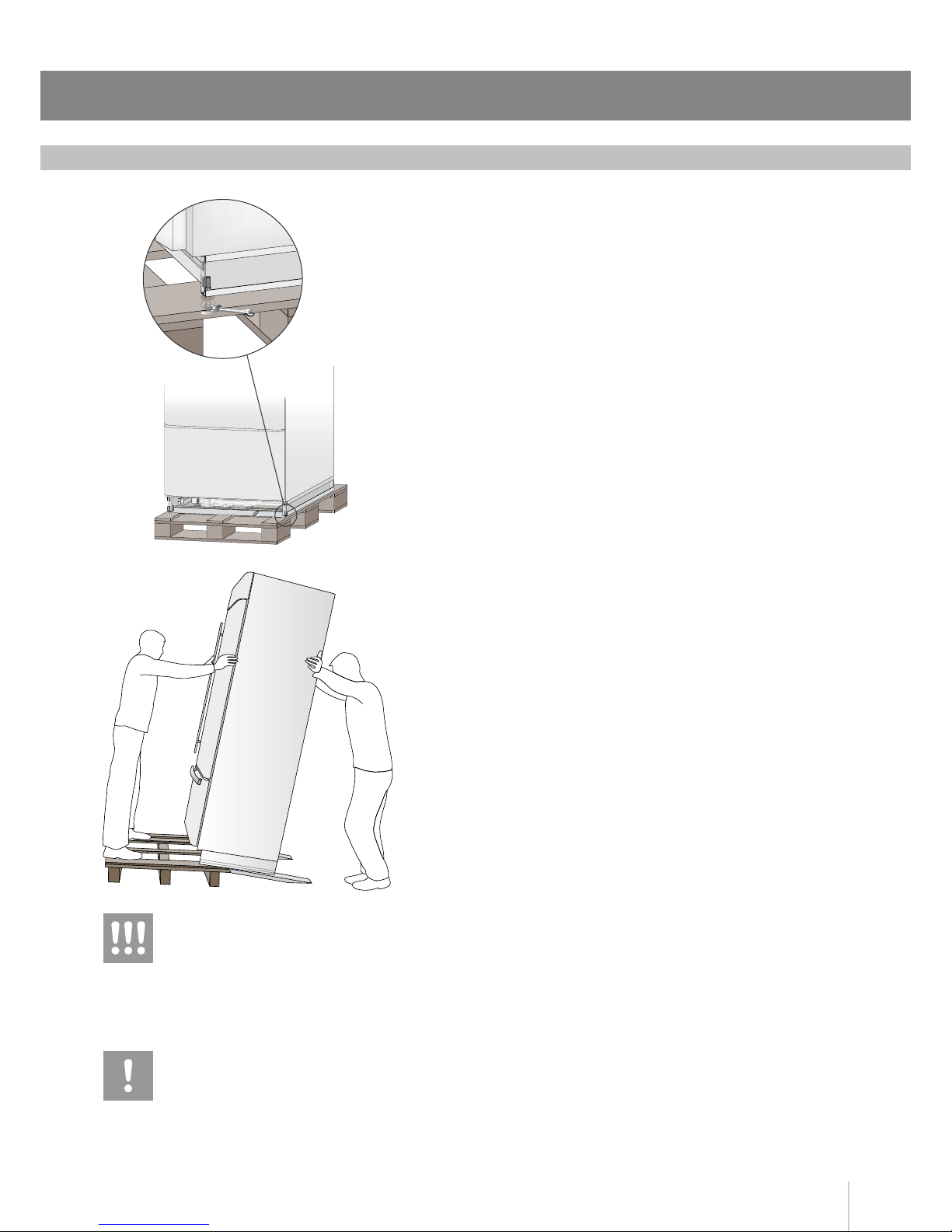
Once the installation site has been reached, it is necessary to remove
the four anchor bolts that hold the appliance to the pallet (use a 17 mm
wrench). Once at the installation site, the appliance, which is equipped
with four wheels, can be taken off the pallet (two slide guides are
provided for this purpose, see illustration) and positioned in the correct
location.
Be extremely careful during this operation, and do not lean the
appliance any more than necessary when placing it on the slide guides
(max 70°< ) to avoid grave harm to persons and property.
Be very careful to avoid any damage to oors. Especially delicate
oors should be protected with plywood, hard cardboard or similar
material panels.
The appliance is very heavy.
Take maximum care during handling
to avoid injury.
The appliance should always be transported
in an erect position.
Avoid at all costs leaning it on its front side.