AGD 306 User manual

✓
PRODUCT MANUAL
© AGD Systems Limited 2019 Doc. Ref 306 PM ISS1
AGD 306
TRAFFIC CONTROL RADAR
AGD 306
TRAFFIC CONTROL RADAR
AGD 306
TRAFFIC CONTROL RADAR
AGD 306
TRAFFIC CONTROL RADAR

2
INTRODUCTION
Product & technology 3
Key features 3
Typical applications 4
Product overview image 5
Product variants 5
Product overview 5
INSTALLATION AND COMMISSIONING
Physical installation 6
Electrical installation 7-8
Connecting 9
Set-up device using AGD Touch-setup 10-14
TECHNICAL RESOURCE
Transmit channel - typical scenarios 15-16
TROUBLESHOOTING
Physical installation 17
Connecting / Commissioning 18
RADAR CHARACTERISTICS
Radar Characteristics 19
Frequency Variants 20
306 Field Pattern 21
TECHNICAL SPECIFICATIONS
Product specification 22
CERTIFICATES 23
END OF LIFE – DISPOSAL INSTRUCTIONS (EOL) 24
IMPORTANT SAFETY INFORMATION
Safety precautions 25
Low power non-ionising radio transmission and safety 26
DISCLAIMER
Warranty 28
safer, greener, more eicient
AGD 306
TRAFFIC CONTROL RADAR
AGD 306
TRAFFIC CONTROL RADAR
AGD 306
TRAFFIC CONTROL RADAR
AGD 306
TRAFFIC CONTROL RADAR
Table of Contents

3
AGD 306
TRAFFIC CONTROL RADAR
AGD 306
TRAFFIC CONTROL RADAR
AGD 306
TRAFFIC CONTROL RADAR
AGD 306
TRAFFIC CONTROL RADAR
PRODUCT & TECHNOLOGY
KEY FEATURES
• Easy setting configuration means one product for many applications
• Range configurable up to 120m
• Accurate detection zone for improved host system efficiency
• Performance is super tolerant to weather conditions and other sources of interference
• WiFi AGD Touch-setup - speeds installation & reduces risk
• Huge 50% reduction in power consumption on previous AGD206 product
• Architecture based on 32 bit ARM® Cortex® processing core
The AGD306 is a smart FMCW radar which is
designed to make vehicle movements at Traic
Control Installations more eicient. The design is
also robust, cost-eective and highly configurable
which also makes it suitable for multiple
Intelligent Transport Systems (ITS) management
applications.
The radar operation is ‘trickle-down’ technology
from the proven and approved AGD range of speed
enforcement products giving it significant pedigree at
this level of product.
Configuration of the radar’s settings is via the unique
WiFi AGD Touch-Setup which allows users to set and
monitor the radars performance wirelessly from
a smart-phone or tablet without any proprietary
soware or app.
Introduction

4
AGD 306
TRAFFIC CONTROL RADAR
AGD 306
TRAFFIC CONTROL RADAR
AGD 306
TRAFFIC CONTROL RADAR
AGD 306
TRAFFIC CONTROL RADAR
TYPICAL APPLICATIONS
Intersection control
Shuttle operation
Introduction

5
AGD 306
TRAFFIC CONTROL RADAR
AGD 306
TRAFFIC CONTROL RADAR
AGD 306
TRAFFIC CONTROL RADAR
AGD 306
TRAFFIC CONTROL RADAR
PRODUCT OVERVIEW IMAGE
Front (power on)
detect LED
Pan and tilt
mounting foot Power only (230V version)
power and opto output
(12/24V version)
Relay output
(230V only)
Introduction
PRODUCT VARIANTS
PRODUCT OVERVIEW
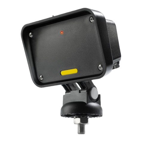
The AGD306 is an above ground dynamic radar detector. This compact unit, featuring a custom planar antenna
has been specifically designed to detect a variety of targets at greater distances, whilst reducing power
consumption by 50% over its predecessor. Improved tolerance to external sources of interference further
improves host system eiciency.
The detector has a configurable, single zone of detection, covering a range of 5 to 120m along the carriageway.
An output is generated by the detector as the target travels above the low speed threshold within the specified
area of detection.
The detector utilises AGD’s WiFi Touch-setup. This 3 step process allows simple and easy configuration via a
laptop, tablet or mobile device, without the need for any additional soware or applications. Parameters that
can be altered include detection direction (advancing, receding or bi-directional), low speed threshold (4 or 8
kph), maximum range (30-120m) and transmission channels (1-2), to help prevent interference between units.
New settings are implemented upon saving.
Product No. Description
306-500-021 Perm signal radar / 12/24V ac/dc / 24GHz / Dual lane / Single opto output / 1m lead + 1.5m mating lead
306-501-021 Perm signal radar / 12/24V ac/dc / 24GHz / Dual lane / Single opto output / 1m lead + 4m mating lead
306-502-021 Perm signal radar / 12/24V ac/dc / 24GHz / Dual lane / Single opto output / 5m flying lead
306-300-021 Perm signal radar / 230Vac / 24GHz / Dual lane / Single relay output / 5m flying leads
Rear (power on)
detect LED

6
AGD 306
TRAFFIC CONTROL RADAR
AGD 306
TRAFFIC CONTROL RADAR
AGD 306
TRAFFIC CONTROL RADAR
AGD 306
TRAFFIC CONTROL RADAR
STEP 3 - VERIFICATION AND ADJUSTMENT - Confirm that the radar is correctly aligned by ensuring that targets
are reliably detected within the specified detection zone. Adjust if necessary and retest. Once aligned correctly,
ensure that the mounting nut is fully tightened and that the detector is secure.
Installation and Commissioning
PHYSICAL INSTALLATION
STEP 1 - MOUNTING HEIGHT
The AGD306 radar has been
designed to operate at a
mounting height of between
2m-5m, with an unobstructed
view of the detection zone.
Height extension bracket
BR-129 should be used
where required.
STEP 2 - DETECTOR ALIGNMENT - The AGD306
should be mounted using the supplied hardware.
Direct the radar to point at the center of the furthest
point of detection. For short range applications the
detector should be angled down as shown in the
diagram below. Lightly tighten the mounting nut to
prevent any movement.
5m max
2m min
30m 120m
Radar angled for
shorter range
applications
Vertical mounting
for longer range
applications
User Configurable Detection Range
Detector
mounted
at 3m

7
AGD 306
TRAFFIC CONTROL RADAR
AGD 306
TRAFFIC CONTROL RADAR
AGD 306
TRAFFIC CONTROL RADAR
AGD 306
TRAFFIC CONTROL RADAR
ELECTRICAL INSTALLATION
12/24V ac/dc – Multi-pin Connector or 5m Flying Lead
The AGD306 is powered by a 12/24V ac/dc supply.
Power is supplied to the detector using the multi-pin
mating connector.
The AGD306 is provided with a Buccaneer Series
PX0728/S 9 Pin connector to enable direct
connection to the traic control system.
The pinouts of the connector and detector
function are shown below:
Opto-coupler ratings
• Max current 100mA
• Max voltage 100V
• Max on-state impedance 25 Ohms
Pi n 1
Pi
n 2
Pi n 3
Pi n 4
Pi n 5
Pi n 6
Pi n 1
Pi n 2
Pi n 3
Pi n 5
Pi n 4
Pi n 6
Pin view of bulkhead
connector
Pin view of multi-pin
connector
Installation and Commissioning
The voltage tolerances of supply are as follows:
• 10-30Vdc
• 24Vac ± 20% ac
Single Cable 12Vdc/24V ac/dc Supply Wiring (1m lead with multi-pin connector)
Pin No. Wire Colour Function Power Off Power On-No Detect Power On-Detect
1Red 12/24Vdc (+) or 24Vac - - -
2 Black 0V - - -
3 Green Not Connected - - -
4 White Common - - -
5 Yellow Opto N/O N/C N/O
6 Blue Opto N/C N/O N/C
7, 8, 9 Not Connected
Single Cable 12Vdc/24V ac/dc Supply Wiring (5m flying lead)
Wire Colour Function Power Off Power On-No Detect Power On-Detect
Red 12/24Vdc (+) or 24Vac - - -
Black 0V - - -
Green Earth / Ground - - -
White Common - - -
Yellow Opto N/O N/C N/O
Blue Opto N/C N/O N/C

8
AGD 306
TRAFFIC CONTROL RADAR
AGD 306
TRAFFIC CONTROL RADAR
AGD 306
TRAFFIC CONTROL RADAR
AGD 306
TRAFFIC CONTROL RADAR
ELECTRICAL INSTALLATION
230Vac - 5m Flying Leads
The AGD306 is powered by 230Vac and it is essential that the detector is connected to the correct power supply.
Consideration must be given to the multiple grounding of supplies and to its eect on the whole system. The
detector is supplied with two 5m flying leads. One is the power supply for the detector and the other is the signal
output and the correct cables should be identified before connection.
The switched outputs on the 230V variants are relays. It should be noted that the relays are rated at Max 230Vac and
500mA but also must have a minimum whetting load of 12Vdc 100mA. In addition the relay outputs are protected by
protection device which limits current to 500mA and has a serial impedance of approximately 15 Ohms.
APPLYING POWER
• Make sure the power supply is the correct
voltage, which can be found on the label on
the unit.
• Connect the unit to the supply.
• Once powered, the front and rear LEDs should
flash five times whilst the radar performs its
self check routines.
Upon power up, owing to the nature of the equipment’s power supply, an initial current of up to 200mA can be
drawn and the supply should be fused as follows:
230V models: This product must be protected by a 3A circuit breaker.
12/24V Models: This product must be protected by a 1A circuit breaker or in-line fuse.
Typical Power Consumption
• 12Vdc - 70mA (195mA peak)
• 24Vdc - 35mA (85mA peak)
• 24Vac - 56mA (95mA peak)
• 230Vac - 9.6mA (20mA peak)
The installation of this equipment MUST conform to the latest edition of the IEE Wiring Regulations (BS7671).
Installation and Commissioning
CONNECTIONS FOR 230Vac VERSION
Twin Cable 230Vac Supply Wiring (5m flying leads)
Cable Wire Colour Function Power O Power On - No Detect Power On –Detect
Power Brown 230Vac Live - - -
Blue 230Vac Neutral - - -
Signal Red Relay Common - - -
Blue Relay Contact N/C N/O N/C
Green Relay Contact N/O N/C N/O

9
AGD 306
TRAFFIC CONTROL RADAR
AGD 306
TRAFFIC CONTROL RADAR
AGD 306
TRAFFIC CONTROL RADAR
AGD 306
TRAFFIC CONTROL RADAR
CONNECTING
AGD306 is configured using AGD WiFi Touch-setup.
This is a simple, 3 step process, allowing the end user to
connect and configure the unit via browser on their laptop,
tablet or mobile device.
This step-through process describes the actions required to
connect to the radar.
Connecting Wifi
Upon powering up, wait for the LED on the rear of the unit
to flash 5 times, this signifies that the firmware has correctly
started. Search for the unit and identify the unit by its serial
number:
306:XXXXXX-XXXX (the ‘X’ denotes the S/N)
Click ‘connect’ and input the default password:
AGD306:XXXXXX-XXXX (the ‘X’ denotes the S/N)
*please note that this is case sensitive and contains special
characters*
The LED on the rear of the radar should now be
illuminated blue to show that WiFi is successfully connected.
Your device should also show as connected on it’s WiFi
network tab.
Connecting Device
Complete Wifi connection step as above.
Launch a browser on your smartphone, tablet or laptop
(Modern versions of: Internet Explorer, Google Chrome and
Safari are all supported - 2018 onwards).
In the address bar of your browser, enter the ‘IP Address’:
http://192.168.4.1
You will be presented with your initial AGD Touch-setup page.
Installation and Commissioning

10
AGD 306
TRAFFIC CONTROL RADAR
AGD 306
TRAFFIC CONTROL RADAR
AGD 306
TRAFFIC CONTROL RADAR
AGD 306
TRAFFIC CONTROL RADAR
SET-UP DEVICE USING AGD TOUCH-SETUP
Homepage
Homepage displays real time target tracking information. Valid target tracks appear as red dots along the centre
line. This page can be used in conjunction with LED’s on radar unit to confirm reliable target detections within
the required detection zone.
Menu button (top le) gives access to radar settings.
Installation and Commissioning
Menu
Radar Unit Distance (m) Target Tracks
(shown as ‘red dots’)
Clear Button (resets target tracking info)

11
AGD 306
TRAFFIC CONTROL RADAR
AGD 306
TRAFFIC CONTROL RADAR
AGD 306
TRAFFIC CONTROL RADAR
AGD 306
TRAFFIC CONTROL RADAR
SET-UP DEVICE USING AGD TOUCH-SETUP
Settings
Product Information – This provides the user with AGD306 version information and the
ability to populate a free text box. This can be used for identification numbers, or any
other information that may be required (max 62 characters).
If changes are made to ANY settings, this is represented
by an exclamation mark at the end of the box.
Clicking 'R' queries current saved value.
Changes must be saved using the 'SET' button before progressing, otherwise any changes made will be lost.
Installation and Commissioning
Click on the menu
Select ‘Settings’

12
AGD 306
TRAFFIC CONTROL RADAR
AGD 306
TRAFFIC CONTROL RADAR
AGD 306
TRAFFIC CONTROL RADAR
AGD 306
TRAFFIC CONTROL RADAR
SET-UP DEVICE USING AGD TOUCH-SETUP
WiFi Settings
SSID – Allows the user to amend AGD306 WiFi SSID. Format of SSID as standard is as follows:
306:XXXXXX-XXXX (where ‘X’ denotes the serial number of the unit). Characters aer this can be amended
to allow for easy unit identification whilst on-site.
Password – allows user to change WiFi password from default. Default password is as follows:
AGD306:XXXXXX-XXXX (where ‘X’ denotes the serial number of the unit). *Please note – password is case
sensitive and includes special characters*
WiFi Deep Sleep – This setting (when enabled) will disable the WiFi connection aer 24 hours of initial power
up. If a WiFi connection is required aer this period, then the unit will need to be power cycled prior to any
connection attempts. Default setting is ‘enabled’.
Installation and Commissioning
WiFi Deep Sleep
SSID Password

13
AGD 306
TRAFFIC CONTROL RADAR
AGD 306
TRAFFIC CONTROL RADAR
AGD 306
TRAFFIC CONTROL RADAR
AGD 306
TRAFFIC CONTROL RADAR
SET-UP DEVICE USING AGD TOUCH-SETUP
Detector Configuration
Transmit Channel – The AGD306 has 2 channels available (3-4 currently reserved for FCC compliant units). The
default channel alternates based on the serial number of the unit. Odd numbered units are defaulted to channel
1 and even numbered units defaulted to channel 2. Under certain circumstances (such as two units facing each
other in a shuttle working scenario), one unit may require changing to prevent interference between units.
*Check technical resource section for co-locating other AGD radars.
Maximum Range – This sets the maximum distance at which AGD306 reports valid targets. Range is user
selectable 30m-120m (default 60m) in 10m increments.
Low Speed Threshold – This is the speed at which valid targets are reported (default 8kph, 4kph option
available). Any target travelling below the chosen threshold is ignored.
Hold Time – The amount of time the radar maintains it’s detect state, aer a valid target has exited the detection
zone. Default = 800ms, with 500ms or 2000ms options available.
Installation and Commissioning
Low Speed ThresholdHold TIme
Transmit Channel Maximum Range

14
AGD 306
TRAFFIC CONTROL RADAR
AGD 306
TRAFFIC CONTROL RADAR
AGD 306
TRAFFIC CONTROL RADAR
AGD 306
TRAFFIC CONTROL RADAR
SET-UP DEVICE USING AGD TOUCH-SETUP
Detector Configuration (cont)
Direction – Select the direction of traic that requires detection. Select from advance, recede or bi-directional.
Fault Monitor Timeout – When no valid targets are detected within a set period, the radar will assume a fault
condition and default to a permanent detect state. At default (0 seconds) fault monitor timeout is disabled.
Front/Rear LED – Individual control over front and rear LED’s. Option to switch on, o or timeout. If timeout is
selected, LED’s will automatically switch o aer 10 mins of initial power up.
Installation and Commissioning
Front/Rear LED Fault Monitor Timeout
Direction

15
AGD 306
TRAFFIC CONTROL RADAR
AGD 306
TRAFFIC CONTROL RADAR
AGD 306
TRAFFIC CONTROL RADAR
AGD 306
TRAFFIC CONTROL RADAR
TRANSMIT CHANNELS - TYPICAL SCENARIOS
Co-Location of AGD Detectors
Installing two or more AGD detectors e.g 306, 326 or 316, 326 on the same traic signal pole can result in
crosstalk and a degradation in performance if they are on the same frequency.
Please be mindful of additional AGD products located on the same pole or in the vicinity of any new installation.
Example 1: Various On-crossing and MVD/Stop Line Detection
Suggested Settings
* Please contact AGD technical support if attempting to co-locate AGD306 and AGD318.
technical.support@agd-systems.com
Tel: +44 (0) 1452 557404
6
4
21
5
3
Technical Resource
No. AGD Product Channel
1 AGD326 1
2 AGD316 n/a
3
AGD306 2
AGD318 1*
4 AGD326 2
5 AGD316 n/a
6
AGD306 2
AGD318 1/2*

16
AGD 306
TRAFFIC CONTROL RADAR
AGD 306
TRAFFIC CONTROL RADAR
AGD 306
TRAFFIC CONTROL RADAR
AGD 306
TRAFFIC CONTROL RADAR
TRANSMIT CHANNEL - TYPICAL SCENARIOS
Table 1: AGD 24GHz Radar Channels
Technical Resource
24.200G, 13M
24.094G, 1M
24.100G, 9M
24.05 24.06 24.07 24.08 24.09 24.1 24.11 24.12 24.13 24.14 24.15 24.16 24.17 24.18 24.19 24.2 24.21 24.22 24.23 24.24 24.25
302
308
306:CH1
306:CH2
326:CH1
326:CH2
326:CH3
326:CH4
316
317
318 Europe:CH1
318 Europe:CH2
318 USA:CH1
318 USA:CH2
331
335
340
342
343-500:CH3
343-500:CH4
343-501:CH2
350-100:CH1
350-100:CH2
350-100:CH3
350-100:CH4
350-101:CH1/CH3
350-101:CH2/CH4
350-102:CH1/CH3
350-102:CH2/CH4
Frequency (GHz)
AGD 24 GHz Radar Channels
Ramp up Ramp down

17
AGD 306
TRAFFIC CONTROL RADAR
AGD 306
TRAFFIC CONTROL RADAR
AGD 306
TRAFFIC CONTROL RADAR
AGD 306
TRAFFIC CONTROL RADAR
PHYSICAL INSTALLATION
What height should the AGD306 be mounted at?
The AGD306 has a recommended mounting height of between 2-5m (from ground level).
Is there a recommended angle that the AGD306 should be set to?
The AGD306 should be carefully aligned for optimum performance and set-up is best achieved under light
traic conditions.
The detector should be panned to point at the centre of the carriageway at the furthest point at which
detection is required. For a dual carriageway approach the detector should be aligned with the road
markings separating the two lanes. The LED on the detector should be observed during alignment to ensure
the onset of detection occurs at the correct point.
Will AGD306 operate correctly with obstructions?
All radar units are designed to operate with a clear ‘line of sight’. Any obstructions may result in loss of
performance or false detections. The BR-129 height extension bracket should be implemented where
required to avoid potential obstructions from traic light heads.
Troubleshooting

18
AGD 306
TRAFFIC CONTROL RADAR
AGD 306
TRAFFIC CONTROL RADAR
AGD 306
TRAFFIC CONTROL RADAR
AGD 306
TRAFFIC CONTROL RADAR
CONNECTING / COMMISSIONING
How many lanes of traic can the AGD306 detect vehicles in?
The AGD306 can detect targets in up to 2 lanes of bi-directional traic. It is not able to discriminate which
lane a target is traveling in.
What is the maximum range of the AGD306?
AGD306 is configurable to allow detection up to 120m. These functions are available via the AGD
Touch-setup ‘Settings’ page.
Can the AGD306 detect vehicles in both directions?
Yes, the AGD306 can be configured to detect either bi-directional, advancing or receding only traic.
For example; this function is regularly deployed on traic signals where the control of two-way traic across
a single lane, such as ‘shuttle working bridges’ is required.
What speeds can the AGD306 detect vehicles at?
The AGD306 has a selectable low speed threshold of either 8 kph (default) or 4 kph. A detection output will
only be activated if the target is traveling above the selected limit.
If two AGD306’s are facing each other (i.e. shuttle working on a bridge) can their radar signals interfere
with the opposing unit?
Yes. Any radar unit has the potential to interfere with another unit operating within the same band
(frequency). To overcome this, the AGD306 has the option of 2 user selectable channels
(via AGD Touch-setup) to minimize any potential interference between units.
Can the AGD306 detect bicycles?
Yes, the AGD306 will detect bicycles travelling above the low speed threshold. However, as a bicycle is a
smaller target than a motor vehicle, detection range may be reduced.
Why can’t a simple hand-wave test be carried out on the AGD306, the same as could be done on previous models?
The 306 employs a planar antenna and detection and tracking algorithm soware that is optimised only for
the profile of moving vehicles. Waving a hand in front of the 306 does not produce a suitable profile which
the unit would recognise as a valid target and will be ignored. This is very good for filtering out unwanted
targets such as moving tree branches close to the detector.
Troubleshooting

19
AGD 306
TRAFFIC CONTROL RADAR
AGD 306
TRAFFIC CONTROL RADAR
AGD 306
TRAFFIC CONTROL RADAR
AGD 306
TRAFFIC CONTROL RADAR
RADAR CHARACTERISTICS
The radar has been designed to have a specific set of functional characteristics which make it suitable for traic
control applications.
Radar Antenna
The antenna is a planar patch array with the following performance;
Parameter Specified Notes
Horizontal Beam-width 33° -3dB (HPBW)
Vertical Beam-width 33° -3dB (HPBW)
Side-lobe suppression >20dB
E-Field Vertical Plane polarised
Operating Frequency Band and Power
The AGD306 radar utilizes a temperature compensated transceiver design. The hardware has been designed to
operate in the ‘K band’ range of frequencies at 24.215GHz.
Parameter Specified Notes
Centre Frequency 24.215GHz*
Power <100mW eirp
Field Strength Typically 750m V/m At 3m
ITU Code 26M0FXN
*Proposed channels for FCC variant, 24.125GHz
WiFi Frequency and Power
• Frequency range (MHz): 2412-2472
• Highest EIRP power in the range (dBm): 18.52
Radar Characteristics

20
AGD 306
TRAFFIC CONTROL RADAR
AGD 306
TRAFFIC CONTROL RADAR
AGD 306
TRAFFIC CONTROL RADAR
AGD 306
TRAFFIC CONTROL RADAR
FREQUENCY MODULATION
The radar is an FMCW radar where the Frequency Modulation (FM) characteristics give the radar a transmit
bandwidth of 26MHz. The FM is such that it is symmetric about the centre frequency of the band it is
operating in.
The change in transmit ‘bandwidth’ with temperature is measured to be typically 30KHz/˚C. The stability of the
bandwidth over time is anticipated being better than 3% in the first year and lower for each subsequent year.
Technical Specifications
FREQUENCY VARIANTS
Several versions of this product are available at frequency options which are for use in dierent geographic
regions related to the radio requirements of that specific jurisdiction as follows;
Frequency Variant EU Country of Use Other Countries Notes
24GHz IE, UK, BE, DK, ES, FI, EL, IT, NL, PT, SE, NO,
For other EU countries please contact AGD.
These products may not be used in the following geographic regions;
Restriction Type EU Country Other Countries
Relevant 24GHz Band not allocated USA, CAN
Licence Required for Use
Frequency Allocated but EIRP too high
It is important to note that this table is updated from time to time. Please contact AGD for latest information if
your intended country of use is not currently represented.
(Note: Countries are listed by their ISO 3166 2 letter code)
Table of contents
Other AGD Radar manuals
Popular Radar manuals by other brands

Endress+Hauser
Endress+Hauser Micropilot FMR63B technical information

Endress+Hauser
Endress+Hauser Hart Micropilot FMR60B operating instructions

Endress+Hauser
Endress+Hauser Micropilot FMR62B Brief operating instructions

Raytheon
Raytheon R40 user guide

Decatur Electronics
Decatur Electronics SVR DUAL user manual

smartmicro
smartmicro UMRR-0C Type 42 user manual

Microbrain Intelligent Technology
Microbrain Intelligent Technology ITS-AX1 user manual

AirNav
AirNav RadarBox manual

Bosch
Bosch FR5CPCCF manual

Carmanah
Carmanah G Series Cabinet Door Replacement Guide

Magnetrol
Magnetrol Pulsar Foundation fieldbus R96 operating manual

RHYTHM
RHYTHM Hawkeye troubleshooting guide